STONECOLD POWER AMPLIFIER
Technical characteristics of the STONECOLD power amplifier: Pout at 4 Ohms. . . . . . . . . . . . . . . . . . . . . .. . 200W Pout into 8 Ohm. . . . . . . . . . . . . . . . . . . . . . . . . 100W Uip. . . . . . . . . . . . . . . . . . . . . . . . . . . . . . . . ±25…±45V Uin. . . . . . . . . . . . . . . . . . . . . . . . . . . . . . . . .1000mV Foper. . . . . . . . . . . . . . . . . . . . . . . . . . . . . . . 20…20000Hz Ipot. . . . . . . . . . . . . . . . . . . . . . . . . . . . . . .. . . <3A Slew rate without C2. . . . . . . . >10V/µs Kni at 1kHz. . . . . . . . . . . . . . . . . . . . . . . . . <0.01%
This amplifier has quite a decent sound despite its simplicity, but you have to pay for everything, so you will have to pay the closest attention to the elemental base and the manufacture of the correction coil. You will also have to select some elements responsible for the operating mode of this power amplifier. First, a little history: The fine-tuning of the circuit of this amplifier was carried out on the Vegalab forum, but the final version was assembled and tested by Nikolai Lishmanov (Lincor) in 2005, which actually assigned him the authorship. Here's what he wrote in the notes for the STONECOLD amplifier: Stunning, collected and detailed sound. Heartfelt vocals that create the impression of communication with the performer. Highest thermal stability even when operating at full power. The output transistors operate in class B, so they are not subject to self-heating. Power up to 200W with simplicity and VERY cheap implementation.
This story began with reading the publication [1] and discussing it for more than a year on the Vlab and Ussr Hi-Fi forums. Since then, it has become obvious that without the original article [2], from which [1] was compiled, further improvement of the Gumel amplifier will turn into pulling out the tonsils through... well, you understand me . I was able to find this article. Below is a scan of the original and my translation.
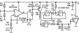
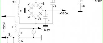
The basic principle of a current-controlled amplifier was first described in The Elector (see Elector #8 and 21). To briefly summarize, his circuit uses the effect of the four passive components (bridge) R2, R3, L and C, shown in Fig. 1, due to which the non-linear characteristic of the output stage becomes unimportant. Thus, it became possible to use a class B output stage (i.e., bias at the bases of the output transistors below the cutoff potential, so their quiescent current is zero) with all its advantages and without its inherent disadvantages (transient distortion) in this design. The circuit shown in Fig. 2 functionally implements the principle of current control described above. According to the author, this UMZCH allows you to get 100 W when operating at a 4 Ohm load, while Kg at a frequency of 1 kHz is stated to be 0.006% with a power of 60 W. If equipment is available that allows accurate measurements of Kg, C3 can be replaced with a 22pF variable capacitor, and the latter is adjusted to minimize distortion. The circuit also contains an innovation in the form of an equivalent load (R9). The output stage is controlled (via transistors T2 and T5) by transistors T1 and T4, connected in series to the positive and negative arms of the op-amp power supply, respectively. This also improves the slew rate of the 741 op amp (meaning LM741 and clones). If, however, a faster op amp is used (such as the LF357), then the ratings of R4 and R7 must be changed to provide enough quiescent current for the op amp to keep the output transistors off. Graham Schmidt (Germany) Despite the fact that the idea itself, in its development, undoubtedly makes it possible to obtain the highest parameters at minimal circuitry and monetary costs, the elementary base used by Schmidt is undoubtedly behind the times today. Today, high-precision op-amps with impressive operating speed and slew rate, powerful low-noise transistors that require almost no pairing, high-frequency diodes with a low opening threshold and inexpensive zener diodes, the voltage accuracy of which is no worse than a fraction of a percent and weakly depends on temperature, have become available. Moreover, these components are now relatively cheap and available. Based on these facts, continuous experiments and searches, changing circuits and boards, an optimal combination of ratings and parameters of the device was obtained, the diagram of which is given below.
ABOUT THE ELEMENT BASE FOR THE STONECOLD AMPLIFIER
OU. The common TL071 was chosen as a musical, high-speed op-amp with a low bias voltage, which is very critical in this circuit, because Without C1, this UMZCH can actually work as a DC amplifier, since it does not contain capacitance in the OOS circuit. The best TL071 I've ever owned was an op amp from Texas Instruments®. The output offset without calibration was no more than 3 mV. For normal operation of the UMZCH, it is necessary that the output offset does not exceed 30 mV. But, since it is not always possible to get op-amps from elite companies, such as TI (Texas Instruments®), NS (National Semiconductors®) and AD (Analogue Devices®), with a low bias voltage, the board provides space for installing a trimming resistor (the value is taken from the datasheet) format CA-6V or similar. Possible replacements (from most preferred to least): Elite op-amps Burr-Brown, etc., TL071 produced by “low” brands such as ST, KR544UD2A, KR544UD1A, KR140UD608, KR574, etc. Replacing the OS will also entail a change in the parameters of the LLC and local environmental protection. Capacitance C2 is installed to compensate for the drop in gain with increasing frequency for the 741 op amp. For the TL071, this unevenness appears far beyond the audio range and therefore does not require correction. One of the Vlab forum members completely excluded this capacitor. I suggest setting a capacitance of about 500-1000pF for the stability of the circuit and jumper JP1, which allows you to disable this correction. Zener diodes were installed in the base dividers of the Emitter Follower (EF) transistors formed by VT1 and VT2. Together with resistors R5 and R6 with a power of 0.5 W, the zener diodes form parametric stabilizers that allow you to change the power supply of the UMZCH within a wide range without recalculating the resistive dividers. For the best result, it is advisable to select zener diodes in pairs according to the stabilization voltage within 12-13V, but always the same. Voltage 15V is unacceptable, because then the op-amp in this circuit may fail or go into an extremely nonlinear mode. My design uses 1N4742A, as a variant of BZX55C12 or domestic ones, but they require selection, because their spread is greater. Diodes also meet modern trends. Together with resistors R15 and R16, diodes D1 and D2 perform the functions of thermal stabilization of the pre-output (VT3, VT4) stage, and also prevent the flow of quiescent current through the transistors of the output (VT5, VT6) stage even when the device warms up significantly. Protection diodes D3 and D4 are provided by 1N4007, but they are installed only if the output super-betta transistors do not have built-in ones. In my case, TIP142/147 has these diodes. When installing transistors of type 2SC5200,2SA1943, diodes D1, D2 must be germanium pulse type D311 or low-power Schottky diodes, it is important that the voltage drop across the forward junction of the diode is 0.25-0.3 V. Diodes D6 and D7, connected in forward bias , in combination with capacitors C4..C7, prevent interference from penetrating into the op-amp power stage, which arises due to the high consumption of the output stage at high power. Transistors. The output stage was left unchanged; its characteristics do not matter. Popular high-frequency transistors BC546/556 were installed in the ED. Limiting resistors R15, R16 were included in the emitter circuits of the pre-output stage, helping to stabilize the quiescent current. In addition, it is convenient to measure the quiescent current using the voltage across these resistors. Its value is 20mA. That. the voltage across the resistors should be 15*0.02=0.3V. The transistors of the pre-output stage were selected according to their sound. All considered options sounded approximately the same in midrange and treble, but the TIP31C/32C manufactured by Fairchild Semiconductors® (Beware of counterfeits!!!) provided not only an excellent vocal picture and detail, but also the most collected and dense bass. For the purpose of thermal stability, in addition to the measures described above, VT3 and VT4 are separated to different ends of the board and each installed on a separate small plate heat sink with a surface area of about 30 cm2. Resistors C1-4 (carbon) or MLT (metal film). All, except those indicated separately, at 0.125-0.25 W. Capacitors C12, C3 – K10-17b; C1, C4, C6, C8, C10 – K73-17; S2 – K73-9. The rest are electrolytes, better than well-known Japanese companies - Rubycon, Mitsumi, Matsushita (Panasonic), Samsung, Sanyo, Jamicon.
SETUP
The setup is performed with the output stage transistors turned off. VT5 and VT6 are soldered last.
The coil is made on a mandrel d=7mm in two layers and contains 9+7 turns of copper wire with a diameter of 0.8mm in varnish or epoxy insulation. Impregnated with Moment glue or paraffin for rigidity. The final result largely depends on the accuracy and quality of the coil. Balancing. To check, first set R7 and R8 to 180 ohms. Connect the power to the amplifier through powerful wirewound resistors (at least 5W) with a resistance of approximately 50-100 Ohms each. This will avoid possible breakdowns, overheating, power supply overload and other problems. Plate heat sinks are installed on the pre-output transistors. The input is short-circuited to ground. Now we supply power to the amplifier and measure the DC voltage at its output. If it is less than 30 mV, then you are lucky and the op-amp does not need to be calibrated. Otherwise, a trimming resistor is installed in the board and with its help the output voltage is set to zero. The value and connection circuit of the trimming resistor are selected based on the technical documentation for the microcircuit.
The quiescent current of the pre-output stage is 20mA. It is installed by selecting resistors R7, R8 until a voltage of 300 mV is obtained on resistors R15, R16. All these resistors must be matched in pairs with the greatest possible accuracy. Start with 180 ohms. For different op-amps and transistors, the ratings can vary from 180 to 330 Ohms. The greater the resistance of resistors R7, R8, the higher the quiescent current of the pre-output stage. Now install the output transistors. They are mounted on a heat sink with an area of about 300 square meters. cm through mica with thermal paste on screws with insulating bushings. Check the quiescent current again. Bridge balance. This step can only be performed if you have an oscilloscope and a generator (can be done from a computer). It is necessary to apply a 15-20 kHz sinusoid to the input. First, set a small level and look at the area near the axis. If there are noticeable “deflections” of the sinusoid, then adjustment is needed. To do this, instead of C3, a tuning capacitor of approximately 30 pF is installed. By changing it, one achieves the disappearance of the area of “undercompensation”. Check the output zero again. The setup is complete!
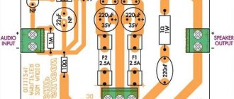
The printed circuit board is made of single-sided foil PCB with a thickness of 1.5 mm. Board size 90x60mm. Below is a layout of elements and a drawing of a printed circuit board for laser ironing technology (LUT). C5 and C7 are installed under the board on the foil side. D6 and D7 – vertically.
Of course, it was impossible to resist not working out the scheme for yourself. First of all, several options for replacing the op-amp were tested. The AD series showed far from its best side - the amplifier became extremely unstable and it was necessary to rewind the inductor several times; of course, before each rewind, various current modes and the selection of a correction capacitor were tested. In general, having played enough, I left the TL071 operational amplifier recommended in the original “Stonecold” circuit. True, TL071 from ST (STMicroelectronics) showed slightly worse parameters, so for this amplifier we purchased TL071 from TI (Texas Instruments). The next batch of experiments was replacing transistors. No, not because the transistors proposed in the original circuit were in short supply. It’s just that 2N5551-2N5401 were purchased in dozens of pieces and I simply didn’t want to expand the list of orders. But TIP31-TIP32 were replaced intentionally. Firstly, the 2SA1837-2SC4793 pair is much faster, they have much higher gain, which ultimately should have a positive effect on the sound quality. Secondly, the TIP31-TIP32 transistors have metal flanges, which means that the transistor will need to be insulated - it is highly not recommended to supply a signal from the collector to the radiator, because it has an output signal amplitude and a current of about 20-40 mA, and this will definitely cause interference. Transistors 2SA1837-2SC4793 have a plastic case and the need for gaskets disappears by itself and you can safely feed a common wire to the radiator. As a result of the replacements, the following amplifier circuit was obtained:
To make it possible to more quickly select current-setting resistors and a correction capacitor, collets from sockets for microcircuits were soldered into the board, and after all the manipulations, the parts were soldered directly into the collets.
The board was also redesigned, but the rework mainly affected the location of the penultimate amplifier stage.
By the time the latest version of the board for Stonecold was developed, the transistors of the final stage had already changed, and not only externally - the amplifier with them became more prone to under-excitement - small RF bursts at the tops of the sine wave at powers close to maximum. I had to add two turns to the coil. Of course, it is necessary to use transistors in the TO-247 package as the final stage, although they are also available in TO-220.
| BUY TRANSISTORS FOR STONECOLD AMPLIFIER |
| 2N5551 + 2N5401 |
| 2SB649A + 2SD669A |
| 2SC4793 + 2SA1837 |
| TIP142 + TIP147 |
SEVERAL PRINTED BOARD OPTIONS FROM THE INTERNET
This printed circuit board has a good layout, but when using this circuitry, it is not entirely correct to attach the transistors of the penultimate stage to a common radiator - heating the common radiator entails a change in the operating modes of the amplifier.
This board is designed for its design features and output power of no more than 60 W, since end-of-line transistors are used in the TO-220 package
Dual channel PCB option
Printed circuit board from INTERLAVKA. The very first option.
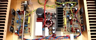
The original amplifier PCB designed by Lincor, below is a photo of what it looks like in metal:
Amplifier printed circuit board using specific heatsinks,
Of course, monoblock designs were also developed based on the STONECOLD amplifier. The first to assemble was a monoblock with a 220V power supply, a level indicator and speaker protection, the schematic diagram of which is given below:
The only weak point of this design was the optocouplers in the preamplifier. These optocouplers maintained the minimum output power from the moment they were turned on for 1-2 seconds, which allowed all transient processes to end. At the moment of transition from applying optocouplers to the LEDs until they were turned off, the sound was quite noticeably distorted. Of course, by replacing the PC817 with OEP optocouplers or homemade ones, this problem can be reduced to NO. More details about homemade optrons:
The PCB design for this version of the power amplifier can be downloaded HERE. The drawing is made in lay format. This monoblock showed itself well not only when working as a subwoofer, but also in a wide range. Well, of course, Stonecold was tested in car audio. The module showed excellent results, and the price-quality ratio made the car owner think about changing the existing amplifier. The schematic diagram of a car amplifier based on “Stonecold” is shown below, the board drawing can be found HERE.
The module has a stabilized output voltage and overheat protection.
Pre-amplifier because there was too much variety on this topic in those days. And finally, the most delicious thing - a video tutorial on how to assemble a STONECOLD amplifier with your own hands and, of course, what kind of power supply it might need: Website administration address
Atomic amplifiers by A. Trusov
I have long wanted to talk about the topic of A. Trusov’s amplifiers. At the Rosshiend exhibition, three years ago, I noticed the nice, eye-catching amplifier cases that many participants used to demonstrate their products. These were A. Trusov’s “Esatto ll” amplifiers. I noticed that they didn’t seem to play badly, but since it was very problematic to draw a conclusion based on the sound at the exhibition, the first acquaintance was very superficial. Whenever I attended Rosshiand exhibitions, I always paid attention to these amplifiers and, whenever possible, compared the sound with other exhibits.
SalonAV magazine
Integrated amplifier AT Audio Esatto II
RULES OF LIFE It’s not very often that Russian manufacturers pamper us with their equipment. Of course, at the “Russian Hi-End” exhibition you can see quite a lot...
I remember the comparison with Ostapov’s Classic Voice KT150 amplifiers on A. Butkarev’s @Maiden boards. I liked the lamp better, but I was already looking with interest at A. Trusov’s amplifiers. At the next exhibition I saw this
I was again hooked by the quality and design of the case! After some time in the “Round Audio” showroom, I slowly, carefully and with pleasure listened to the Esatto amplifier, and having met A. Trusov, I received an invitation to listen to the new Atomico amplifier with acoustics, which was exhibited at Rosshiend (the larger one)
During this action, I caught myself thinking that it would be nice to critically listen to the capabilities of the amplifier on familiar material, but my brain refused to do this! I simply immersed myself in familiar music, which came over me in waves of euphoria and revealed new sides to me! Excellent scene, holography, versatility, resolution and naturalness. Dynamics and subtleties of performance on each instrument and in general. It should be noted that the author tested and listened to the amplifier in various systems, including top-end ones, in which all the roughness and subtleties can be heard very well. After critical comments, the amplifier was modified and listened to again. My impression of the Atomiko's sound is that today it is one of the best transistor amplifiers I have heard. I am writing this quite consciously, having lived with Atomiko and listened carefully to him in different systems. The sound of Esatto is almost the same as in Atomiko, but a class lower. When you listen and get used to the sound of Esatto, everything seems to be quite satisfactory and sounds good, but as soon as you switch to Atomico, you realize how much information and naturalness you didn’t hear, but added on. Technical characteristics of the Atomico amplifier: Output power: 100 W\8 Ohm, 196 W\4 Ohm Bandwidth: 0 Hz - 2.2 MHz (-3 dB) Sensitivity 1.6 V Gain - 35 dB Non-linear distortion at a frequency of 1 kHz and a load of 4 - 8 ohm:
- at low signal level (0.1-1 W) - 0.007%
- at 20 W output power: - 0.025%
- at rated output power (50% of maximum) – 0.055% Volume control range: 63 dB (1 dB step) Balance control: +- 24 dB (1 dB step) Input impedance: 10 kOhm Damping factor: more than 1000 Number of line inputs RCA-2 Number linear inputs XLR-1 Full-featured remote control Supply voltage – 220-240 volts. In general, I propose to trend on this topic. The author @ufotrusov is on the forum, you can ask him questions and inquire about the amplifier tour (Atomico or Esatto).