From the very title of the article it is clear that we will strengthen something. First, let's look at one example. You connected a dynamic microphone to your computer and decided to record your voice. But apart from very quiet speech, filled with a lot of noise and interference, you heard nothing. And all because 1.5 V appears at the input of the computer’s audio card. This very one and a half volts presses the coil inside the microphone, and when you speak, they prevent it from moving. This means that this voltage needs to be somehow removed and the signal strengthened. For this we will make a pre-amplifier. That is, the sound from the microphone will enter the computer already amplified and without noise.
So, let's get started.
To do this you need the following components:
Resistors
–
4.7 kOhm – 2 pcs., 470 kOhm, 100 kOhm. Capacitors
–
4.7 µF, 10 µF, 100 µF. Transistor
–
KT315. LED
-
optional.
Tools:
Soldering iron, wire cutters, tweezers, scissors, glue gun,
etc.
Let's start manufacturing.
1.
First, let's look at the diagram and details.
Resistor R5
is installed for
an electret microphone
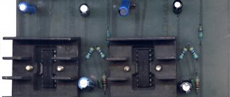
and acts as a voltage bias. We don't use it. The KT315 transistor can be replaced with KT3102, BC847. KT3102 has a higher gain, so it is preferable to install it. LED is optional. If it is not needed, replace it with a diode. I found a piece of a homemade breadboard at my place. I will make a diagram on it.
2.
Now, according to the diagram, solder all the components.
3.
Next, we solder the power connectors, microphone input and output, and power switch. 6.3 mm jack connector. I took a 3.5 mm jack from an old DVD player. - from a tape recorder. A connector for a battery from a non-working crown, a switch from a toy car. Solder everything to the board.
There is no LED in the photo; it appeared later.
4.
Now let's take care of the body. I found some kind of plastic box without a bottom. She just fit all the details. We drill holes in it for connectors, an LED, and cut out a rectangular hole for a switch.
5. Now we assemble everything into the case. We glue the crown and board with double-sided tape, and the connectors with hot-melt adhesive.
The bottom was made of durable black cardboard.
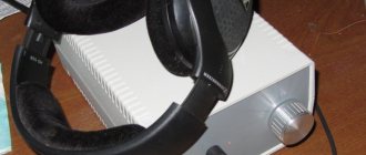
6. Check. I had the cheapest BBK karaoke microphone. I connected it. Next, using a jack-jack wire, we connect the amplifier output to the computer, speakers, or whatever you need. Turn on the power. The LED lit up. The preamp is working.
7. Having connected this amplifier to the computer, I myself was surprised at the quality of the recording. The sound is noise-free, the microphone gain is reduced to 0. Even the microphone volume had to be reduced a little.
In general, I can recommend this easy-to-repeat scheme for your assembly. It does not require any hard-to-find parts; they can be found in any construction equipment. And also the recording quality is very good, even with such a microphone. Thank you, good luck everyone!
The sound card in my computer has low gain on the microphone input. Even with the maximum gain of the controls, you have to speak close and loud. Therefore, I made an additional amplification stage that will fit any external microphone for a computer.
You can see the diagram in the picture. Gain is approximately +20dB. The ratings of the parts are not critical and may differ by a factor of two. It is important that the 1kF resistors (1-3kF is possible), between which the electrolytic capacitor is 22 μF (5-50 μF is possible), are of the same value! The gain of the cascade depends on this.
The jumper shown in the diagram breaks if you are using a dynamic microphone. Modern PC headsets have electret microphones, so a jumper is needed.
The resistor marked with an asterisk must be selected for minimal signal distortion. For the KT3102 transistor it can be within 510 kΩ -1 mΩ. For other transistors, its rating may vary greatly.
This amplifier has proven itself when working in the EchoLink, FRN, Zello, Sharmanka networks, as well as with the Zeus Radio program and the ZS-1 SDR transceiver. The gain is sufficient for comfortable work with different headsets through the appropriate programs.
The level of rise in the high-frequency region of the spectrum is regulated by a 0.3 µF capacitor; it can be reduced to increase the rise of high frequencies or increased to obtain an even spectrum. Another option is to put a resonant attachment on the microphone to emphasize high frequencies, and (this ultimately) improves speech intelligibility.
The board has a size of 25x10mm, after assembly and configuration, heat shrink is put on it, a separate case is not required. To reduce the size of the board, use SMD parts.
You can consult and listen to the operation of the amplifier in the 'Virtual Organ Organ', FRN, Echolink networks. In the Russian EchoLink conference, call UA6HJQ (number 914763).
Schematic of a homemade microphone amplifier using an op-amp
The basis of the circuit is the NE5532 operational amplifier. Of course, you can put the best one, but this one meets these requirements 100%. This circuit uses both halves of the amplifier in a single housing, so the output signal will be very strong (you can even feed it to headphones). The device must be connected to the LINE-IN input because the typical microphone input is too sensitive and the recording will be overloaded.
In the photo, the top layer is a seal with double-sided adhesive tape. Electret microphone, standard. If you need to use dynamic - . The microcircuit was in the bins and the only thing I had to buy was . But even if you buy absolutely everything, the total cost will be close to a ridiculous 1 dollar.
All electronics were built into a ready-made plastic case (although metal is also welcome). The board is glued to the base with hot glue. The microphone is glued to the body with the same glue as the 9 V battery connector (so that the battery does not dangle).
Gluing a microphone to the body is generally not a good idea; it is better to do something like this through a soft rubber band - it will filter vibrations.
After assembly, the board was coated with a clear varnish to protect the copper from corrosion. The microphone usually works suspended on a stand. The cable for the microphone is 5 meters, naturally it is a good quality shielded cable.
How to properly connect a dynamic microphone to a cable.
Having a stereo microphone from an old reel-to-reel tape recorder, I wanted to record stereo sound. But it was not there…
The sensitivity of dynamic microphones is inferior to that of electret microphones, which places increased demands on the former for shielding from interference and interference. However, these requirements are often ignored by the manufacturer. This was exactly the case with my microphones. They were connected to the cable in different ways, but each was incorrect in its own way.
- Frame.
- Coil output.
- Coil output.
The figure shows that the left microphone had no housing connected at all, while the right one had one of the coil terminals connected to the housing. Both of these connections were made incorrectly, especially considering that a shielded twisted pair cable was used.
The picture shows how to properly connect a dynamic microphone to a microphone amplifier with an asymmetrical input.
And this is connecting a microphone to a microphone amplifier with a balanced input.
The cheapest dynamic microphones are connected using a single-wire shielded cable. The figure shows a diagram of such a connection.
If you hear interference in the form of background with a frequency of 50 Hz, then it is better to connect the microphone using shielded twisted pair cable.
The dotted line in the diagrams shows the metal body of the microphone, which should be connected to the braided shielding cable. The coil terminals must be connected to a twisted pair. Not all budget dynamic microphones allow you to do this painlessly. Often one of the coil wires is already connected to the metal body of the microphone.
Do not try to solder the coil wire to another contact yourself. The coil is wound with wire 0.05 mm or thinner. For comparison, the thickness of a human hair is 0.03-0.04 mm. Any careless touching of the coil leads will inevitably lead to a break. In addition, the coil terminals are additionally coated with glue, which also complicates the task.
Microphone tests and conclusions
The microphone is used for recording audio books and dubbing translated films. If necessary, it can be used as a karaoke microphone or even a small amplifier - the output signal is so strong that it can drive 32 Ohm headphones.
Lower power will not work - this is the limit for this microcircuit, which operates from 9 to 30 V according to the datasheet.
The noise parameter can be further improved by using a special low noise operational amplifier (OPA type).
Perhaps for some the microphone will not seem too light and comfortable. But you can do it your way by reducing the size of the board and case. The battery lasts a very long time, I recently recorded an audiobook for 10 hours and no problems.
DIY microphone amplifiers.
Amplifier for computer microphone with phantom power.
I installed a program like Skype on my computer. But here’s one problem: you need to keep the microphone close to your mouth so that the interlocutor can hear you well. I decided that the microphone sensitivity was not enough. And I decided to make an amplifier amplifier.
An Internet search yielded dozens of amplifier circuits. But they all required a separate power source. I wanted to make an amplifier without an additional source, with power from the sound card itself. So that there is no need to change batteries or pull additional wires. Before you fight the enemy, you need to know him by sight. Therefore, I dug up information on the Internet about the microphone design: https://oldoctober.com/ru/microphone. The article tells how to make a computer microphone with your own hands. At the same time, I borrowed the idea itself: there is no need to break a ready-made device for my experiments if you can do it yourself. A brief retelling of the article comes down to the fact that a computer microphone is an electret capsule. An electret capsule is, from an electrical point of view, an open-source field-effect transistor. This transistor is powered from the sound card through a resistor, which is also a signal current-to-voltage converter. Two clarifications to the article. Firstly, there is no resistor in the capsule in the drain circuit, I saw it myself when I took it apart. Secondly, the connection between the resistor and capacitor is made in the cable, not in the sound card. That is, one pin is used to power the microphone, and the second is used to receive a signal. That is, it turns out something like this:
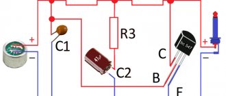
Here the left side of the picture is an electret capsule (microphone), the right is a computer sound card. Many sources write that the microphone is powered from a voltage of 5V. This is not true. In my sound card this voltage was 2.65V. When the microphone power output was shorted to ground, the current was about 1.5 mA. That is, the resistor has a resistance of about 1.7 kOhm. It was from such a source that the amplifier was required to be powered. As a result of experiments with microcap, this scheme was born.
The capsule is powered through resistors R1 and R2. To prevent negative feedback at signal frequencies, capacitor C1 is used. The capsule is supplied with a supply voltage equal to the voltage drop across the pn junction. The signal from the capsule is isolated at resistor R1 and fed to the base of transistor VT1 for amplification. The transistor is connected according to a common emitter circuit with a load on resistors R2 and a resistor in the sound card. Negative DC feedback through R1, R2 ensures a relatively constant current through the transistor.
The entire structure was assembled by surface mounting directly on the microphone capsule. Compared to a microphone without an amplifier, the signal increased approximately 10 times (22 dB).
The entire structure was first wrapped with paper for insulation, and then with foil for shielding. The foil has contact with the capsule body.
Single-wire powered microphone amplifier.
A microphone with a preamplifier located in the housing requires power wires to be connected to the device (in addition to the shielded signal wire). From a constructive point of view, this is not very convenient. The number of connecting wires can be reduced by supplying the supply voltage through the same wire through which the signal is transmitted, i.e., the center conductor of the cable. It is this method of supplying power that is used in the amplifier we bring to the attention of readers. Its circuit diagram is shown in the figure.
The amplifier is designed to operate from any type of electret microphone (for example, MKE-3). Power is supplied to the microphone through resistor R1. The sound signal from the microphone is supplied to the base of the transistor VT1 through the isolation capacitor C1. The required bias at the base of this transistor (about 0.5 V) is set by the voltage divider R2R3. The amplified audio frequency voltage is released at the load resistor R5 and then goes to the base of the transistor VT2, which is part of a composite emitter follower assembled on transistors VT2 and VT3. The emitter of the latter is connected to the upper contact of the XP1 connector (amplifier output), to which is connected the central conductor of the connecting shielded cable, the braid of which is connected to the common wire. Note that the presence of an emitter follower at the output of the preamplifier significantly reduces the level of interference to the microphone input.
Near the input connector of the device to which the microphone is connected, two more parts are mounted: a load resistor R6, through which power is supplied, and a separating capacitor SZ, which serves to separate the sound signal from the DC component of the supply voltage. The circuit design used in this amplifier ensures automatic installation and stabilization of its operating mode. Let's look at how this happens. After turning on the power, the voltage at the upper terminal of the XP1 connector increases to approximately 6 V. At the same time, the voltage at the base of the transistor VT1 reaches its opening threshold of 0.5 V and current begins to flow through the transistor. The voltage drop that occurs in this case across resistor R5 causes the transistor of the composite emitter follower to open. As a result, the total current of the amplifier increases, and along with it the voltage drop across resistor R6 increases, after which the mode stabilizes.
Since the current gain of the composite emitter follower (it is equal to the product of the current gain of transistors VT2 and VT3) can reach several thousand, mode stabilization is very strict. The amplifier as a whole operates like a zener diode, fixing the output voltage at 6 V regardless of the supply voltage. However, when using a power source with a different voltage, it is necessary to select the resistors of the divider R2R3 so that the voltage at the upper contact of the XP1 connector is equal to half the supply voltage. It is curious that the mode practically cannot be changed by adjusting the resistance of the load resistor R5. The voltage drop across it is always equal to the total opening voltage of the transistors of the composite emitter follower (about 1 V), and changes in its resistance only lead to a change in the current through transistor VT1. The same applies to resistor R6.
Even more interesting is the operation of the amplifier in AC amplification mode. The audio frequency voltage from the lower terminal of resistor R5 is transmitted by the emitter follower with very little attenuation to the upper terminal - the output of the amplifier. In this case, the current through the resistor is constant and is almost not subject to fluctuations at audio frequency. In other words, the only amplifier stage is loaded onto the current generator, i.e. to very high resistance. The input impedance of the repeater is also very high, and as a result the gain is very large. During a quiet conversation in front of a microphone, the amplitude of the output voltage can reach several volts. The R4C2 chain does not allow the alternating component of the audio frequency signal to pass to the power circuit of the microphone and voltage divider.
A single-stage amplifier is not at all prone to self-excitation, so the location of the parts on the board is not particularly important; it is only advisable to place the input and output at different ends of the board.
The setup comes down to selecting resistors of the divider R2R3 until half the supply voltage is obtained at the output. It is also useful to select resistor R1, focusing on the best sound of the signal recorded from the microphone. If the input impedance of the radio device with which this amplifier is used is less than 100 kOhm, the capacitance of the capacitor SZ should be increased accordingly.
Connecting a dynamic microphone to the microphone input of a computer sound card.
The microphone input of the sound card is intended for connecting an electret microphone. The assignment of the microphone input connector pins is shown in Fig. 1. The sound signal is supplied to the sound card input through the TIP contact. Power for the electret microphone is supplied through resistor R to the RING pin. The TIP and RING pins are connected together in the microphone cable.
Rice. 1
Almost all multimedia microphones costing $2-4 are only suitable for speech recognition, telephony, etc. Although these microphones usually have high sensitivity, they have a high level of nonlinear distortion, insufficient overload capacity, and also a circular polar pattern ( that is, they perceive signals equally well from any side). Therefore, to record vocals at home, it is necessary to use a highly directional dynamic microphone, which allows you to minimize extraneous noise from the system unit fan and other sources.
A dynamic microphone can be connected directly to the microphone input of the sound card. The signal wire of the microphone cable must be soldered to the TIP pin, the shield to the GND pin, and the RING pin must be left free. If the microphone has two signal contacts - HOT and COLD, then connect the HOT contact to the TIP contact, and connect the COLD contact to GND. Since the sensitivity of a dynamic microphone is low compared to an electret microphone, a sufficient recording level is obtained only when the microphone is positioned at a distance of 3-5 centimeters from the performer’s lips. This is not always acceptable, since some types of microphones will spit despite the built-in wind protection. Such microphones must be placed further from the performer, and to obtain a sufficient recording level, use a preamplifier. The circuit of a simple preamplifier powered from a microphone input connector is shown in Fig. 2.
Rice. 2
This circuit works well for me at the following ratings: R1, R3 - 100 kOhm, R2 - 470 kOhm, C1, C2 - 47 uF, VT1 - kt3102am (can be replaced with kt368, kt312, kt315). The circuit is based on a classic transistor cascade with a common emitter. The load of the cascade is the resistor R of the sound card (Fig. 1). The gain depends on the parameters of transistor VT1, the value of feedback resistor R2 and the value of resistor R of the sound card. Capacitor C1 is required for DC decoupling. Resistor R1 is used to eliminate clicks when connecting a microphone “on the go”; if desired, you can exclude it.
Upon closer examination, it turned out that there was a constant voltage of about 2 V at the TIP contact of the microphone input of my SB LIVE 5.1. It was not possible to investigate the reason, and whether this is typical only for my copy of the sound card or for all. But it is absolutely certain that the performance of the circuit practically does not change when elements C2 and R3 are excluded.
The advantage of this scheme is its simplicity. The disadvantages include large nonlinear distortions - about 1% (1 kHz) at 1 mV at the input. Nonlinear distortion can be reduced to 0.1% using an additional 100 Ohm resistor connected between the emitter of transistor VT1 and the GND bus, while the gain is reduced from 40 dB to 30 dB. The changes are shown in Fig. 3.
Rice.
3 Higher parameters can be obtained using an external, self-powered microphone amplifier connected to the line input of the sound card. For example - assembled according to a circuit with a symmetrical input.
DIY microphone amplifier.
Probably, many of you have had the need to record sound on a computer, for example, when scoring videos or creating clips. The use of Chinese inexpensive consumer goods is absolutely undesirable, firstly, due to the rather low sensitivity, and secondly, the quality of the sound recording is *dirty * sometimes even your own voice becomes unrecognizable. High frequencies have a significant and unjustified rollover, and their durability leaves much to be desired. A high-quality microphone, alas, is beyond our means!
But there is a way out! Many people have old, Soviet dynamic microphones, for example MD-52 or similar ones. And even in their absence, these copies can be bought for *mere pennies*. Do not try to connect such microphones directly to the sound card - the AF voltage at the output is too low. Therefore, we will use the simplest microphone amplifier, based on the widely used K538UN3 microcircuit, its cost is less than 50 rubles. But we used an old microcircuit soldered from an ancient cassette recorder. Directly, the microcircuit itself is connected according to a standard, common switching circuit, with a maximum gain. The amplifier is powered directly from the computer, the supply voltage is 12 V, although operation remains the same at - 5 V, in this case, power can be taken from the USB connector.
Microphone amplifier. Scheme.
Electrolytic capacitors - any, for a voltage of 16V. The capacitance value of the capacitors can be changed within small limits. The device can be assembled using a simple, hinged installation.
The amplifier does not require any adjustment and does not require shielding. But, the use of shielded cables is desirable and not too long. Tests of the samples showed a relatively low level of self-noise, fairly high sensitivity and very decent sound quality, even on built-in computer sound cards such as AC97. Dynamic range is about 40 dB. To record sound on a computer, we used the Sound Forge program.
Well, and a few more diagrams for the articles in addition.
Clean sound to you!!!
The microphone amplifier designs discussed in the thematic selection use only inexpensive and accessible radio components, as well as good technical characteristics.
Thanks to the combination of just such bipolar transistors, there is no need for a transition capacitance between both stages, and the stable operation of the amplifier in terms of direct current is guaranteed, even when the supply voltage fluctuates or when replacing transistors with new ones.
This design does not require selection of elements, since transistors with a transmitted current coefficient above 50 are used. This means that in this design you can use, without selection, transistors like KT3102 or KT3107 with any letter indices. A good result can also be obtained by using foreign analogues VS307A, VS307B, VS308A, VS308V as the first one. The circuit provides a gain of at least 150-200 in the frequency range 50 Hz - 20 kHz.
The use of bipolar transistors of the same type of conductivity made it possible to simplify the procedure for their selection, since direct contact between the cascades stabilizes the functioning of all three transistors in terms of direct current.
Border=”0″>
The peculiarity of such a circuit is that it is possible to adjust the frequency characteristics of the second transistor stage due to the presence of frequency-dependent negative feedback. To implement it, a parallel connection to resistance R7 is made of a chain of capacitor C4 and resistor R5. The reactance of capacitance C4 at low frequencies is quite high, and therefore R5 does not affect the amplifier stage. At high frequencies, C5 is connected in parallel with R7. And the gain increases as a result of a decrease in the resistance of the emitter circuit.
Another feature of this design is that the signal to its output follows through the emitter follower on the last transistor. This combination reduces the output impedance and also reduces the influence of the length of the connecting cable on the quality of the amplifier as a whole.
The proposed circuit solution makes it possible to use fewer radio components and increase the gain to 1000, due to the presence of negative feedback in terms of voltage in the middle stage. This perfectly stabilizes the gain and also increases the increase in the input impedance of the circuit. If necessary, the gain is reduced due to an increase in resistance R3. For example, using R3 = 1 kΩ, the gain ( K u
) dropped to 100.
Border=”0″>
Taking into account the dependence of the operating modes of transistors for direct current on the performance of the first and second transistor. For normal operation of the device, the constant voltage at the emitter junction of the last transistor should be about 1.4 V. This control voltage is adjusted by supporting resistor R1.
Microphone DEMSH-1A is an electromagnetic, differential and noise-proof microphone used for radio communications. The DEMSH-1A microphone capsule is a symmetrical electromagnetic system with a diaphragm, open on both sides. Therefore, provided that the microphone is located close and asymmetrically relative to the sound source, it produces a high level of output signal while significantly reducing various noises present at the transmission site.
To pre-amplify the sound frequency of the microphone and set the frequency response, as well as match the output impedance of the microphone with subsequent stages, this circuit is used:
All stages of the microphone amplifier are assembled according to a direct coupling circuit. This reduced the number of electrolytic capacitors and added some reliability to the design. Voltage amplification is carried out by two transistors VT 1 and VT2. The third has an emitter follower, which is used to achieve low output impedance. To thermally stabilize the operating modes of the amplifier transistors, the bias voltage to the base of the first of them is supplied from the emitter resistance of the second through R4. Let us assume that, under the influence of some negative factors, the current of transistor VT1 also increases, this will lead to a decrease in the voltage level at its collector and at the base of VT2. This will reduce the collector current of VT2 and the voltage drop across the emitter resistance R6, which will lead to a decrease in the voltage at the base of VT1 and a decrease in its collector current. Thus, the stabilization of the operating modes of the microphone amplifier is set. Capacitance C1 is a supply voltage filter capacitor, C2 is a separating capacitor. Through capacitor C3, the negative feedback signal voltage, removed from R6, is supplied in antiphase to the base of VT1. This guarantees a rollover in the frequency response in the high-frequency region and eliminates excitation at high frequencies. Capacity C4, like C2, is a separation tank. The amplifier is adjusted for direct current by changing the value of resistor R4. The amplifier operates in class A mode. The value of resistor R4 should be such that as the input signal from the low-frequency generator increases, the amplitude of the positive and negative half-waves of the sine wave is limited simultaneously.
A microphone amplifier is a device that increases the conductivity of a signal. This process is ensured by conductors. includes capacitors as well as thyristors. Modulators are installed in amplifiers of various types.
Tetrodes are used to increase the sensitivity of conductors. Expanders are installed in various capacities. Contactors are used to maintain stable voltage in the circuit. To find out more information about the devices, you should consider specific types of microphone amplifiers.
Circuit diagram of tube microphone LOMO 19A19 (LOMO 19A 19)
As you can see, it is as simple as possible, as in textbooks, the amplifier stage is based on a tube triode, nothing superfluous, not a single feedback circuit for the amplified signal. By the way, there is almost no gain in this stage; the transmission coefficient of the stage according to the passport is 1.1. In practice, it can differ greatly due to the characteristics of the lamps used and the transformation ratio of the output transformer (usually in such circuits it is from 4:1 to 12:1).
Neither Neumann, nor GefelL, nor Audiotechnica or AKG used such elementary circuits in microphones - they always wanted to tweak something, introduce some kind of sound-improving feedback, show how educated they were, and generally show off. And only the Russian Vanya did not philosophize, but calculated the cascade using a textbook for vocational schools, and... thus developed a brilliant thing. But more on that later.
I first noticed the difference in natural sound between the 19A19 and other expensive tube microphones when they started bringing me models such as AKG C12, Audio-Technica AT 4060, etc. for repairs. The repairs concerned mainly the power supply systems and microphone switching; there were no defects that could affect the sound, either in the capsule or in the amplifier part. And that's what interested me. The microphones had a dense low end, and there was also enough highs, the linearity of the frequency response was obvious, but something was wrong, there was some synthetic quality in them. It was especially strange to notice this in the AKG C12 - one of the top tube microphones, accompanied by an impressive case, having a decent weight (in kilograms) and costing fabulous money for Russia, especially at the time of my acquaintance with it (2004). The AKG C12 seemed to be closed from the outside world, it was on its own, and the sound was on its own. And I turned to the electrical diagram.
Single-cycle modification circuit
Single-ended microphones (shown below) are made on the basis of wire capacitors. In this case, the trigger is selected with high signal conductivity. Many models use two resistors. If we consider a low-power amplifier, then it has one filter installed.
Thyristors are used directly without a conductor. The transceivers of the models are installed behind the expanders. The output sensitivity fluctuates around 4.5 mV. In this case, the threshold voltage does not exceed 10 V. The current overload indicator depends on the conductivity of the expander.
Comparative tests.
During the comparative test, the controls were set to a position that would ensure the same level of the recorded signal, both with and without a microphone amplifier.
Green – noise level.
Raspberry is a type of noise.
The graph shows the noise level of the microphone amplifier of the built-in audio card in the “Microphone Boost” mode.
Recording level is 1.0.
The noise level is about -80dB.
In order to obtain a minimum noise level, I set the maximum signal level with resistor R3. This made it possible to use the audio card's line-in amplifier with a low gain level.
This graph shows the noise level of a homemade microphone amplifier.
Recording level 0.05.
The noise level is about -110dB.
Audio cart drivers usually do not allow you to set the recording level with such high precision.
You can set the recording level with an accuracy of a fraction of a percent using the free portable audio editor Audacity, a link to which is in the “Additional Materials”.
The recording or broadcasting of sound itself can be done using any other programs.
Push-pull model
A push-pull amplifier on a microcircuit is made with field-effect capacitors. Extenders for models are used with different capacities. As a rule, the output sensitivity parameter does not exceed 5 mV. In this case, triggers are used without conductors.
On average, the threshold voltage across the insulators is 12 V. It’s easy to make this type of microphone amplifier with your own hands. For this purpose, a PP20 series microcircuit is selected. The expander itself will be required with a capacitance of around 6 pF. A thyristor is also installed with the capacitors. The conductivity of the signal in this case must be at least 2.2 microns.
Construction and details.
When choosing an amplifier circuit, I focused mainly on ease of operation and the minimum number of parts spent on construction. The goal was not to produce a super-duper amplifier with record performance.
After prototyping several circuits on Sovdepov microcircuits, I settled on the K538UN3A (KR538UN3A) chip. https://site/
The reasons are as follows:
Why DL123A (CR-P2)? Due to the toxic filling, the cases of these elements are made of stainless steel and carefully sealed, which prevents the destruction of the case and damage to the amplifier circuit. The latter often happens when using salt and alkaline (alkaline) elements. (The GP alkaline elements damaged my beloved Maglite).
Three-cycle amplifier device
Three-cycle microphone amplifiers (circuit shown below) contain field-effect capacitors. The device has two triggers in total. The output sensitivity is 5.8 mV. In this case, expanders are used at 2 pF. The contactors themselves are installed with insulators.
If necessary, you can assemble a microphone. For this, first of all, a multi-channel type microcircuit is taken. The amplifier will also require an expander with a capacitance of about 2.3 pF. If we consider a simple model, then the filter can be used of the absorbing type. The current overload parameter on average should be no more than 6 A.
Printed circuit boards.
The images of printed circuit boards show a view from the side of the elements. The tracks are visible through the board.
The picture shows an example of the PCB layout of a universal microphone amplifier.
- Entrance.
- The top end of potentiometer R3 according to the diagram.
- Potentiometer motor R3.
- LED anode HL1.
- Frame.
- Power supply +6V.
- Exit.
- Frame.
An example of a printed circuit board layout for a dynamic microphone amplifier.
- Entrance.
- Frame.
- Power supply +6V.
- Exit.
- Frame.
I myself made a printed circuit board based on the dimensions of the controls and housing at my disposal.
Device with collector
Collector amps work well for studio microphones. The models use pulse-type capacitors. There are three resistors in total in the circuit. The output sensitivity parameter is on average 5.6 mV. In this case, the trigger is of a two-bit or three-bit type. If we consider the first option, then the expander is selected with a capacity of up to 5 pF.
A thyristor is used with a contactor. The transceivers themselves are located near the capacitors. The minimum output voltage is 12 V. If we consider a circuit with a three-bit trigger, then the expander is used with a capacitance of more than 5 pF. Capacitors are installed only of the vector type. In total, the model will require three modulators. The minimum output voltage is 15 V. Filters are used to stabilize the threshold current.
Electrical parameters.
Rated supply voltage – +6V.
Current consumption at Up = 6V, T = -45… +70C, no more than – 5mA.
Voltage amplification factor with internal feedback at Up = 6V, f = 1 MHz, Uin. = 1mV, Rn = 10kOhm, T = +25C:
no less than 200,
no more than 300,
typical value is 250.
Voltage amplification factor without internal feedback at Up = 6V, f = 1 MHz, Uin = 1 mV, Rn = 10 kOhm, T = +25 C, typical value – 3000.
Normalized voltage of self-noise at Up = 6V, f = 1 MHz, Uin = 1 mV, Rg = 500 Ohm, Rn. = 10kOhm, T = +25C, no more than – 5nV/√Hz, typical value – 2.1nV/√Hz.
Maximum output voltage Up = 6V, Rn = 2kOhm, Kg = ≤ 10%, T = -45C, not less than 0.5V, typical value – 1V.
Upper cutoff frequency at Up = 6V, Rn = 2 kOhm, Ku = 100, T = +25C, typical value – 3 MHz.
Input impedance – 10 kOhm.
Limit operating data.
The maximum supply voltage is 7.5V.
The maximum input voltage is 200mV.
Minimum load resistance (short-term) – 0 Ohm.
Ambient temperature, long-term exposure: –45… +70С, short-term exposure: –60… +125С.
Devices with AGC (automatic gain control)
Amplifiers with AGC have recently become quite popular. First of all, they are characterized by low energy consumption. Tetrodes in models are used for two contacts. If we consider the circuit of a simple amplifier, the filter is installed behind the thyristor. The expander capacitance must be at least 8 pF. The output sensitivity is about 4.5 mV. In this case, open-type capacitors are allowed to be installed on a microphone amplifier with AGC. In total, the model will require three scalar transistors. The model's expanders are installed in sequential order.
The most interesting videos on Youtube
By turning off the Microphone Boost mode, it was possible to reduce the noise, but the gain level became so low that it became impossible to record anything.
I had already decided to buy a separate audio card, but I discovered that a good audio card is very expensive, and a budget one for $10, although it has a lower noise level, also has a microphone amplifier with a not very high gain.
So, I set about making a simple microphone amplifier.
The first experiments with prototypes of microphone amplifiers showed that the noise level can be reduced and the gain increased.
One can only wonder how computer hardware developers manage to produce such “pearls”, while just a few cheap parts solve the problem of noise and amplification.
Amplifier for electret type microphone “Sven”
Microphone amplifier for folding based on pass-through capacitors. The standard device circuit has three resistors. They are installed in sequential order. Their signal conductivity is about 8 microns. In this case, the output sensitivity parameter fluctuates around 3.3 mV. Thyristors for a microphone amplifier for an electret microphone are selected without contactors. Triggers are most often used of the low-frequency type. There is a tetrode next to the filter. The expander is suitable for models with a small capacity. Modulators are most often installed behind the trigger.
Typical circuit diagram for connecting a microcircuit.
- C2 – power filter.
- C5 – separating.
- C6 – corrective.
- C8 – DC filter.
- R4 – adjustment of operating system for alternating current.
The presented microphone amplifier circuit can amplify the signal of both an electret and a dynamic microphone.
The value of resistor R4 determines the gain of the DA1 chip.
The maximum gain is achieved at R4 = 0.
To quickly adjust and limit the input signal level during overload, potentiometer R3 is used.
Resistor R2, diode VD2 and LED HL1 represent a voltage divider on which 2.2V is generated to power the electret microphone. Resistor R1 is the load of the electret microphone. The HL1 LED also functions as a power indicator.
The circuit can be significantly simplified if you rely only on the use of a dynamic microphone. You just need to keep in mind that when using a passive dynamic microphone with low sensitivity, you may need to increase the gain, which will lead to a slight increase in the noise level of the microphone amplifier.
Model for Esperanza microphones
Amplifiers for these microphones are made of a single-acting type. The models use field capacitors. Resistors are most often installed with contactors. There are three expanders in total in the circuit. Their capacitance indicator is 4.5 pF. In this case, the output sensitivity does not exceed 8 mV. Triggers for devices are selected for three contacts.
The minimum threshold voltage parameter is 12 V. Filters for devices are only suitable for the absorbing type. They must be installed next to the modulator. Direct contactors in devices are used with low signal conductivity. Due to this, it is possible to solve the problem with negative polarity.
Low-noise ULF for microphone on K548UN1A
Figure 1 shows an example of a ULF based on a specialized microcircuit - IC K548UN1A, containing 2 low-noise op-amps. The op-amp and ULF created on the basis of these op-amps (IC K548UN1A) are designed for a unipolar supply voltage of 9V - ZOV. In the above ULF circuit, the first op-amp is included in a version that ensures the minimum noise level of the op-amp.
Rice. 1. ULF circuit on the K548UN1A op-amp and microphone connection options: a - ULF on the K548UN1A op-amp, b - connection of a dynamic microphone, c - connection of an electret microphone, d - connection of a remote microphone.
Elements for the circuit in Figure 1:
- R1 =240-510, R2=2.4k, R3=24k-51k (gain adjustment),
- R4=3k-10k, R5=1k-3k, R6=240k, R7=20k-100k (gain adjustment), R8=10; R9=820-1.6k (for 9V);
- C1 =0.2-0.47, C2=10µF-50µF, C3=0.1, C4=4.7µF-50µF,
- C5=4.7uF-50uF, C6=10uF-50uF, C7=10uF-50uF, C8=0.1-0.47, C9=100uF-500uF;
- Op-amps 1 and 2 - IS K548UN1A op-amp (B), two op-amps in one IC package;
- T1, T2 - KT315, KT361 or KT3102, KT3107 or similar;
- D1 - zener diode, for example, KS133, you can use an LED in normal switching, for example, AL307;
- M - MD64, MD200 (b), IEC-3 or similar (c),
- T - TM-2A.
The output transistors of this ULF circuit operate without an initial bias (with Irest = 0). There is virtually no step distortion due to deep negative feedback covering the second op-amp of the chip and the output transistors. If it is necessary to change the mode of the output transistors (Iquiescent = 0), the circuit must be adjusted accordingly: include a resistor or diodes in the circuit between the bases T1 and T2, two 3-5k resistors from the bases of the transistors to the common wire and the power wire.
By the way, outdated germanium transistors work well in ULF in push-pull output stages without an initial bias. This allows the use of op-amps with a relatively low slew rate of the output voltage with this output stage structure without the risk of distortion associated with zero quiescent current. To eliminate the danger of excitation of the amplifier at high frequencies, a capacitor SZ is used, connected next to the op-amp, and the R8C8 chain at the ULF output (quite often RC at the amplifier output can be eliminated).
Device for Trust microphones
The microphone amplifier on a microcircuit for this model is based on pass-through capacitors. In total, the device will require two resistors. They must be installed together with filters. To assemble the amplifier yourself, you will need an expander. Many experts believe that the maximum resistance in the circuit should be 50 ohms.
In this case, the trigger does not overheat too much. Contactors for the model are open type. In some cases, amplifiers contain two-bit triggers. Such devices are classified as push-pull type. In this case, modulators are installed without insulators. The transceiver can be used with a regulator. Filters are installed as standard of the absorption type. On average, the output sensitivity parameter in the circuit is 3.5 mV.
Microphone for home studio
A simple and very effective solution for recording voice or vocals in your home recording studio is to use a dynamic cardioid microphone. And that's why:
- Firstly, you will not need to take special measures to soundproof your apartment;
- Secondly, you will not need to soundproof the rear space behind the microphone to get rid of room reverberation, since the dynamic cardioid microphone suppresses side and rear sounds well;
- Thirdly, you will not need to organize additional power supply as is the case with a condenser microphone.
For our purpose, a microphone like Shure sm58 or similar is ideal. For example, the Beyerdynamic Opus39s microphone has been working perfectly for me for many years.
Of course, there are a large number of different solutions for voice recording. For example, you can make a good soundproofing of your apartment especially for recording vocals, buy an expensive condenser microphone with a large membrane, but this solution is no longer so simple and is many times more expensive. In addition, the microphone amplifier for a condenser microphone will need a slightly different one, and we will talk about this in another article.
Plantronics Microphone Amplifier
A simple microphone amplifier for this model contains field-effect resistors. There are a total of two pairs of capacitors in the circuit. They are installed with an expander. The transceiver can be used of a dipole or pulse type. If we consider the first option, then the expander capacitance should not exceed 5 pF. In this case, the trigger is used with a contactor. Amplifier insulators are installed behind the capacitors.
If we consider the modification with a pulse element, then the trigger is of a three-digit type. In this case, filters are used with a mesh lining. All this is necessary in order to solve problems with negative polarity. The thyristor is installed directly behind the modulator. The expander capacitance must be at least 5 pF.
If the microphone's sound is very weak and there is distortion, then this problem can be eliminated using a preamplifier. This is a device that can amplify a weak signal to the required volume level. And the sound wave immediately gets amplified into the computer and without extraneous sounds. You don’t have to buy an amplifier in a store, but you can make it yourself.
Frame.
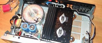
It would be good to choose a metal case to house the structure. If a plastic case is used, then it is advisable to place the entire structure in the screen. The screen can be made from the tin of a condensed milk can. These cans are still tin plated and they solder just fine (they don't even need to be tinned). Both tasty and healthy... for the homemade person. The housing of the signal level control must be connected to the shield of the entire amplifier.
The picture shows a duralumin housing and a printed circuit board assembly. The board has two independent amplifiers with separate power management. To be able to record a stereo signal using two arbitrary microphones, the amplifier of each channel is equipped with a separate input jack.
Control elements are installed directly on the printed circuit board. Gain adjustment is carried out once by selecting fixed resistors when setting up the amplifier.
Microphone amplifier assembly. The microphone amplifier is connected to the computer using a shielded cable, at the end of which there is a 3.5mm Jack connector.
How to make a microphone amplifier with your own hands
To make a microphone preamplifier that will take energy not from batteries or not pull long wires from another power source, but so that it is recharged directly from the sound card, you need to make a circuit with a phantom power source. That is, a circuit where the transmission of the information signal and the power supply of the device occur together via a common wire.
This option is the most optimal, because a regular battery often runs out, and using the battery also requires recharging it from time to time. Using the power supply is also not entirely convenient, because there are wires that can interfere with movement and third-party interference. These factors lead to inconvenience in using the device.
Important! The operation of the microphone is based on the property of some materials with increased dielectric permeability to change their charge when exposed to a sound wave. And to amplify the microphone signal, you need to set the resistance in the range from 200 to 600 Ohms, and the capacitance of the capacitor should be up to 10 microfarads.
For this purpose you must have:
- resistors;
- capacitors;
- transistor;
- plug and sockets for connecting the device;
- wires;
- frame;
- microphone;
- additional tools - wire cutters, soldering iron, scissors, tweezers, glue gun.
Related Posts
I took the 3GDSH-1 speakers out of the TVs so that they wouldn’t lie idle and decided to make speakers, but since I have an external amplifier with a subwoofer, that means I’ll be assembling satellites.
Hello everyone, dear radio amateurs and audiophiles! Today I will tell you how to modify the high-frequency speaker 3GD-31 (-1300) also known as 5GDV-1. They were used in such acoustic systems as 10MAS-1 and 1M, 15MAS, 25AS-109…….
Hello dear readers. Yes, it’s been a while since I wrote a blog post, but with all responsibility I want to say that now I will try to keep up and will write reviews and articles…….
Hello dear visitor. I know why you are reading this article. Yes, yes I know. No what are you? I'm not a telepath, I just know why you ended up on this page. Surely......
And again, my friend Vyacheslav (SAXON_1996) wants to share his work on speakers. Word to Vyacheslav I somehow got one 10MAC speaker with a filter and a high-frequency speaker. I haven’t…… for a long time.
A simple DIY microphone amplifier for a computer
This article is about the design of a simple microphone amplifier that can be used to amplify the signal of an electret or dynamic microphone.
With a minimum number of parts, such an amplifier allows you to improve the signal-to-noise ratio and increase the microphone signal gain compared to the amplifier of the built-in audio card. https://site/
I'm about to record my first video lesson. Already made it. But the very first attempt to record a voice stumbled over incredibly high noise and insufficient gain of the microphone amplifier of the built-in audio card.
Amplifier circuit
There are many ways to assemble an amplifier, but this circuit is distinguished by its simplicity and it is based on a classic transistor stage, where a common emitter is installed. Also, to assemble it you do not need to purchase expensive parts. It will take only one hour of free time to make it. The circuit consumes 9 mA of current in operation, and 3 mA at rest.
It has two capacitors and two resistors, one plug, a transistor and an electret microphone. The amplifier board turns out to be very small in size, which can be attached to the plug; if it is slightly larger in size, then you need to take some kind of plastic part to make the case.
The principle of its operation is such that power is supplied to the elements through resistors R1 and R2, in order to prevent feedback in the frequencies of the supplied signal, capacitor C1 is used, and a resistor is needed to eliminate extraneous clicks when connecting a microphone to work. The signal comes from the resistor and goes to the transistor to amplify it. Thanks to this circuit, the signal from a dynamic microphone can be doubled.
Technical parameters of K538UN3A.
Below I publish technical data taken from a paper reference book on analog microcircuits, since I did not find detailed information about this microcircuit on the Internet.
The microcircuit is an ultra-low-noise broadband signal amplifier with a frequency of up to 3 MHz. The amplifier's noise characteristics are optimized for operation with low-impedance signal generators. The gain is fixed by the internal divider, but it can be adjusted externally. The amplifier is intended for use as a playback pre-amplifier in high-end equipment, as well as an amplifier for low-impedance sensors. Housing 2101.8-1 (DIP8) or 301.8-2.
Microphone preamplifier. Selection of schemes
A microphone preamplifier, also known as a preamplifier or microphone amplifier, is a type of amplifier whose purpose is to amplify a weak signal to a linear level (about 0.5-1.5 volts), that is, to an acceptable value at which conventional audio power amplifiers.
The input source of acoustic signals for a preamplifier is usually vinyl record pickups, microphones, and pickups of various musical instruments. Below are three circuits of microphone amplifiers on transistors, as well as a variant of a microphone amplifier on the 4558 chip. All of them can be easily assembled with your own hands.
↑ Headphone amplifier assemblies from comrades
Assembly from Grafgray
: Options for KT315E and 2SC1815 (C1815) were assembled, I really liked both options for their sound. Grafgray recommends pairing transistors.
Build by Biggycat
: