Modern headphones have everything a lover of high-quality sound might need. But there is one thing missing - the soul. Many audiophiles will agree that warm analogue sound is much better than modern digital sound. But such a sound is produced not only by the appropriate amplifier, but also by authentic headphones. Some music lovers believe that there is nothing better in the world than Soviet headphones (and audio equipment in general). Oddly enough, there are quite a lot of such people. And all of them still enjoy using Vega (or Amfiton) amplifiers, Radiotekhnika speakers and TDS-3 headphones. By the way, it’s worth talking about the latter separately. For they symbolize an entire era. Let's start with a general description of the model and touch a little on its history.
General description of headphones
TDS-3 headphones were first released in 1984 by the legendary Soviet concern Electronics. At that time they were a breakthrough in the Soviet sound industry. And this is not surprising, since the technical characteristics (and the design itself) were blatantly copied from similar headphones produced by Yamaha. In principle, this was common practice in the USSR. And no one hid this. Nevertheless, the TDS-3 sold well (probably due to the complete lack of alternatives) and had good sound. Today, headphones of this type do not look very attractive. But not for those who love vintage. It is worth noting that TDS-3 is the best-selling item at modern domestic flea markets. Audiophiles believe that they can use them to achieve that very “legendary” sound. It's possible. But only if you use an old vinyl player and fairly scratched records. However, we got carried away. Let's move on to the review of vintage headphones from 1984.
Electronics TDK-3
0
A little exotic in our selection, namely a rare model of quadraphonic headphones “TDK-3 Quadra”, which was produced in the USSR since 1979. Today we are already well acquainted with modern surround sound formats, but in the distant 70s, quadraphony was a novelty and promised to become an interesting technology, although it could not gain much popularity in those days. Apparently, the fashion for quadraphony in the USSR ended before it even began, but the TDK-3 headphones can be considered one of the most interesting models that were produced in Soviet times. When developing these headphones, the quadraphonic models that were produced at that time in Japan were taken as a basis: Fisher DR-147Q and Panasonic EAH-41. The design of the TDK-3 used 4 dynamic drivers 0.25GD-10, which provided interesting surround sound. The package also included a special adapter that connected to the headphone plug and allowed you to listen not only to quadraphonic, but also stereo and mono recordings. Perhaps the main drawback of this model was the ergonomics, namely the weight of the headphones, which was no less than 800 grams! Probably, TDK-3 could have become popular even in the absence of special players and quadraphonic recordings on sale, since the headphones could also be used for listening in stereo, but the excessively large weight (like their Japanese counterparts) negated the advantages of this model. After the release of the TDK-3 in 1979, there was no noticeable increase in interest in quadraphony, and the first batches of these headphones were sold out in Soviet stores with some difficulty.
Appearance and Design
Soviet TDS-3 headphones have an outstanding design. At least he was like that at the time of their release. Oblong cups, thick plastic, no hint of an open design. The ear pads are made of soft and elastic material covered with artificial leather (or something similar to it). The color of the headphones could be very different: from pale green to red. There were also black models. But most of all were yellow. The phone holder was made of metal, but was covered with faux leather. Inside this very skin there was a semicircular perforated material that gave softness. Thanks to this, I could wear headphones for a long time and not be afraid of getting a headache. And now you can move on to the technical characteristics of the TDS-3 headphones. They are quite interesting, as they can give an idea of the quality sound of the past.
Main technical characteristics
The Soviet TDS-3 headphones, the characteristics of which we are now considering, at one time belonged to the Hi-Fi category of audio equipment. This means they should have had decent parameters. And that's almost true. With one small exception: the TDS-3 of the original design had simple paper speakers installed, which a priori could not create high-quality sound. Yet somehow these headphones managed to sound decent. It's probably all about the characteristics. The range of reproduced frequencies is 20 - 20,000 Hz. This is an excellent result. Not all modern headphones can boast of this. The nominal resistance is only 8 ohms. This suggests that even a laptop can rock these headphones. Without any amplifier. True, there will be no sound from the built-in video card. The rated power of both speakers is 1 mW. This is unrealistically high for headphones. These are the main technical characteristics of the TDS-3 headphones. Now we can move on to describing the sound quality.
TDS-5
0
TDS-5 headphones went on sale in the early 80s, and despite the fact that they were almost a complete copy of the Japanese Yamaha HP-1, they are a very interesting and noteworthy model. TDS-5 was equipped with semi-open type bowls, which combined the advantages of open and closed acoustic design, and orthodynamic drivers with membranes made of polyester film made it possible to achieve balanced sound in a wide frequency range. The headphone resistance was 100 Ohms, the nominal power was 3 mW, the maximum was 100 mW. As for the appearance of the TDS-5, here (taking into account the fact that the headphones were almost completely copied) the famous Italian designer Mario Bellini distinguished himself, who collaborated with Yamaha and actively participated in the design of those same HP-1 headphones. He managed to create a truly interesting device, with outstanding ergonomics by the standards of those years. Largely thanks to the successful design, the Yamaha HP-1, and then the TDS-5, were in great demand at one time. The TDS-5 headphones were distinguished by a fairly smooth frequency response and natural sound without clearly noticeable coloration, which was good quality not only for listening to music for pleasure, but also for professional monitoring. Since 1987, an improved model was produced in the USSR - TDS-5M, which had slightly different characteristics, and instead of the SSh-5 plug there was a more current Jack 6.3 mm.
Sound quality
So, let's move on to the most interesting part - the sound quality that these headphones provide. Not to say that everything was gorgeous. Paper speakers predictably spoil the whole picture. When playing any genre of music, an acute lack of low and high frequencies is noticeable. Only the middle ones stand out well. All this makes the sound flat and lifeless. The only thing you can listen to with these headphones is audiobooks. Although even there they will not be able to master the full sound coloring of the reader’s voice. In general, the sound is of poor quality. However, this is just the beginning. After opening the headphones, it was noticed that the factory wires (thin and extremely poor quality) were almost completely rotten. It was decided to replace them with new ones. High-quality modern wires were installed. And then the headphones began to sound! Depth, the required bass and excellent high frequencies appeared. All that was required was to change the wiring. In general, the TDS-3, the characteristics of which were discussed a little higher, turned out to be not so simple and were still able to produce high-quality sound.
A tube amplifier is built into the TDS-2 headphones
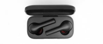
It should be noted that almost all owners of various types of headphones of those times, one way or another, at least once carried out their modification. This time it was decided to produce active stereo telephones with a Bluetooth receiving module and an ultrasonic sounder with output stages based on miniature rod tubes.
The rated output power of such an ultrasonic sounder is 2×10 mW, the measurement was carried out with a wattmeter purchased at an electrical goods store. The effective operating frequency range in terms of sound pressure is 63... 16000 Hz (assessed by ear without a noticeable drop in the signal level). The UZCH uses 1Zh29B-V lamps operating in class A mode. These lamps have a number of advantages, and therefore, like other Soviet-made 1.2/2.4 V rod lamps [3, 4], they enjoy well-deserved popular, in particular, among German radio amateurs [5-7].
Firstly, this is a low filament current (66 mA for 1Zh29B-V), which is very important in our case from the point of view of autonomous power supply. Secondly, the inflection point of the anode current-voltage characteristic for most rod lamps lies in the range of 15...20 V. Therefore, at a low anode voltage, they provide satisfactory linearity and high efficiency in power amplifiers.
Thirdly, at low values of the anode operating current (several milliamps), the effect of magnetization of the magnetic circuit of the output transformer practically does not appear and the efficiency of the cascade increases. Fourthly, the optimal position of the operating point is set automatically due to the constant filament voltage at the cathode.
However, most types of such lamps do not require additional bias to be supplied to the control grid. And finally, the operating temperature of the 1Zh29B-V lamp cylinder does not exceed +40 °C, which allows them to be placed directly in the headphone housing without taking special measures for heat removal and installation.
The current level of development of voltage converters makes it possible to obtain a voltage of 24...27 V or more when powered from DC voltage sources of 3...5 V. A voltage of 24...27 V is sufficient for the normal operation of some types of lamps, provides sufficient linearity of the cascade and at the same time limits maximum output power and, consequently, sound pressure at the level recommended by SANPiN when listening to musical works [8].
Thus, it becomes possible to use common Li-ion batteries with a nominal voltage of 3.7 V, size 18650, to power the device. The device diagram is shown in Fig. 1. The output stages are assembled according to a standard circuit using lamps VL1, VL2 in a pentode connection. Resistors in the circuits of the shielding grids have a significantly lower resistance compared to the standard one, which is due to the reduced anode voltage.
Step-down transformers for power supplies on W-shaped magnetic cores are used as output transformers. This decision is due to the following considerations. Since the output stage operates in class A mode, and due to the low power, the possibility of saturation of the magnetic circuit is excluded, sectioning the windings is not required. There is practically no DC bias, so you can use a magnetic core without a gap.
The desire for maximum reduction of material and time costs is also satisfied. The first feature of the ultrasonic sounder is the circuit for switching on the lamp filament. For direct current, the filament halves of each lamp are connected in parallel, with a filament voltage of 1.2 V applied to the “middle” point (pin 1) relative to the “external” pins 4 and 6.
This, as already noted, sets the operating mode of the lamp. And the filament circuits of the first and second lamps in relation to the power source are already connected in series. Thanks to this, it becomes possible to maintain the filament current of 66 mA, doubling the voltage of the filament power supply to 2.4 V. For alternating current, the cathode of the lamp VL1 is connected to the common wire through capacitor C5.
Its capacity must be large enough to ensure a uniform frequency response in the low-frequency region. Resistor Ya may be needed to equalize the cascade currents by slightly adjusting the filament voltage of one of the lamps. AF signals are supplied to the control grids of lamps VL1 and VL2 through capacitors C3 and C6 from the Bluetooth module A3. This module can be anything with an output voltage of 34,200 mV and suitable dimensions that allow it to be placed in the device housing.
Most of these modules meet these conditions. However, it should be borne in mind that, as a rule, they have an increased level of interference and spurious emissions, and radio amateurs often face the problem of coordinating them with external UMZCHs. This manifests itself in the form of constant “itching” and other extraneous sounds of abnormal intensity, clearly audible in pauses between phonograms.
The only effective measure is to power the A3 Bluetooth module from a separate power source in combination with an RF filter on the inductor, two windings of which are connected to the signal circuit break, and the third is between the common wires of the ultrasonic amplifier and the module. The RF interference signal from the output of the A3 Bluetooth module is effectively suppressed. since it enters the inductor windings in antiphase.
The implementation of this method is the second feature of the device. In the diagram, this is inductor L1, which has three windings (one in the common wire circuit, two signal windings for each channel). In the author's version, a Bluetooth module (9) is used, combined on one board with an integrated ultrasonic frequency class D on a RAM8403 chip (10). The signals of the left (L) and right (R) channels are removed by connecting respectively to pins 7 and 10 of this chip.
The UMZCH function is preserved, and its powerful outputs are routed to additional external connectors installed on the device body (not shown in the diagram, since in the general case their presence is not necessary). Thus, this device can be used in the same way as a compact Class D amplifier with an output power of 3 W per channel. For this purpose, sockets are installed on the body (not shown in the diagram).
Note that the use of a low-quality receiver can make the problem of increased interference insoluble. In this case, it makes sense to remember the good old method of wirelessly transmitting sound with high quality via a VHF radio channel. This method can be implemented using a miniature VHF stereo receiver placed in a phone case and a VHF transmitter, for example, described in [11].
The cost of components is comparable for both cases, but the ease of use and versatility of the method with a VHF channel is somewhat lower. On the other hand, it becomes possible to listen to radio broadcasts. The tube stages are powered by a G2 battery. A voltage converter A4 (12] or similar with an output voltage of 27 ± 3 V is used as an anode voltage source. The current of each lamp anode is 1.1 ± 0.1 mA.
To power the filament circuits, a simple voltage stabilizer on transistor VT1 is used. The blue LED HL1 with a direct voltage drop of 2.8 V is used as a reference voltage source, which simultaneously serves as a power indicator. From the VT1 emitter, a voltage of 2.4 V is supplied to the lamp filament circuit. Capacitor C5 serves to eliminate inrush currents when turned on.
The A4 Bluetooth module is powered by a separate G1 battery of size 16340 with smaller dimensions and capacity. Moreover, both batteries are equipped with separate power switches SA1 and SA2, which makes it possible to use the built-in Bluetooth ultrasonic module without turning on the tube amplifier.
Another useful function of the A3 Bluetooth module is monitoring the voltage of the G1 battery. When it drops below the limit level, a characteristic warning signal is periodically generated. The degree of discharge of the G2 battery is determined indirectly by the brightness of the indicator and the maximum sound volume.
A hardware volume control is provided on the device, since this function, like the equalizer, is usually implemented in software in the signal source. Batteries G1 and G2 are charged from two identical charging controllers A1 and A2 [13]. Their power circuits are independent, and each of them is equipped with its own connector for connecting a charger (XS1 and XS2, respectively).
When charging, of course, the contacts of the corresponding switch SA1 and SA2 must be closed, the external power source used to power controllers A1 and A2. must provide a voltage of +5 V at a load current of up to 1 A. The total current consumed by the device is 75 ± 5 mA, which corresponds to an operating time without charging the battery of at least 30 hours.
Details: Transistor - any silicon n-p-n structure with a permissible collector current of at least 100 mA, power dissipation of 0.5 W or more (without heat sink) and a static current transfer coefficient of more than 50. Oxide capacitors - K50-35, K50-68, the rest are ceramic K10-176 or similar imported ones. Fixed resistors - S2-23N, S2-ZZN, MLT or imported MF. Choke L1 is wound with an insulated mounting wire on a ring ferrite RF magnetic core from the CFL driver.
The winding is made of three wires without twisting, is evenly distributed over the surface of the ring and contains 10...20 turns of insulated single- or multi-core wire with a copper cross-section of 0.1-0.25 mm². The number of turns is selected based on the maximum suppression of interference from the Bluotoolh module.
Batteries of standard sizes 18650 with a capacity of 2400...3600 mAh (G1) and 16340 with a capacity of 500...2200 mAh (G1) are used. It should be noted that the second type battery cannot be replaced by a Li-ion galvanic cell of size CR123 despite the identical dimensions. The nominal voltage of this galvanic element is 3 V, which is not enough for the Bluetooth module to operate.
Toggle switches P1TZ-2V, P1T1-1V, P1T4-2V, MT-1V or any miniature ones, with a maximum switching current of at least 1 A. Power connectors XS1 and XS2 - 2.5 mm sockets DJK-048 (DS-026). Transformers T1 and T2 are network, step-down, with a secondary winding voltage of 9 V with a tap in the middle and an output current of up to 200 mA. They are made on armored plate magnetic cores, similar to standard size Sh-9 with a central rod width of 9 mm, a height of 22.5 mm and overall plate dimensions of 36x31.5 mm.
The thickness of the set is 12 mm. The primary winding contains 5600 turns of enameled high-strength wire (analogous to PEV-1) with a diameter of 0.06 mm. The secondary winding is 2x115 turns of a similar wire with a diameter of 0.25 mm. Winding - layer by layer, turn to turn. The primary and secondary windings are placed in separate sections on a plastic frame. The recommended dimensions of the transformer are about 35x30x30 mm.
It should be noted that standard size Ш-9 is not common. However, it exists and is often found in imported transformers. An expanded list of sizes of typical W-shaped transformer magnetic cores is given in [14] or [15]. The closest is the standard size Sh-10a (Table 2 in [16]). When using it, you do not need to make any changes to the TVZ wire data.
The use of a transformer with smaller dimensions will, naturally, be accompanied by a decrease in the inductance of the primary winding and a “blockage” of low frequencies, as well as an increase in leakage inductance and, accordingly, a deterioration in the sound at HF. When connecting a load with a resistance of 8 ohms, only half of the winding is used. Full inclusion of the secondary winding can be used when using other drivers with 32 ohm coil resistance.
If you plan to use only half of the secondary winding, it is advisable to replace it by winding 100 turns with PEV-1 0.47 wire in order to reduce the DC resistance. If you use a standard winding, for the same reason you should use a part with less resistance.
Adjustment: it is not necessary to select lamps according to the anode and filament current, although this, of course, contributes to better symmetry of the cascades and improved channel balance. Typically, the anode current is automatically set in the range of 1.1 ± 0.2 mA, and its adjustment in the range of ± 10% is achieved by connecting a resistor R parallel to the filament of a lamp with a large anode current and selecting this resistance. For example, such a connection of a resistor for a VL2 lamp is shown in Fig. 1.
Before turning on the incandescent circuits, the VT1 emitter is connected to the common wire through an equivalent load (a resistor with a power of 0.5 W and a resistance of 43...100 Ohms) and make sure that the voltage at the VT1 emitter is 2.4 ± 0.2 V. If necessary, achieve the required voltage by selecting a resistor R1 in the range of 43..130 Ohms and replacing the HL1 LED or connecting an additional KD522B diode (1N4148) in series with it.
Before connecting the anode circuits, you need to set the output voltage of the A4 voltage converter to 27 ± 3 V. The functionality of charging modules, batteries and the compliance of charging modes [17-19] is ensured before installing them in headphones.
Design. The device, as is already clear from the description, has a modular design, which fully complies with the recommendations (4] and differs from the classic block design of tube amplifiers. The relative arrangement of modules and individual elements inside the cases is shown in Fig. 2 and Fig. 3 In the case of the left phone ( Fig. 2) In addition to the dynamic head 1, there are batteries 2 and 3, power switches 4 and 5, charging controller modules 6 and 7, power connectors 8 and a transformer 9.
The body of the right phone contains a dynamic head 10, an ultrasonic sounder board 11 with a filament voltage stabilizer and a power indicator 12. A Bluetooth module 13, a voltage converter 14 and a second transformer 15, as well as a choke 16 and output connectors for an integrated ultrasonic sounder 17. The tube ultrasonic sounder is assembled in the assembly room board dimensions 50x30 mm. Due to the simplicity of the design, no printed circuit board was developed, and every radio amateur can place them in accordance with his ideas about the correct layout of tube audio equipment. The lamps are “laid” on the board.
All additional elements are placed in close proximity to them. Since the heating of the cylinders is insignificant, special measures for heat removal and the relative position of parts and connecting wires are not taken from this point of view. At the bottom of the case there are several holes with a diameter of 3.5 mm for passive ventilation.
The general recommendation for the relative placement of module boards is the maximum possible distance of the voltage converter from the Bluetooth module and the minimum length of connecting wires. Due to the installation of transformers, the dynamic heads are shifted to the side by 3...5 mm. This does not affect the sound quality. Due to the location of the LED next to the Biuetooth module, you can observe the blinking of the operation indicator located on its board through the transparent housing of the HL1 LED when the stabilizer is turned off.
Dynamic heads, boards and batteries are glued into the housing using hot-melt adhesive. Connections between parts of the device are made with flexible insulated wires. Due to the significantly increased weight (up to approximately 350 g), it is advisable to supplement the design with a soft headband. The existing ear pads are filled with new foam rubber or synthetic padding. The appearance of the phones is shown in Fig. 4
Positive feedback from owners
Now let's look at the comments from owners of TDS-3 headphones. Reviews about this device are quite contradictory. Those who have spent some time refining them and know how to handle a soldering iron are quite satisfied with these headphones. They note that the TDS-3 even outperforms modern mid-price headphones in terms of sound. True, I had to replace the wires and solder a good Jack connector. That's when the headphones really started to sound. Especially with an external sound card when playing FLAC, APE, WV and other lossless formats. It’s easy to agree with this statement, since the potential of these headphones is already known. They easily outperform most modern Chinese tweeters. And this is an indisputable fact. However, not everyone is happy with this rarity. There are also those who are not satisfied with these headphones.
Negative reviews from owners
TDS-3 stereo headphones have almost the same number of negative reviews as positive ones. They were left by those who were not satisfied with the sound quality, the shape of the headphones and their color. If we can agree with the first statement (and only if no procedures were carried out to modify them), then the remaining reasons for dissatisfaction seem insignificant. As for comfort, the TDS-3 fits better than the lion's share of modern headphones. Even with prolonged wear there is no discomfort. The design of the device does not meet modern standards, but it is worth taking into account that they were released more than 30 years ago. Small external shortcomings are more than compensated for by the excellent technical characteristics, high-quality assembly and high ergonomics of the stereo headphones.
