Author: Douglas Self ( Douglas Self ), free translation of the article: editor-in-chief of RadioGazeta
Modern digital audio sources (CD players, DACs, etc.) have a very low noise level. Much lower than vinyl or magnetic tape. Because of this, the noise requirements of the subsequent amplification path today have become much higher than in the era of analogue audio. In light of these requirements, the preamplifier described below was designed with the primary goal of achieving high-quality sound at ultra-low noise levels without the use of exotic or expensive components.
In most stages, the author used his favorite operational amplifiers NE5532 , but in some nodes LM4562 , since they have recently become more affordable and allow much less distortion when operating with a low-impedance load.
What kind of music lover (and even more so an audiophile) is without vinyl? It is for them that the preamplifier is equipped with two phono preamplifiers for different types of pickups. In addition, the design has a tone control , a visual level indicator and balanced outputs , which today has become almost a standard for high-quality audio equipment .
The block diagram of the preamplifier is shown in the figure:
Click to enlarge
All modules are assembled on separate printed circuit boards, which simplifies their placement in the housing and facilitates switching. This part of the series of articles describes the circuit of the amplifier itself with volume, balance and tone controls, as well as the organization of a symmetrical output.
Schematic diagram of the pre-amplifier module:
Click to enlarge
All resistances (not only resistors, but also the resistance of active components, for example the base resistance of a transistor) generate noise , the level of which depends on the resistance value and temperature. Since it is quite difficult to influence the temperature in the listening room, the only way to reduce the noise of the resistances is to reduce the value of the resistance itself. This leads to the main feature of the presented circuit - the use of low-resistance resistors along the entire path of the audio signal.
If for constant resistors the choice of low-resistance ratings does not pose a problem, then for variable resistors (for volume, balance and tone controls) the nominal range is significantly limited. Typically in these circuits you can see variable resistors of 47 kOhm, 22 kOhm, or at best 10 kOhm. In this design, Douglas Self used 1kOhm variable resistors - this is perhaps the minimum value available among variable resistors.
By the way, here are the characteristics that we managed to achieve:
(Measurements were carried out at a supply voltage of 17V, with tone controls disabled, using balanced inputs and outputs)
| Harmonic distortion + noise (input signal 0.2V, output signal - 1V) | 0.0015% (1 kHz, B = 22 Hz to 22 kHz) 0.0028% (20 kHz, B = 22 Hz to 80 kHz) |
| Harmonic distortion + noise (input signal 2V, output signal - 1V) | 0.0003% (1 kHz, B = 22 Hz to 22 kHz) 0.0009% (20 kHz, B = 22 Hz to 80 kHz) |
| Signal-to-noise ratio (at 0.2V input signal) | 96 dB (B = 22 Hz to 22 kHz) 98.7 dBA |
| Reproducible frequency band: | 0.2 Hz to 300 kHz |
| Maximum output signal level (at 0.2V input): 1.3V | |
| Balance adjustment | +3.6 dB to -6.3 dB |
| Bass adjustment | ±8 dB (100 Hz) |
| Treble adjustment | ±8.5 dB (10 kHz) |
| Channel separation (R->L) | -98 dB (1 kHz) -74 dB (20 kHz) |
| Channel separation (L->R) | -102 dB (1 kHz) -80 dB (20 kHz) |
The use of low-impedance resistors also reduces the biasing of op-amps by input currents, which also reduces noise caused by fluctuations in op-amp currents.
To reduce the noise of active components, the circuit uses a parallel connection of cascades . Of course, it would be possible to use modern low-noise op-amps such as AD797 . But this will be much more expensive and more complicated (since one package contains only one op-amp). Please note that we are not talking about parallel connection of microcircuits (when they are soldered on top of each other), but about parallel connection of amplifier stages. Only in this case the noise of the amplifying elements will be uncorrelated, due to which the overall noise level decreases by 3 dB when 2 stages are parallelized. When 4 stages are connected in parallel, the noise decreases by 6 dB, i.e. twice.
If 8 cascades are parallelized, the noise will decrease by 9 dB, but for such a gain the costs are unreasonably high.
Due to the use of low-resistance resistors in the tone control, the capacitor values were much larger than usual. But today this is not a problem for modern element base.
Line input and balance control.
To reduce noise and interference, a filter R1C1 and R2C2 is installed directly at the amplifier input. Buffer stages IC1A and IC1B provide approximately 50kΩ input impedance and improve common mode rejection. The amplification stage itself is assembled on LM4562 (IC2A), the gain of which is adjusted by potentiometer P1A. The same potentiometer in the right channel is turned on “out of phase” with the left one, due to which the balance is adjusted. Feedback in the cascade is implemented through two parallel buffers IC3A and IC3b, due to which the cascade gain remains constant regardless of load changes. In addition, this solution reduces noise and provides low output impedance.
A typical implementation of a balance control usually negatively affects the stage and the “virtual” arrangement of instruments, which is why it is quite rare in Hi-End equipment. Douglas Self's solution to this node does not have this drawback.
The noise level of this part of the preamplifier is only -109 dB in the middle position of the balance control, -106 dB at the maximum and -116 dB at the minimum position of the control (in the frequency band 22 Hz to 22 kHz).
Several circuits for audio equipment
Low pass filter for subwoofer
Low-frequency speaker systems are usually bulky and expensive, and given that the human ear cannot detect stereo at low frequencies, it is clear that there is no point in having two low-frequency speakers - one for each stereo channel. Especially if the room where the stereo system will operate is not very large.
In this case, you need to sum the signals of the stereo channels, and then extract the low-frequency signal from the resulting signal. Figure 1 shows the circuit of an active filter made on two operational amplifiers of the TL062
.
Stereo channel signals are sent to connector X1.
Resistors R1 and R2, together with the inverse input of op amp A1.1, create a mixer that forms a common mono signal from a stereo signal; op amp A1.1 provides the necessary amplification (or attenuation) of the input signal. The signal level is regulated by variable resistor R3, which is part of the OOS circuit A1.1. From output A1.1, the signal goes to the low-pass filter at A1.2. The frequency can be adjusted with a dual variable resistor consisting of R7 and R8. The low-frequency signal to the low-frequency ULF or active low-frequency speaker is supplied through connector X2. The power supply is bipolar, supplied through connector X3, possibly from ±5V to ±15V. The circuit can be assembled using any two general-purpose operational amplifiers.
Mixer for working with three microphones.
If you need signals from three separate sources, for example, from microphones, to be fed to one input of a recording or playback audio device, you need a mixer that can be used to combine audio signals from three sources into one and adjust their level ratio as required.
Figure 2 shows a mixer based on an LM348
that has four operational amplifiers. Signals from microphones are supplied, respectively, to connectors X1, X2 and X3. Next, to microphone preamplifiers on operational amplifiers A1.1, A 1.2 and A1.3. The gain of each op-amp depends on the parameters of its OOS circuit. This allows you to widely adjust the gain by changing the resistances of resistors R4, R10 and R17, respectively. Therefore, if not a microphone, but a device with a higher AF output voltage level is used as one or more of the signal sources, it will be possible to set the gain of the corresponding op-amp by selecting the resistance of the corresponding resistor. Moreover, the range of setting the gain is very large - from hundreds and thousands to unity.
Amplified signals from three sources are supplied to variable resistors R5, R11, R19, with the help of which you can quickly adjust the ratio of signals in the overall signal, up to complete suppression of the signal from one or more sources. The mixer itself is made using op amp A1.4. Signals to its inverse input come from variable resistors through resistors R6, R12, R19. The LF signal is supplied to an external recording or amplifier device via connector X5. Power supply is bipolar, supplied through connector X4, possibly from +5V to +15V.
The circuit can be assembled using any four general-purpose operational amplifiers.
Pre-amplifier with tone control.
Many radio amateurs will build UMZCHs based on integrated circuits UMZCHs, usually intended for car audio equipment. Their main advantage is that a high-quality UMZCH is obtained in the shortest possible time and with minimal labor costs. The only drawback is that the ULF is not complete, without a preamplifier with volume and tone controls.
Figure 3 shows a diagram of a simple preamplifier with volume and tone control, built on the most common element base - transistors of the KT3102E
. The amplifier has a sufficiently high input impedance so that it can work with almost any signal source, from a PC sound card and digital player, to an archaic vinyl disc player with a piezoelectric pickup head.
The cascade on transistor VT1 is built according to an emitter follower circuit and serves mainly to increase the input resistance and reduce the influence of the signal source output parameters on tone control.
The volume control, a variable resistor R3, is also a load of the emitter follower on transistor VT1. Next is a passive bridge tone control for low and high frequencies, made using variable resistors R6 (low frequencies) and R10 (high frequencies). Adjustment range 12dB.
The cascade on transistor VT2 serves to compensate for signal level losses in the passive tone control. The gain of the cascade on VT2 largely depends on the magnitude of the feedback, specifically the resistance of resistor R13 (the lower, the greater the gain). The DC mode is set by resistor R11 for the cascade on VT2 and R1 for the cascade on VT1.
The stereo version should consist of two such amplifiers. Resistors R6 and R10 must be doubled in order to adjust the tone in both channels simultaneously. Volume controls can be made separate for each channel.
The supply voltage is 12V, unipolar, corresponding to the rated supply voltage of most microcircuits - integrated UMZCH, designed for use in automotive applications.
Radio adapter
All stationary audio equipment must have line-out and line-in connectors. You can feed a signal from an external source to the linear input in order to use the main device as an amplifier with speaker systems or for recording. Most portable equipment simply does not have a linear input. The only “means of communication with the outside world” are a microphone and a built-in radio receiver. One of my friends tried to transfer the signal from an MP-3 flash player to a magnetic cassette by putting headphones on the microphone “hole” of an old portable CD recorder. It turned out terrible. Although, it was possible to use the built-in FM receiver, but for this you need at least a simple adapter.
For high-quality stereo signal transmission, you can use a purchased FM modulator designed to wirelessly connect an external audio source to the car radio. It has a stereo modulator, a good transmitter with a frequency synthesizer and, often, a built-in MP-3 player with an external flash drive or memory card. Well, in the simplest case, you can make a primitive single-transistor low-power transmitter, the signal of which the receiver can receive when the transmitter is located close to its antenna. The adapter circuit is shown in Figure 4.
The circuit is a cascade of an HF generator on transistor VT1, operating in HF according to a common base circuit, into the base circuit of which a modulating LF signal is supplied.
An audio frequency signal from an external source is supplied to the base VT1 through capacitor C4 and two resistors R1 and R2, which serve as a mixer of stereo channels. Since the circuit is very simple and there are no nodes in it that form a complex stereo signal, the signal will be sent to the receiver input in monophonic form.
LF voltage, arriving at the base of transistor VT1, changes not only its operating point, but also the junction capacitance. The result is mixed amplitude-frequency modulation. Amplitude modulation is effectively suppressed in the receiving path of the radio receiver, and frequency modulation is detected by its frequency detector.
The HF frequency at which the broadcast occurs is set by the L1-C2 circuit. In fact, there is no antenna - the adapter is located in close proximity to the receiver antenna, and the signal comes to it directly from the loop coil. The L1 contour coil is frameless, its internal diameter is 10-12 mm, wound with PEV 1.06 wire, 10 turns in total. You can adjust the circuit either with a tuning capacitor or by compressing and stretching the turns of the coil. Power supply: two 1.5V (3V) elements.
Level indicator.
To correctly establish stereo balance and avoid overloading the ULF and speaker systems, it is desirable that the ULF includes an indicator of the signal level entering the ULF input.
From a practical point of view, for self-production, the best indicator is based on an LED scale; it is mechanically much stronger than a pointer indicator and is simpler and cheaper than a mnemonic scale.
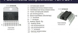
Figure 5 shows the indicator diagram for both stereo channels. It is based on the TA7666R
. Inside the TA7666R IC there are two amplifiers with detectors at the outputs and two lines of comparators, five comparators for each channel.
The gain of each amplifier can be set individually by selecting the resistance of resistors R1 and R2.
With the value indicated in the diagram, the first stage of the LEDs (HL1 and HL6) lights up at input levels of 48 mV, the second stage (HL2, HL7) at 86 mV, the third stage (HL3, HL8) at 152 mV, the fourth stage (HL4, HL9) at 215 mV, fifth (HL5, HL10) at 304 mV. The method of displaying the indication is “bar”, that is, “thermometer column”, in other words, the larger the signal, the longer the line of glowing LEDs. You can always change the sensitivity by selecting the resistances of resistors R1 and R2. Based on this microcircuit, you can make a kind of light-dynamic device, for example, composed of concentric circles of incandescent lamps or LED lamps, for example, used in automotive optics. In this case, additional powerful output stages will be required.
Figure 6 shows a diagram of the output stage for working with automotive LED lamps. An optocoupler with phototransistor U1 is used, its LED is connected instead of the indicator LED. HF1 is an automotive LED lamp. It is powerful and a powerful key field-effect transistor VT1 is used for its switching.
Grinev V.A. Radioconstructor magazine 06-2015
audio Audio equipment subwoofer filter low-frequency mixer
Tone control.
Despite the fact that the regulator looks somewhat unusual, nevertheless, the classic Baxandall tone control circuit is used here. As noted above, due to the low ratings of variable resistances, the capacitor ratings are significantly larger than the “typical” values.
Capacitor C7 (1 μF) determines the lower tone control frequency, and capacitors C8 and C9 have a value of 100 nF and determine the tone control frequency at HF. If desired, the depth of tone control can be increased to ± 10 dB. Due to the IC4 elements, the mutual influence of the low-frequency and high-frequency circuits when controlling timbres is eliminated.
Despite the large dimensions and high cost, the use of polypropylene capacitors is strongly recommended for this part of the circuit.
The tone control noise level is only -113 dB in the middle position of the controls.
Relay RE1 serves to turn off the tone control if it is not needed. In this case, the signal is taken from the output of IC2A and goes directly to the input of IC9B, bypassing the tone control. To avoid clicks during switching, resistor R18 is used. To reduce crosstalk, switching in each channel is carried out by a separate relay. In this case, the relay contact groups can be parallelized, which will reduce the contact resistance and further increase the reliability of this part of the circuit.
High quality preamplifierSchematic diagram, description, printed circuit board of the Solntsev pre-amplifier
Many radio amateurs believe that the sound quality of a household radio complex is almost entirely determined by the parameters of the AF power amplifier and the speaker system. One can hardly agree with this. As practice shows, it is after the appearance of a power amplifier and high-class loudspeakers in the complex that previously unnoticed shortcomings of the remaining components of the sound reproduction path are discovered: pre-amplifier, tone block, pre-amplifier-corrector of the player, etc. Refinement of the path in this case usually begins with the pre-amplifier and regulators volume and timbre. And here it turns out that it is not so easy to formulate specific requirements for them, primarily because the standards for the parameters of these devices largely depend on the chosen structural diagram of the path.
In fact, the preamplifier, volume control and tone control can be connected in different sequences. Most often, the volume control is turned on either at the input of the pre-amplifier (followed by the tone block) or at the input of the power amplifier (i.e., after the tone block). In the first of these options, it is easier to match devices according to signal levels, eliminating overloading of individual stages, but the signal-to-noise ratio is somewhat worse, since the input of the preamplifier in most cases receives a signal attenuated by the volume control. In addition, this option is inconvenient if it is planned to introduce modes such as “Monitor”, independent work with two signal sources, etc.
In the second option, switching is simplified, the requirements for the noise characteristics of the preamplifier can be reduced, but its overload capacity comes to the fore. In this case, it should be at least 20 dB, which is not always feasible.
A compromise option is also possible, in which the volume control is turned on at the input of the power amplifier, and another, additional signal level control is turned on at the input of the pre-amplifier. The purpose of the latter is to reduce the input signal level to the nominal value. This structure seems most suitable for a high-quality sound-reproducing complex.
Much depends on the circuit design of the nodes of the part of the path under consideration. Before choosing them, you need to clearly answer the following questions:
— what (active or passive) should the volume and tone controls be?
— Should there be loudness compensation in the volume control?
— how many bands should the tone control have?
— what should be the limits of tone control?
Active volume controls, which have become widespread in recent years, have many advantages: a large control range, the ability to use available variable resistors of group A, etc. But there are also significant disadvantages: it is difficult to obtain a zero output signal level in them (especially if there is loudness compensation); amplifier stages - the basis of such regulators - introduce distortion into the signal, no matter how small it may be. According to the author, in a high-quality sound reproduction path there should be as few amplification stages as possible, and from this point of view, a passive volume control is preferable.
As for active tone controls, which are also built on the basis of amplifiers, the frequency response in them is formed by changing the depth of the frequency-dependent feedback over a wide range. From the point of view of minimizing nonlinear, intermodulation, phase and dynamic distortions, this operating mode cannot be considered favorable, so it is hardly advisable to use active tone controls in a high-quality complex.
It is advisable to have loudness compensation in the volume control, since without it the sound at low volume levels loses its naturalness. However, the input and output resistances of the thin-compensated regulators known to the author are complex, frequency-dependent and change during regulation over a wide range. For normal operation, such a regulator must be included in the path through decoupling amplifiers, and these, as already noted, are additional sources of signal distortion. Of course, it is possible to provide the possibility of disconnecting the tone-compensation circuits, but this will complicate the switching and will require matching the characteristics of the regulator with the connected and disconnected circuits. In order not to complicate the task, loudness compensation can apparently be abandoned, especially if you consider that distortion of the sound timbre in its absence will only occur at low volume levels, and high-quality phonograms are usually listened to at levels above average.
The answer to the question of the required number of tone control bands is less obvious. Undoubtedly, multi-band regulators - equalizers - have the greatest capabilities. They allow you to adjust the frequency response of sound pressure taking into account the characteristics of the acoustic system, the listening room, and the spectrum of the phonogram. However, equalizer circuits are quite complex; in terms of the level of distortion and noise characteristics, they are significantly inferior to the simplest ones. In addition, as noted in [L], in some cases, high quality sound reproduction is ensured by applying a signal from the source directly to the input of a power amplifier. Based on this, the author considers it advisable to quickly adjust the tone using a conventional passive bridge control of high and low frequencies, and combine the equalizer together with other auxiliary devices (noise suppressor, rumble filter, low and high pass filters, etc.) structurally into a special a block included in the path only in necessary cases (for example, when listening and dubbing phonograms of insufficiently high quality).
Taking into account all of the above, the structure of the considered part of the path appears as follows: an auxiliary regulator (smooth or stepwise), attenuating the signal by 20...30 dB, a pre-amplifier with a horizontal frequency response and minimal possible distortion in the operating frequency range, a passive bridge tone control with small (approximately ±10 dB) control limits and a passive non-thin-compensated volume control. The input and output resistances of the cascades must be selected to ensure their normal joint operation. Since the nominal input voltage of the power amplifier is 0.2 V [L], the total gain of the preamplifier and tone control can be set to 1, i.e., use the first of these devices only to compensate for the signal attenuation of the second. The nominal input voltage of the path in this case will also be equal to 0.2 V, which, on the one hand, is quite sufficient to work with most signal sources, and on the other, allows you to send a signal (while maintaining the level) through the volume control directly to the input of the power amplifier (bypassing the preamp and tone control).
The qualitative indicators of the complex with the chosen structure are determined essentially by the parameters of the preamplifier: its noise, operating frequency range, harmonic and intermodulation distortions, and overload capacity. Based on the technical characteristics of the power amplifier, the following standards for the parameters of the preamplifier were established:
Nominal input voltage. B……0.2
Signal/noise ratio, dB, not less than……. 80
Overload capacity, dB ……… 15…20
Nominal frequency range (based on maximum amplitude signal), Hz, no more than…….20…20,000
Harmonic coefficient in the nominal frequency range, %, no more than ..... 0.05
In addition, one more additional condition was set: the inclusion of a pre-amplifier with a tone control (in the horizontal frequency response position) in the path should not degrade the sound quality during subjective examinations. As it turned out, this requirement turned out to be the most important. A number of devices with very good parameters during such tests introduced distortions, the nature of which is difficult to describe, but their presence was unmistakably determined by the deterioration of “transparency,” “purity,” and naturalness of sound.
After a long search and a series of failures, an amplifier based on the K574UD1A op amp was developed (see Fig. 1), which meets all the requirements. Experiments have shown that the harmonic coefficient of this op-amp strongly depends on the load: it is negligible when its resistance is 100 kOhm or more, it increases to 0.1% at a load of 10 kOhm. From this it was concluded that in order to obtain a sufficiently low level of nonlinear distortion, the op-amp must be “powered up”. For this purpose, a so-called parallel amplifier was chosen. It differs from conventional ones in that there are practically no “step” distortions in it even without OOS. In an amplifier covered by OOS, the harmonic coefficient in the frequency range 20...20,000 Hz does not exceed 0.03% with a load resistance of more than 500 Ohms. Distortions were measured with a S6-5 device. The G3-102 generator was used as a signal source. The harmonic coefficients of the generator itself and the generator with the amplifier were the same. This gives reason to believe that the actual value of the parameter is less than 0.03%. Intermodulation distortion could not be measured due to the lack of necessary equipment.
A schematic diagram of a pre-amplifier with a tone control is shown in Fig. 2. Op-amp DA1 and transistors VT1-VT4 form a linear amplifier that compensates for signal losses in the tone control (R19-R26, C8-C11), an isolation amplifier is assembled on op-amp DA2 and transistors VT5-VT8, the output signal of which is used for recording to a tape recorder. Generally speaking, it is advisable to choose the transmission coefficient of this amplifier close to 1. However, since a more powerful op-amp as a repeater works worse than an amplifier, the transmission coefficient was chosen equal to 13, and to obtain the signal level required for recording, a voltage divider R10R11 was included at the input of the decoupling amplifier . The overall transmission coefficient of the amplifier with a divider is 1.8...1.9.
The bridge tone control has no special features. The frequency response at lower and higher frequencies is adjusted respectively by variable resistors R25 and R20.
Resistors R19, R21 prevent the monotonous rise and fall of the frequency response with increasing frequency, as a result of which it takes on the form shown in Fig. 3 with a solid line. If necessary, using relay K1, the tone control can be excluded from. tract. In this case, the signal is removed from the divider R27R28.
Experimental testing has shown that even without balancing the op-amp and without a capacitor in the “grounded” branch of the OOS divider, the constant component at the output of the amplifiers is small and practically does not reduce the overload capacity. If necessary, coupling capacitors should be turned on at the input of the preliminary amplifier and the output of the decoupling amplifier (they are shown as dashed lines in the diagram).
The parts of the device (with the exception of those that are part of the tone control) are placed on a printed circuit board (in Fig. 4 it is shown for the stereo version) made of foil fiberglass. The tone control elements are mounted on the terminals of dual variable resistors R20 and R25 and connected to it with shielded wires. The board is designed to install permanent resistors MLT-0.25 (R7, R8, R16, R17 can be of type MON-0.5), trimming resistors SP4-1v (R4), capacitors K53-1a, KBZ-18 (SZ, S4 ), KM-66 (S1, S2, S5-S8) and MBM (S9-S11). Variable resistors R20, R25 - dual of any type of group B.
In addition to those indicated in the diagram, transistors KT3107I, KT313B, KT361V, KT361K (VT1, VT4, VT5, VT8) and KT312V, KT315V (others) can be used in amplifiers. In the decoupling amplifier, it is permissible to use op-amps K140UD8B, K140UD8V, and also K544UD2. Relay K1 - RES-60 (passport RS4.569.436) or any other with suitable technical characteristics, but in the latter case you will have to change the design of the printed circuit board. VDI diode - any type with a reverse voltage of more than 50 V. To connect the board to the path, standard MRN14-1 connectors are used (the numbers of their contacts, to which the corresponding amplifier circuits are connected, are indicated on the circuit diagram).
A correctly installed device requires virtually no adjustment. You only need to set the gain of the preamp with and without the tone control connected. In the first case, this is done by tuning resistor R4, in the second - by selecting resistor R27.
For power supply, a bipolar voltage source of ±15 V is required. The current consumed from it depends on the op-amp used and in most cases does not exceed 25...30 mA for both channels. Despite the fact that the noise suppression coefficient in the power supply circuits of the described amplifier is quite high, it is still desirable that the supply voltage ripples do not exceed 10 mV, since otherwise a noticeable background may appear if the installation is unsuccessful. It should also be noted that for normal operation of the tone control, the load resistance must be at least 50 kOhm. When using the device with a power amplifier described in [L], this requirement is met.
A passive volume control (dual variable resistor of group B with a resistance of 100 kOhm) is connected between the output of the device and the input of the power amplifier. To regulate the stereo balance, another dual variable resistor (100 kOhm, group A) is used, turned on by a rheostat (its slider in each channel is connected to the volume control slider, and one of its terminals is connected to the input of the power amplifier).
Moscow Y. SOLNTSEV
More complex preamplifier
Site administration address
Active volume control.
The volume control was also implemented according to the idea of Peter Baxandall, which firstly made it possible to obtain an ultra-low noise level (especially at low volumes), and secondly to obtain a logarithmic control characteristic when using potentiometers with a linear dependence of resistance on the angle of rotation. The maximum gain is +16 dB, with the 0 dB point occurring at the middle position of the potentiometer.
Four amplifiers connected in parallel, as noted above, serve to reduce the noise level by 6 dB. The self-noise level of such a regulator is -101 dB at maximum gain and -109 dB at 0 dB gain. In practice, the volume control is usually set to -20 dB, then the noise level will be -115 dB, which is significantly below the hearing threshold.
So that you can evaluate the quality of each cascade, their own noise levels are given. The resulting noise level of a given preamplifier, as you might guess, will vary somewhat depending on the position of the potentiometers.
The symmetrical output is implemented using a phase inverter on the IC9A op amp and has double the signal amplitude compared to the asymmetrical one. However, this is normal for professional audio equipment.
Design and setup.
Placement of amplifier elements on the board:
Click to enlarge
During assembly, the resistors are soldered first, and then the remaining components. Jumper JP1 is designed to select the optimal ground connection for the vinyl corrector (there are similar jumpers on MC / MD boards). Don't forget to connect them. The connection location is selected experimentally after assembling the structure in the housing.
Photo of the assembled board:
Click to enlarge
This block of settings does not require. Frequency characteristics of the amplifier and tone control:
Click to enlarge
Pre-amplifier with tone block on TDA1524
We assemble a pre-amplifier with a tone block on TDA1524 according to the diagram below, with the exception of small modifications made during testing)
First: adding variable resistors to synchronize the preamplifier with the power amplifier, in our case this is a TDA2050 amplifier.
Second: adding two capacitors to the outputs. After testing, it turned out that they are needed, the sound is more pleasant.
Third: I decided to swap volume, balance, treble and bass. And I made volume, balance, treble, bass from left to right. You don’t have to redo it) I did this purely for myself.
Fourth: to prevent my TDA1524 chip from heating up, I solder it from the bottom of the circuit, and it receives cooling from the case.
Fifth: I etch the circuit in a mirror image for proper installation of the microcircuit.
Sixth: we will power this Pre-amplifier with a TDA1524 tone block from a converted power supply from a PC with a 10-volt power supply.
The scheme itself, without modifications.
Scheme with modifications. 2 capacitors and 2 variable resistors for the outputs.
Great, let's start drawing the board.
Scheme with modifications.
Added capacitors and variable resistors. I almost forgot, I duplicated the output (made it an output for display), from it I will output a signal to the volume indicators, but more on that in a separate article.
Initially, the capacitors are short-circuited, I did this for testing.
I tested it, left one channel with a capacitor connected, left the second without it and checked, with a better capacitor, soldered the second. So don't forget to break the trace under the capacitors.
Also in this circuit, the volume, balance, HV and LF resistors are inverted.
I print on PCB in a mirror manner and place the microcircuit on the side of the tracks.
Accordingly, my volume is the very first on the left side, in order to make a board with volume on the right side, you need to swap the left and right contacts of the variable resistors. If you don't do this, your volume will increase in the opposite direction.
.
We poison, tin, solder.
I recommend that before soldering the parts, check all the tracks with a multimeter for contact.
It often happens that there seems to be a track, but it is not working or has enormous resistance.
The pre-amplifier with tone block on the TDA1524 is ready, we’ll assemble it into a case from under another dead DVD right away with volume indicators.
We will use our preamplifier output for them. We will power the converted unit from the PC. Let's make an entrance and exit. Let's put it in the case.
List of elements:
Resistors: (1% accuracy; metal film; 0.25W) R1,R2,R39,R40 = 100Ohm R3-R6,R41-R44,R78,R79 = 100kOhm R7-R12,R16,R17,R21-R24,R33, R34, R45-R50,R54,R55,R59-R62,R71,R72 = 1kOhm R13,R51 = 470Ohm R14,R15,R52,R53 = 430Ohm R18,R35,R36,R56,R73,R74 = 22kOhm R19,R20, R57,R58 = 20Ohm R25-R28,R63-R66 = 3.3kOhm R29-R32,R67-R70 = 10Ohm R37,R38,R75,R76 = 47Ohm R77 = 120Ohm P1,P2,P3,P4 = 1kOhm, 10%, 1W , stereo potentiometer, linear, for example Vishay Spectrol cermet type 14920F0GJSX13102KA. or, Vishay Spectrol conductive plastic type 148DXG56S102SP.
Capacitors: C1,C2,C10-C14,C26,C27,C35-C39 = 100pF 630V, 1%, polystyrene, axial C3,C4,C28,C29 = 47µF 35V, 20%, non-polar, diameter 8mm, lead spacing 3.5 mm, for example Multicomp p/n NP35V476M8X11.5 C5,C6,C30,C31 = 470pF 630V, 1%, polystyrene, axial C7,C32 = 1µF 250V, 5%, polypropylene, pin spacing 15mm C8,C9,C33,C34 = 100nF 250V, 5%, polypropylene, lead spacing 10mm C15,C16,C40,C41 = 220µF 35V, 20%, non-polar, 13mm diameter, lead spacing 5mm, for example Multicomp p/n NP35V227M13X20 C17-C25,C42-C50 = 100nF 100V, 10%, pin spacing 7.5mm C51 = 470nF 100V, 10%, pin spacing 7.5mm C52,C53 = 100µF 25V, 20%, diameter 6.3mm, pin spacing 2.5mm
Chips: IC1,IC3,IC5-IC10,IC12,IC14-IC18 = NE5532, for example ON Semiconductor type NE5532ANG IC2,IC4,IC11,IC13 = LM4562, for example National Semiconductor type LM4562NA/NOPB
Miscellaneous: K1-K4 = 4-pin connector, 0.1'' (2.54mm) pitch K5,K6,K7 = 2-pin connector, 0.1'' (2.54mm) pitch JP1 = 2-pin jumper, 0.1 pitch '' (2.54mm) K8 = 3-pin screw block, 5mm pitch RE1,RE2 = relay, 12V/960Ohm, 230VAC/3A, DPDT, TE Connectivity/Axicom type V23105-A5003-A201
To be continued…
The article was prepared based on materials from the magazine “Elector” (Germany)
Happy creativity!
Editor-in-Chief of RadioGazeta