Unfortunately, not everyone understands why you need a camera when you have a telephone. And even fewer people understand why a headphone amplifier is needed. We will not just look at why it is needed, but we will also assemble an inexpensive and high-quality portable headphone amplifier. So simple that anyone can do it...
Vol.X© Headphone Amplifier - An attempt to write an article in real time as the project progresses. Comments are welcome!
Follow the progress on Twitter.
As the project progresses, the article will be supplemented with the necessary material. The ultimate goal is to create a complete, easy to replicate , high quality portable headphone amplifier design. The emphasis is on the possibility of implementing an amplifier by a person who does not have deep knowledge of electronics .
If you understand the beauty of pictures floating around the Internet, then you can assemble an amplifier :-).
Why is the amplifier called Vol.X© ? -Don't know. It was simply decided to give a specific name to this project. Sounds more solid. Maybe in time it will come to Vol.X2. Who knows…
Loudness is not the main goal
Many people believe that a headphone amplifier is only needed to listen to music louder. In fact, the value of this gadget is somewhat greater. Any headphones are a complex load for the sound source. This statement is even more true if the headphones are armature, hybrid, iso-/ortho-dynamic or more exotic.
The main problem is usually a lack of output current from the sound source. On the other hand, most modern sources cannot produce a signal of sufficient level to drive high-impedance headphones, such as studio headphones .
The picture is further spoiled by the fact that any speaker has parasitic parameters - inductance and capacitance. They create certain problems for the sound source. The impedance of headphones depends on frequency, and the sound source must be able to cope with this. There are other important aspects for sound, but it won’t go deep into the technical jungle.
To summarize, the main task of a headphone amplifier is to match the signal source to the headphones. At the same time, the original sound quality must be preserved, and the output signal must have greater power than the input.
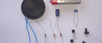
How to choose the right components
The design of standard headphones includes the following components:
Plug with a diameter of 3.5 mm. Its other name is the TRS connector, on the metal surface of which several contacts can be found. Due to them, a linear signal is received from any sound source, be it a computer or a telephone. Depending on the type of headphones, the number of receiving contacts also changes. Stereo headphones have three as a standard, headsets have four, and the most common devices with mono sound are equipped with only two. This is one of the most important points, since the correct selection and connection guarantee the functionality of the gadget at the output.
The design of any headphones itself is simple enough that even a beginner can figure it out. The most important thing when creating a new gadget from several non-working ones is to select really functional components. For this purpose, diagnostics of spare parts is mandatory.
Let's simplify our life
Those who are just discovering electronics and high-quality sound will certainly be pleased with the fact that they will need to assemble an amplifier part. And even then, a printed circuit board and all the other necessary information will be given later, ready for repetition.
The remaining units will be purchased ready-made. This will greatly simplify and reduce the cost of the task without any loss of quality. Self-assembly of such units will significantly complicate the task. And it will not be possible to do without them in the planned design.
In addition, with today's scale of production of various modules, the cost of purchasing parts for such a module is more expensive than the cost of a finished module. A reasonable question arises: why bother?)
How to make a megaphone
1. For the walls of horn D, cut a spruce board to a thickness of 6 mm, cut a piece measuring 102x381 mm from it and divide it into four parts of 89 mm each. Mark narrowings and bevels on both sides on one of these parts (Fig. 3).
2. To correctly and accurately saw the bevels on each of the walls D, make a device from a piece of plywood measuring 203x457 mm. Tilt the saw blade at an angle of 43° and make a bevel on one edge. Prepare four pieces of 25x50 mm dimensions that will serve as stops, and glue a strip of double-sided tape to each of them. Attach two scraps to the support board of the device (photo A) so that they hold the wall blank while filing the first bevel.
Align the bevel marking line on the wall of the horn D with the bevel edge of the supporting board and fix the position of the workpiece with stops made from scraps.
Press the wall blank D with a pusher against the support board of the device and the stops, filing the first bevel.
3. File the first bevel on the walls of horn D at an angle of 43° (photo B). Then glue another pair of stop pieces to the supporting board, orienting the workpiece for filing the second bevel (photo C). After this, make a second bevel on all four walls of the horn.
Without changing the inclination of the saw blade and without moving the longitudinal stop of the machine, rotate the wall blank D 180°, fix its position with the second pair of stops and make a bevel at the opposite end.
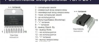
Op amp headphone amplifier
The most convenient option is circuits based on operational amplifiers (op-amps). In this case, the number of elements is reduced to a minimum, and the circuit does not require any adjustment.
The big advantage of operational amplifiers is that all of them, with the exception of specialized ones, are available in DIP8 (Minidip) and SO-8 (aka SOIC) packages.
We will focus on the DIP8 housing. It is larger in size. Therefore, firstly, it is easier to solder, and secondly, it cools better, which is also important for an amplifier. And for those microcircuits that are not produced in DIP8, you can use an adapter from SO-8 to DIP8 .
The purpose of the op-amp pins is standardized and they are interchangeable. Therefore, you can solder the sockets for the microcircuits once and simply insert the microcircuits without the help of a soldering iron. This will not only simplify the replacement of microcircuits but will also protect them from possible overheating during soldering.
Component quality
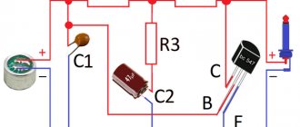
Capacitor C1 must be non-polar. Better polypropylene or film. It is better to use ceramic capacitor C2. The accuracy of capacitors is not so important, but it is better to use an accuracy of at least 5%. Resistors should preferably have an accuracy of no worse than 1%
Good microcircuits are not cheap. For example, for two original OPA2604, which were offered in the original design, you will have to pay about $23.
But it is not at all necessary to immediately purchase the most expensive. To begin with, you can supply something from the assortment of the nearest radio parts store, and gradually replace them with higher quality components. The board will work on any parts.
Prices for operational amplifiers vary widely and more expensive does not always mean better sound. To begin with, you can install something inexpensive and accessible, for example, the beloved NE5532 ($0.3). It is highly desirable that it be made by Phillips.
Subsequently, you can play with replacing the op-amp as much as you want. If we consider op-amps of a higher class, then OPA2134, OPA2132, OPA2406, AD8066, AD823, AD8397… have proven themselves well for sound.
Headphone amplifier circuit
Where this circuit came from and why each specific part was needed was described in detail in the article: Diagram of a headphone amplifier using an op-amp with double the output current .
Making a board
The printed product is key if you want to make a high quality amplifier. Only with it will your product work stably. You can do it at home without any problems if you know the intricacies of LUT technology - this is transferring the design of a standard board using a laser printer and an ordinary iron.
To implement our plans, we will use the Sprint-Layout 6.0 program - the Russian version, it has about 4.6 thousand macros. Its distinctive features:
- all reference data in Russian;
- inscriptions on the board can be made in Cyrillic;
- ideal for Windows 7 operating system;
- The program interface has been changed for novice users;
- You can work from any computer device, it is saved on a flash drive, and leaves no traces on any system.
The image is printed only on glossy paper; you can use various booklets that are distributed in subway passages and shopping malls.
Some radio amateurs use thin glossy photo paper - in this case the print is of higher quality.
It is necessary to print at maximum, then the copy will be of high quality - the entire drawing should be clearly visible. After this, we place it on a fat-free board and iron it with an iron set to the third power position for several minutes. For photo paper, half a minute is enough.
Then we need to carry out etching - for this we use a solution of ferric chloride, which is considered by experts to be the best option. Using acetone, we clean the copper tracks from the remaining paint and begin tinning them. For everything to work out well, it is better to use Rose’s alloy, which was invented by a German chemist - that’s why it is named after him.
The composition of the alloy is 25% tin and lead, and the rest is bismuth - its vapors are extremely toxic, so the whole process must be carried out in a well-ventilated area.
Place several granules of this alloy in a prepared container of water (necessarily with a flat and even bottom) and wait for them to completely melt. Then we place the plate with the pattern down and move it along the bottom with the molten granules. Use a soft sponge to remove stains and excess sagging on the paths.
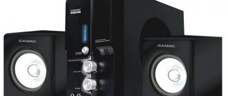
Amplifier power supply
Power directly determines the sound quality of the amplifier. Of course, it is better to use a higher supply voltage, which is also bipolar. For a portable design that will be powered by a single battery, ±5 volts can be considered a good voltage.
This will be enough to drive most headphones, but the battery will handle this power. To obtain the required voltage, we will use a dc-dc converter.
A DC-DC converter is a device capable of converting DC voltage of one value to DC voltage of another value.
Design
All structural elements (except for the power transformer) are placed on one printed circuit board. If you decide to use an external power supply or assemble it in a different way, about 70% of the PCB will remain free.
The layout of the elements is shown in the figure:
Click to enlarge
The figure shows a drawing of the printed circuit board from the parts side:
Click to enlarge
The figure shows a drawing of the bottom side of the printed circuit board:
Click to enlarge
Printed circuit board drawings in the popular SLayout format can be downloaded here.
The main installation feature: on the case on the bottom side of the TPA6120A2 there is a contact pad of approximately 3x4mm. It must be soldered to a pad on the printed circuit board under the chip, which serves as a heat sink.
Photo of the finished structure:
When you turn it on for the first time, you should remove the two fuses at the output of the power supply and make sure it is working. If the output voltages are normal, replace the fuses. The amplifier itself does not need adjustment.
The board can be placed in a case of suitable dimensions, preferably metal, to shield it from external interference.