Nikolay Troshin
Recently, there has been a noticeable increase in interest in power amplifiers based on germanium transistors. There is an opinion that the sound of such amplifiers is softer, reminiscent of “tube sound”. I bring to your attention two simple circuits of low-frequency power amplifiers using germanium transistors, which I tested some time ago.
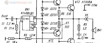
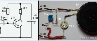
More modern circuit solutions are used here than those used in the 70s, when “germanium” was in use. This made it possible to obtain decent power with good sound quality. The circuit in the figure below is a reworked version of the low-frequency amplifier for “germanium” from my article in Radio magazine No. 8, 1989 (pp. 51-55).
The output power of this amplifier is 30 W with a speaker load impedance of 4 ohms, and approximately 18 W with a load impedance of 8 ohms. The amplifier supply voltage (U supply) is bipolar ±25 V; Operating frequency range 20Hz…20kHz:
A few words about the details:
When assembling an amplifier, it is advisable to use mica capacitors as constant capacitors (in addition to electrolytic ones). For example, the CSR type, such as below in the figure.
MP40A transistors can be replaced with MP21, MP25, MP26 transistors. Transistors GT402G - on GT402V; GT404G – to GT404V; The GT806 output transistors can be assigned any letter indices. I do not recommend using lower-frequency transistors such as P210, P216, P217 in this circuit, since at frequencies above 10 kHz they work rather poorly here (distortion is noticeable), apparently due to a lack of current amplification at high frequencies.
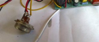
The area of radiators for output transistors must be at least 200 cm2, for pre-terminal transistors - at least 10 cm2. For transistors of the GT402 type, it is convenient to make radiators from a copper (brass) or aluminum plate, 0.5 mm thick, 44x26.5 mm in size.
The plate is cut along the lines, then this workpiece is shaped into a tube, using for this purpose any suitable cylindrical mandrel (for example, a drill). After this, the workpiece (1) is tightly placed on the transistor body (2) and pressed with a spring ring (3), having previously bent the side mounting ears.
The ring is made of steel wire with a diameter of 0.5-1.0 mm. Instead of a ring, you can use a copper wire bandage. Now all that remains is to bend the side ears from below to attach the radiator to the transistor body and bend the cut feathers to the desired angle.
A similar radiator can also be made from a copper tube with a diameter of 8 mm. Cut a piece of 6...7 cm, cut the tube along the entire length on one side. Next, we cut the tube into 4 parts half the length and bend these parts in the form of petals and tightly put them on the transistor.
Since the diameter of the transistor body is about 8.2 mm, due to the slot along the entire length of the tube, it will fit tightly onto the transistor and will be held on its body due to its springy properties. Resistors in the emitters of the output stage are either wirewound with a power of 5 W, or type MLT-2 3 Ohm, 3 pieces in parallel. I do not recommend using imported films - they burn out instantly and imperceptibly, which leads to the failure of several transistors at once.
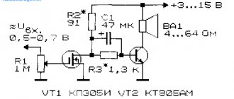
Classic JLH circuit on Germany
I don’t know where the rumor about the complexity of Linsley Hood came from, When literally in two jerks a scheme for the ages took shape.
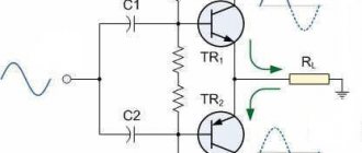
What made me start writing such a circuit was a debugged and tested version of the famous John-Linsley Hood circuit, made on Renesas 2SK1058 and 2SL162 field-effect lateral transistors to improve stability. The circuit is sonorous, broadband, with decent output power, and was designed quickly and without surprises.
I’ve wanted to do something similar on germanium transistors for a long time in the light of new knowledge and experience, and now the opportunity turned up - a topic on Yandex Zen on ULF in Germany. To begin with, the actual output stage was assembled using a pair of powerful germanium triodes in order to understand their behavior at a quiescent current of one ampere. Surprisingly, the transistors behaved completely predictably, did not warm up, and the current remained constant. Then the entire circuit was assembled, including the input stage, OOS circuits and voltage booster.
I used 1T806A as output transistors, as they were the most reliable according to the characteristics in the reference book and reviews from colleagues.
The driver transistor is 1T321V, it has decent gain and pulse current, although the reverse current is also quite large. It immediately became clear that it also needed a radiator - the case became noticeably hot, and the quiescent current flowed. With cooling, the mode was established.
The circuit turned out to be very stable, all that remained was to select a couple of correction capacitors for the lead and lag - according to the best shape of the rectangular pulse and the upward bandwidth. The pulse shape at 50 kHz is shown in the picture.
The full power band turned out to be approximately 300 - 400 kHz; on average, the decline begins somewhere at 1 MHz.
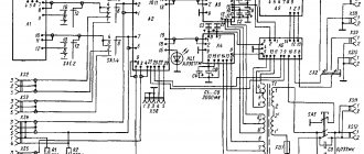
Later, the idea arose to convert the circuit to bipolar power supply with a floating ground to protect the DC speakers in case of an accident. As a result, the scheme took on the following form:
The power transformer secondary midpoint can be connected to the signal midpoint, but it is safer for the speaker not to connect them.
The next modification concerned the replacement of the driver transistor with something more reliable. The P605 was chosen, which has a more powerful case that is not subject to self-heating by the driver’s quiescent current. For better stability, the transistor is still equipped with a small radiator. In this version, the scheme developed as the final one. Although it is not inferior to the unipolar version in any way, except for a few extra details. The choice of circuit here is more a matter of taste; this option is suitable for those who are confused by the presence of a capacitor at the output of the amplifier.
The next solution was to move away from a stabilized power source to a simple rectifier on a standard TN-46 incandescent transformer. It has all four secondary windings connected in series, the output is 25 V alternating voltage, and the rectified supply voltage is 29 - 30 V. The rectifier is simple: a diode bridge on D302 - D305 or Schottky, a capacity of 10,000 μF for 35 - 50 V and a pair of resistors 1 Ohm power 1 W in positive and negative power rails. The latter perform several functions: current control, accident protection, filtering, smoothing of inrush current when charging capacitors.
There is no background in the speakers. The oscilloscope shows residual ripple of a couple of millivolts at the amplifier output.
The sound of this circuit pleased me with its excellent balance, clarity and calmness. Full feeling of tube sound. Measurements of the distortion spectrum confirmed this; the spectrum is indeed beautifully single-ended, falling off quickly and correctly, slowly growing with increasing output power.
- Signal spectrum at 1 kHz 1 Volt at 8 Ohms
- 1.5 Volts into 8 Ohms
- 2.2 Volts into 8 Ohms
- 4.2 Volts at 8 ohms
- 5.3 Volts into 8 Ohms
- 6.0 Volts into 8 Ohms
- 6.6 Volts into 8 Ohms
- Dual tone 11 and 12 kHz
The signal limitation is beautiful, devoid of kinks and emissions; the circuit’s behavior resembles a tube cascade without OOS.
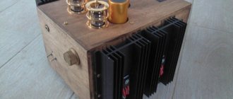
In the prototype, the output transistors were installed on radiators of approximately 500 square cm. Heating with a power supply of 1 ampere was about 60 degrees. For confidently reliable operation of the amplifier, you can limit the supply voltage to 21 - 24 volts, especially in the hot season. With a decrease in output power, the circuit works and sounds clearly from any supply voltage, practically from 2 - 3 volts.
The main parameters of the circuit with a power supply of 30 V and a quiescent current of 0.85 - 1 A
Sensitivity before limiting the output signal: 1 V. Undistorted power into an 8 Ohm load: 5 - 6 W. Input impedance 30 kOhm. Output impedance: 0.77 Ohm. Gain band: 10 Hz - 300 kHz.
share
Tags: JLHJohn Linsley-HoodGermanium
Selection of transistors.
Currently, it is quite problematic to find transistors not only for the 1969 version of the amplifier, but also for the later one - 1996. To help radio enthusiasts, the table below shows the different types of transistors suitable for use in the JLH amplifier. As radio amateurs who have repeated this design note, the type of transistors used significantly affects the sound of the amplifier.
Notes on the table:
- 2N3055 must have a cutoff frequency of at least 4 MHz. (May vary depending on manufacturer)
- 2 TIP3055 are connected in parallel. In this case, 0.1 Ohm resistors should be included in the emitter of each transistor.
- It is advisable to select BD139 with maximum gain to minimize distortion.
The use of more modern transistors labeled “for audio” with a high cutoff frequency of 300 MHz and above causes a large phase shift, which leads to a decrease in the stability of the amplifier and requires the introduction of correction circuits.
In such a simple circuit as the JLH amplifier, the introduction of additional circuits most often leads to an increase in distortion. Therefore, in this case, it is better not to chase fashion trends, but to try to find, if not new, but relatively low-frequency transistors. In this case, you will receive a guaranteed high-quality result.
Of course, there will always be those who like to experiment. Here's what happened when using more modern transistors (for the 1996 version):
- When MJL3281A transistors were installed in the output stage, the excitation of the amplifier was observed in the audio range, that is, it was clearly audible.
- The MJ21194 transistors provided a noticeable improvement in sound quality, but a rather noticeable hum was heard in the low-frequency range, the cause of which could not be identified.
- A significant improvement in sound quality, similar to MJ21194, but without side effects, was achieved by using MJ15003 transistors. These transistors, compared to the 2N3055, gave faster and more collected bass, and the high-frequency range, with the same clarity and detail, became less protruding.
The experimenters were very pleased with the version of the amplifier with MJ15003 transistors, noting that the resistors in their version were tantalum, paper-oil capacitors, and a capacitor with copper plates was installed at the input. With these transistors, as many have noticed, even acoustic systems with metal tweeters lost their harshness in sound (a common problem with such high-frequency speakers).
During the experiments, 2N3055 transistors were changed to MJ15003 without any additional configuration or circuit adjustment. And in all cases, a significant increase in the sound quality of the amplifier was noted.
Finding an affordable replacement for the 2N1711 (TP3) is quite difficult, but the widespread and cheap BD139 is quite suitable here. If you can find 2N1711 or 2N3019, you should give them preference (over BD139) due to their higher gain.
BC212L, BC556, BC557 and 2SA872 can be used as TR4, but low noise devices such as BC559, BC560, and 2SA872 are more preferable.