Almost one year has passed since the idea was born to create an amplifier using these lamps. During this time, I found two enemies - “I don’t want” and “I have no time.” After fierce battles, ours won! As in the previous case with GU29, I chose G807 purely based on appearance. I liked the shape of the balloon. Although, no... I’m lying, not G807, but 6P7S. And you will find out how miraculously 6P7S turned into G807 a little later.
Schematic diagram
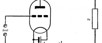
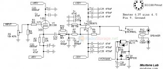
The triode V1a on the left in the diagram is a voltage amplifier loaded onto the phase reflex V1b with a divided (R5, R6) load. A voltage with a depth of 14 dB is supplied to the cathode V1a from the secondary winding of the output transformer through R23.
A high degree of symmetry in the drive of the output lamps VЗ, V4 is ensured by the driver on V2, made according to the differential amplifier circuit with a common cathode load R10.
This solution (compared to the often used two separate amplification stages) provides automatic compensation for the phase splitting inaccuracy of the shared load stage.
The output push-pull stage operates in class AB mode with an initial anode current of 15 mA and a fixed grid bias (adjustable within -25...-62 V with trimmer R4 - see below the power supply diagram in Fig. 2), anode voltage of 700 V and voltage of the second grids 350 V.
Under these conditions, the transconductance of 807 is 6 mA/V, and the optimal anode load (Raa) of 7 kΩ is transformed into a standard load of 8 Ω by Tr1.
Rice. 1. Circuit diagram of a 60-watt tube low-frequency power amplifier (UMZCH) based on analogues of 6N23P and G-807.
Two tube amplifiers (UMZCH)
Tube Amplifiers
The article offers two options for tube audio power amplifiers. A special feature of the presented designs is the galvanic connection between the cascades. The authors attempted to find the optimal combination of simplicity, quality and repeatability of an UMZCH with a single-ended output stage with a power of up to 8 W per channel.
Often, when evaluating a sound reproduction system, the listener consciously or unconsciously focuses on subjective sensations that determine the sound quality. In this case, such characteristics as naturalness, “transparency”, “softness” of sound, “speed” (distinctness) of bass, detail of the reproduced composition, etc. are used. Of course, with a certain degree of convention, these characteristics can be associated with the objective parameters of this system - amplitude -frequency response (AFC), harmonic and intermodulation distortion coefficients, noise and background levels, speaker damping coefficient, etc. Each of the tube UMZCHs offered here, from our point of view, can be considered as a combination of acceptable sound quality, good technical parameters and comparative simplicity circuit solution.
Circuit of a tube amplifier based on a G-807 lamp
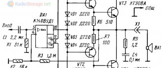
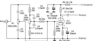
The first amplifier is single-ended, based on a G-807 tube (in Fig. 1 there is a diagram of one of the channels of a stereo amplifier).
It is a modernization of the Profundo amplifier. Here, an additional cathode follower is used, assembled on the triode part of the VL1 (6F1P) combined radio tube. This inclusion makes it possible to coordinate the operation of the input and output stages in order to eliminate the drop in frequency response in the HF region and reduce nonlinear distortions mainly in the LF region that arise in such a circuit when directly connecting the pentode anode and the G-807 control grid. As in the first version of “Profundo”, all stages of the amplifier are covered by a chain of local feedbacks following each other. Local positive feedback (PLF) is necessary not only to exclude the oxide capacitor from the VL1.1 cathode circuit, but also to improve the reproduction of low frequencies (“fast” bass). In its circuit, a voltage divider R7R5 is formed, to which the tetrode screen grid is connected. Capacitor C1 is not required, but can be used to eliminate possible noise when moving the resistor R1 slider. The output stage is assembled using an ultra-linear circuit, which reduces its nonlinear distortion and output impedance.
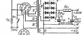
Power supply for lamp UMZCH
The UMZCH I power supply uses a unified transformer TS-180 (from old TVs).
The rectifier is made on semiconductor diodes VD1, VD2 according to a symmetrical voltage doubling circuit. The shallow depth of the general feedback does not provide significant suppression of background from anode voltage pulsations, therefore U-shaped filters with chokes are used in the power supply. The installation of the UMZCH is carried out either according to the method described in the article [1], or (in the absence of instruments) by adjusting the resistor R4 until the maximum audibly undistorted signal is achieved. The quiescent current of the G-807 lamp anode, equal to 70 mA, can be adjusted by selecting resistor R8. The offset on the control grid of the output lamp relative to the cathode is about -20 V. This UMZCH allows the use of an output transformer with a relatively small magnetic circuit without loss of low frequencies. A wideband, highly sensitive (90...100 dB/W/m) dynamic head can be used as BA1.
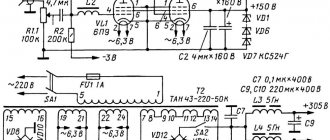
Tube amplifier circuit based on 6С41С triodes
In Fig.
Figure 2 shows a diagram of a single-ended UMZCH II using 6S41C triodes in the output stage (one of the two channels of a stereo amplifier). The first stage is amplified by tetrode VL1 (6E5P), from the anode of which the signal is supplied to the grid of the output lamp VL2 (6S41C). The signal from the middle of the secondary winding of the output transformer T1 through capacitor C2 enters the screen grid VL1, forming a PIC loop. It additionally increases the amplification of the low-frequency signal using circuit LC2 (where L is the inductance of half of the secondary winding of transformer T1), i.e., it performs a corrective function in the region of lower frequencies of the audio range. In this case, the resonant frequency of the circuit can be estimated as fres = 1/(2π√LC2). The OOS is formed by resistor R6 on the screen grid VL1. OOS reduces nonlinear distortion and prevents self-excitation of the amplifier at low frequencies. In the power supply of this amplifier, a rectifier based on semiconductor diodes (using a bridge circuit) is used for the output stage, and for the first stage (on tetrode VL1) a half-wave rectifier is used on diodes VD5, VD6 with capacitors SZ, C5. As a mains transformer in the power supply for both UMZCHs, you can use the TS-180 transformer (or its modifications, for example, TS-180-2) with sufficient power reserve, appropriately connecting the secondary windings to obtain the required alternating voltage (63+63+ 42 V). The amplifier is adjusted by setting the quiescent current for VL2 to 10 = 120 mA by selecting resistor R3. In this case, the bias voltage on the grid of the output lamp relative to the cathode should be about -75 V.
The magnetic cores of the mains and output transformers should be placed mutually perpendicular in the housing to minimize magnetic coupling through the stray field.
The parameters of all UMZCH are given in table. 1. They were measured using an S-107 oscilloscope, a B3-38 millivoltmeter, a GZ-118 generator and a notch filter included in its kit.
In Fig. Figure 3 shows the frequency response of the two proposed amplifiers. For UMZCH I, the frequency response was measured at its rated power Pnom = 5 W (hereinafter - at a frequency f = 1 kHz), for UMZCH II - at a power Pnom = 6 W.
In table 2 shows the parameters of the output transformers for lamps used in UMZCH I and II. To extend the service life of radio tubes, it is advisable to install a switch (toggle switch), through which voltage is supplied to the anodes of the lamps approximately 20 s after their filament is turned on.
Chokes L1 and L2 in Fig. 1 and fig. 2. can be replaced by standardized D31-5-0.14. If they are not available, you can use chokes Dr-1.2-0.16 and the like, however, in UMZCH II the capacitance of capacitors C4, C6 and C7 should be increased to 300 µF. Both UMZCH designs use variable resistors R1 with a type B control curve. The remaining resistors are MLT or imported. Powerful resistor R8 (2.4 kOhm) in the diagram in Fig. 1 - for example, PEV-10 or imported one with higher power. The tolerance for variation in resistor values is ±10%. Trimmer resistor - SP-2-2-0.5, SP-3-9, etc., preferably with an axis stopper. Oxide capacitors - for example, K50-12, K50-17, K50-31 and similar (or imported). The capacitor at the input of the UMZCH can be selected from film (for example, K73-9 series) or paper (K40U-9 series), although its effect on the sound is less noticeable than interstage (in both amplifiers the connection between stages is direct, without capacitors).
When assembling and debugging amplifiers, extreme care and caution should be observed (high voltage). The issues of eliminating the background of alternating current are well presented in [2, Ch. 3) and [3].
To design the amplifier, you can use the recommendations set out, for example, in [2, Ch. 4]. Let us add that the UMZCH chassis can be made of aluminum or steel with a thickness of 1.5 and 0.5...0.8 mm, respectively. Input connectors are RCA (“tulips”), output terminals are threaded. It is advisable to place the trimmer resistor in the cathode circuit as close as possible to the input lamp. Its body is connected to a common wire or shielded. The wires of the incandescent circuits are twisted together. The psychoacoustic characteristics of each of the described UMZCHs have their own characteristics. In our opinion, the first UMZCH is characterized by detail and transparency of the sound palette, the second - a combination of the softness of the bass register with the clarity of high-frequency sound components. A common characteristic feature of both designs is the “warmth” of the sound, as is commonly said about sound with tube amplifiers. We wish you success!
S. AKHMATOV, D. SANNIKOV, Ulyanovsk
LITERATURE 1. Akhmatov S., Sannikov D. “Profundo” - tube audio frequency amplifier. - Radio, 2012, No. 5, p. 16, 17. 2. Adamenko M.V. Secrets of low-frequency tube amplifiers. - M: NT Press. 2007. 3. Simulkin S. Secrets of High-End tube technology. - Radiohobby, 1999. No. 4, pp. 49-52.
Source: Radio Magazine No. 5 (May) 2016 p.17
UMZCH tube amplifiers
Details and design
The design of the windings of the latter is shown in Fig. 3. It is made on a W-shaped magnetic core SM-102b (area about 36 cm2).
Rice. 3. Design of windings Tr1 for a lamp UMZCH circuit.
Each of the series-connected sections of the primary winding n6-n1З consists of 262 turns of PEV-0.3”, and each of the parallel-connected sections of the secondary winding pi-n5 consists of 75 turns of PEL-0.5.
The network transformer is also made on the magnetic core SM-102b:
- primary winding n1 contains 390 turns of PEV-0.7;
- secondary windings n2 - 450 PEL-0.35, nZ - 490 PEV-0.35, n4 and n6 - 11 PEL-1.2, n5 - 18 PEL-0.5, n7 - 100 PEL-0.2.
Three amplifier circuit options
Making an amplifier is not easy. Making a good amplifier is even more difficult. But of the three proposed schemes, you will probably like one. When moving to a higher level, you will not have to change either the chassis, transformers, or lamps.
Freedom of choice is not only a philosophical concept, but also a powerful incentive for creativity. Especially in our business, when desires do not always coincide with possibilities. Indeed, sometimes you have to abandon a very tempting project due to the lack of necessary lamps or transformers. And it happens that you don’t like some little thing in the circuit - you want triodes at the output, but they offer pentodes, or vice versa. Now, if only everything was the same, but with mother-of-pearl buttons...
Freedom of choice is not only a philosophical concept, but also a powerful incentive for creativity. Especially in our business, when desires do not always coincide with possibilities. Indeed, sometimes you have to abandon a very tempting project due to the lack of necessary lamps or transformers. And it happens that you don’t like some little thing in the circuit - you want triodes at the output, but they offer pentodes, or vice versa. Now, if only everything was the same, but with mother-of-pearl buttons...
We decided to develop a transformer circuit so that, having power and output transformers plus a certain set of lamps, you could easily convert one option to another. Here there is limitless scope for implementing your own sound concept, since you can always settle on the one you like best. Since it is impossible to embrace the immensity, we will present only three schemes based on the principle of reasonable compromise.
In all three options, a high-frequency pentode with a short characteristic 6Zh8 in triode connection is installed at the input. It is housed in a shielded metal housing and is very linear at low signal levels. As a driver/bass reflex, the 6N8C octal double triode turned out to be the best - with a low gain, good linearity and decent anode current.
As output tubes, we preferred the G807 beam tetrode or its 6P7S octal version. Thanks to its design and very deep vacuum, in our opinion, it significantly surpasses such well-known lamps as 6P3S, 6P3SE, 5881, 6L6, KT66, KT88, 6550, EL34 in sound transparency.
If you adhere to the recommendations listed below, then success in building an amplifier will be guaranteed. For the sake of brevity, we present them briefly.
1. Amplifiers are made in the form of monoblocks, and each circuit is given for one of them.
2. The amplifier housing (chassis), as well as the fastening elements of the transformers, are made of non-magnetic material (copper, brass, aluminum).
3. Transformer cores, both power and output, are assembled from W and P plates with a thickness of 0.35 - 0.55 mm.
4. Power transformers must have low current x.x. and operate at reduced induction.
5. Output transformers must operate in the linear portion of the characteristic, have good phase and frequency properties, both at low and high frequencies, while the number of winding sections should be as small as possible.
6. It is advisable to use transition capacitors made of foil, paper-oil or impregnated with ceresin, from domestic ones - KBF, from imported ones - Jensen, in extreme cases, polypropylene, domestic K78-2, imported Multicap, Relcap, etc.
7. The quality of resistors should not be neglected. Avoid metal oxide MLTs and the like. The best results in these circuits were shown by carbon types C1-4, BC, BLP or their imported analogues; it is also possible to use tantalum resistors.
8. Rectifier diodes must be Ultra-Fast or FRED (Fast Recovery Diodes).
9. High-voltage electrolytic capacitors in the power supply are domestic, preferably K50-27, imported - Black Gate Rubycon, Elna Cerafine. It is desirable to shunt high-voltage electrolytes with metal-paper type K42, made in non-magnetic cases with a capacity of at least 4 μF, and mica type KSO with a capacity of 0.01 μF.
Low voltage electrolytes in the cathode circuits greatly affect the sound. Among domestic ones, we recommend K50-24, but better imported ones are Black Gate Rubycon and Elna Cerafine. Please note that the last two need time to “play out”, and they will show all their abilities after a two to three hour warm-up. Cathode capacitors must be shunted with metal-paper type K42 with a capacity of at least 1 μF and mica KSO with a capacity of 0.01 μF.
10. Lamps should be used octal, as old as possible, manufactured in 1950 - 1975.
11. For domestic installation wires, it is better to look for MGTF 0.35 mm2, MPO 0.75 - 1.5 mm2 (they are available on radio markets and are inexpensive). Imported - Kimber, XLO, etc. All connections longer than 5 cm must be made with twisted pairs.
12. Installation should be done in a three-dimensional hinged manner, with maximum use of the leads of the parts themselves.
13. Do not skimp on input and output connectors, fuse holders, switches and power sockets - their quality not only affects the reliability of the products, but also affects the sound.
14. The ground is connected to the housing only at one point - near the input lamp.
15. All soldering is performed with POS-61 or imported solder of good quality. The solder should be drop-shaped and shiny. If the soldering has a matte structure, this indicates overheating and crystallization of the solder or its low quality, which will immediately affect the sound. Select the desired temperature of the soldering iron tip - regulator diagrams have been published more than once in Radio. It is best to purchase a soldering station with a regulator and temperature stabilizer. We strongly recommend premium quality pine rosin as a flux.
So, let's start looking at the schemes. Let's start with fig. 1.
| Table for diagram 1. | |||
| Resistance | |||
| R1 | 47k | Alps | |
| R2 | 470k | 1/4w | carbon |
| R3 | 15.5k | 2w | carbon |
| R4, R11 | 300 | 1/4w | carbon |
| R5 | 10k | 2w | carbon |
| R6, R10 | 160k | 1/4w | carbon |
| R7, R8 | 20k | 4w | carbon |
| R12, R14 | 100k | 1/4w | carbon |
| R13 | 10k | 1w | SP4-1 |
| R15, R16 | 1k | 1/4w | carbon |
| R17, R18 | 100 | 1/4w | carbon |
| R19 | 50 | 4w | carbon |
| R20 | 100k | 2w | carbon |
| R21 | 3k | 2w | carbon |
| Capacitors | |||
| C1, C9 | 0,01 | KSO, SGM (mica) | |
| C2, C10 | 1 µF | K42 (paper) | |
| C3, C11 | 4700 uF x 16 V | K50-24, Black Gate, Elna | |
| C4, C8 | 1 µF | MBM, K42 | |
| C5 | 100 µF x 450 V | K50-27, Black Gate, Elna | |
| C6,C12,C13,C14 | 1 µF x 450 V | K78-2, KBF, Jensen | |
| C7, C15, C16 | 220 uF x 450 V | K50-27, Black Gate, Elna | |
| C17 | 4 µF x 450 V | MBM, K42-11 (paper) | |
| C18, C19 | 100 µF x 100 V | K50-27 | |
| C20 | 0,01 | KSO, SGM (mica) | |
| Semiconductors | |||
| VD1 - VD4 | MUR 4100 | Motorola | |
| VD5 - VD8 | MUR 1100 | Motorola | |
| VD9, VD10 | KS 518A | zener diode | |
| Lamps | |||
| V1 | 6Zh8 | ||
| V2 | 6N8 | ||
| V3, V4 | G807, 6P7 | ||
The input stage is made using a 6Zh8 tube in triode connection without local feedback. The non-self-balancing driver (aka bass reflex) is built on a 6N8S double triode without feedback. The G807 output tubes are triode-based, their bias is fixed. Setting up the amplifier is simple: you just need to use substring resistor R13 to achieve the same signal amplitude with a frequency of 1000 Hz on the first and second anode of the 6N8S lamp, and also set the quiescent current of the G807 output lamps within 40 - 50 mA by selecting one of the zener bias diodes in the power supply. Attention! It is unacceptable to turn on the anode voltage until you have verified that there is a negative bias on the grids of the output lamps.
Scheme No. 2, Fig. 2.
| Table for diagram 2. | |||
| Resistance | |||
| R1 | 47k | Alps | |
| R2 | 470k | 1/4w | carbon |
| R3 | 15.5k | 2w | carbon |
| R4 | 300 | 1/4w | carbon |
| R5 | 10k | 2w | carbon |
| R6 | 160k | 1/4w | carbon |
| R7, R8 | 20k | 4w | carbon |
| R9 | 5k | 4w | is selected |
| R10, R11 | 100k | 1/4w | carbon |
| R12, R13 | 1k | 1/4w | carbon |
| R14, R15 | 100 | 1/4w | carbon |
| R16 | 100k | 2w | carbon |
| R17 | 50 | 4w | carbon |
| R18, R19 | 33k | 1/2 w | |
| R20 | 11k | 2w | |
| R21 | 1k | 2w | |
| Capacitors | |||
| C1 | 0,01 | KSO, SGM (mica) | |
| C2 | 1 µF | K42 (paper) | |
| C3 | 4700 uF x 16 V | K50-24, Black Gate, Elna | |
| C4,C8 | 1 µF | MBM, K42 | |
| C5 | 100 µF x 450 V | K50-27, Black Gate, Elna | |
| C6,C9,C10 | 1 µF x 450 V | K78-2, KBF, Jensen | |
| C7,C11,C12 | 220 uF x 450 V | K50-27, Black Gate, Elna | |
| C13 | 4 µF x 450 V | MBM, K42-11 (paper) | |
| C14, C15 | 470 uF x 100 V | K50-27 | |
| C16 | 100 µF x 160 V | K50-27 | |
| C17 | 0,01 | KSO, SGM (mica) | |
| C18 | 1 µF x 160 V | K42 (paper) | |
| C19 | 220 uF x 160 V | K50-27 | |
| Semiconductors | |||
| VD1 - VD4 | MUR 4100 | Motorola | |
| VD5, VD6 | MUR 1100 | Motorola | |
| VD7, VD8 | KS 518A | zener diode | |
| Lamps: see Diagram 1 | |||
The input stage is similar to the previous one. The bass reflex driver is made on a 6N8S lamp using a differential circuit with a “long tail”. More precise equality of the amplitudes of the positive and negative half-waves is achieved by using a negative voltage source of -100 V. Even better symmetry can be achieved if you include in the 6N8 cathode circuit a current source on an RF pentode with a short 6Zh4 characteristic in a triode connection (shown with a dotted line instead of a cathode resistor). The G807 output tubes here also operate in triode connection. The amplifier is configured by selecting the cathode resistor of the 6N8S lamp so that the voltage at its anodes is equal to approximately half the supply voltage. In the case of using a 6Zh4 lamp with a 100 Ohm trimming resistor, the same operation is performed. Setting the quiescent current of the G807 output lamps - as in circuit No. 1.
Scheme No. 3, Fig. 3 .
| Table for diagram 3. | |||
| Resistance | |||
| R1 | 47k | Alps | |
| R2 | 470k | 1/4w | carbon |
| R3 | 15.5k | 2w | carbon |
| R4 | 300 | 1/4w | carbon |
| R5 | 10k | 2w | carbon |
| R6 | 160k | 1/4w | carbon |
| R7, R8 | 40k | 4w | carbon |
| R9 | 10k | 4w | is selected |
| R10, R11 | 100k | 2w | carbon |
| R12, R13 | 1k | 1/4w | carbon |
| R14 | 47 | 1/4w | carbon |
| R15 | 120 | 1/4w | is selected |
| R16 | 3k3 | 2w | carbon |
| Capacitors | |||
| C1 | 0,01 | KSO, SGM (mica) | |
| C2 | 1 µF | K42 (paper) | |
| C3 | 4700 uF x 16 V | K50-24, Black Gate, Elna | |
| C4,C8 | 1 µF | MBM, K42 | |
| C5 | 100 µF x 450 V | K50-27, Black Gate, Elna | |
| C6,C9,C10 | 1 µF x 450 V | K78-2, KBF, Jensen | |
| C11 | 240 pF | is selected | |
| C12 | 0.1 µF x 630 V | MBM, K42-11 (paper) | |
| Lamps | |||
| V6, V7 | SG4S | gas zener diode | |
The input stage and driver-phase inverter are the same as in circuit No. 2. The G807 output tubes are switched on by tetrodes. The supply voltage of their second grids is stabilized by two SG4S gas zener diodes connected in series. An OOS is introduced from the output winding of the transformer into the grid of the second triode of the 6N8S lamp. In parallel with feedback resistor R15, phase correction capacitor C11 (preferably mica type KSO) is switched on. The gain in this case becomes equal to KU = R15/R14 + 1. By changing the value of resistor R15, i.e. By changing the feedback depth, the required output impedance (i.e. load damping) and amplifier sensitivity are set. The value of C11 depends on many factors, so it is easier to select when tuning.
Now a few words about feedback. It is almost impossible to build such a circuit without an OS, since the internal resistance of the tetrode changes tens of times over the signal period, in contrast to the triode, in which the internal resistance remains almost constant. Therefore, feedback in a tetrode amplifier is simply vital, but it should not be abused. Its depth should be such that the bass drivers in your speakers do not hum in the lower middle, and no more.
The power source here is exactly the same as in circuit No. 2.
From the editor
All three schemes have different sounds, each of which has its own advantages. We won’t describe it - a lot depends on both the listening conditions and the tract itself. It seemed to us that the pentode connection gives better results with vinyl, and the triodes soften the digital sound. The apotheosis of the described project could be the use of directly heated 6S4C (even better - 2S4S) at the output, but you will have to tinker with the filament power supply in order to achieve minimal background noise at the output. If you can’t make the chassis yourself or wind the transformers, contact companies that sell WHALES. Their advertisements periodically appear on the pages of Practice.
Practice AV #1/2002
share
Tags: transformer circuit
Setting up
The adjustment comes down to setting the power supply trimmer P4 (Fig. 2) and resistor P1 (Fig. 1) to such a bias voltage on the grids VЗ, V4, at which the anode currents will be equal to 15 mA. They must be measured by the voltage drop (it should be equal to 15 mV) across the cathode resistors R19 and R20.
Then resistor P1 should be used to minimize the harmonic distortion or simply achieve the best sound by ear, compensating for possible slight differences in the characteristics of V3 and V4.
Sukhov N. E. - The best designs of ULF and subwoofers with your own hands.
G807 - two-stroke LUMZCH, increased power
The article discusses several options for constructing highly efficient tube UMZCHs using standard transformers and the common powerful G807 generator tetrode. This is a relatively good vacuum tube that allows you to build a powerful linear amplifier of an extremely high class without any difficulty. It should be noted that difficulties in designing a relatively high-voltage amplifier are quite possible, but they are surmountable and completely classic. The general motive for the publication is as follows. In pursuit of powerful foreign EL-34 lamps, some TV viewers tend to lose their minds and human appearance. Trust the old man. In the Soviet arsenal there are quite comparable specimens - for example, G807. The unit power of the tetrode is quite high - 27 W of dissipation along the anode, the lamp has an overload capacity, there is no self-heating and it can be loaded a little more. Not very good for G807 - low maximum permissible voltage on the second grid. An increase in distortion during overvoltages limits the level of supply voltages to the electrodes in an ultralinear connection. In addition, the upper location of the anode cap creates some practical utilitarian inconveniences - this is indisputable. But the cost of domestic electronic tubes is quite acceptable - 100-150 rubles per cylinder. But for the bourgeois glass indicated above, the speculative price is 30-40 times higher. And this is obvious disgusting, the speculators have gone crazy and are making money on the horses. That is why I boldly say, use high-quality domestic tubes and carefully configure the amplifiers to minimize distortion. The result will be simply stunning. All my work is anti-marketing for bourgeois glass .
As a matching output node in a tube amplifier, I prefer to use a pair of differentially connected transformers. It is less preferable to use homemade output trances of a traditional design. It is even less preferable to use bourgeois transformers. There is nothing special about them, and the price tag is hefty. And since the “civilized” English-speaking foreign countries are traditionally hostile to Russia, I am happy to be ready, at any moment in my life, to fully reciprocate. Ordinary people, as a rule, have nothing to do with this, they are stupid and lazy Eloi, but kings and oligarchs should “sleep off” on increased nutrition, ahead of schedule and all the way. We are categorically against supporting any business of enemy origin with rubles.
For the first two circuits on the G807, the skeleton of old man Williamson’s product was used, where we have an amplification stage with direct coupling and a phase reflex with load sharing. The specified output tube does not require a huge drive voltage, so the use of a shared load is justified. Conveniences include the absence of a strict need to select the parameters of dual triodes according to symmetry conditions. However, if you still happen to measure the first lamp, preference should be given to the specimen with a higher current of the second triode, or the lamp should be soldered to the base backwards. A standard (sound) transformer, often found in nature, can be used as the main matching unit of the first circuit. For a circuit with a single transformer, it is better to use the output from the TU50 installation, which will completely pull out the dual lamps of the output stage. The use of dual tubes will allow you to extract up to 60 watts of sound power of extremely high quality from the amplifier into an 8 ohm load. The advantages of this solution are quite obvious - cheap standard (non-audio) outputs and excellent amplifier quality. But the alternating current background will have to be thoroughly defeated by using stabilizers and bias in the filaments. This will not be difficult, since the G807 tetrodes have a fairly low filament current.
Since a typical audio output does not have taps for ultralinear switching, it is possible to fully implement separate power supply for the anode and screen grids by providing this in the power supply. There is no need to stand on ceremony with voltage levels, since the G807 handles elevated levels quite well both at the anode (+550) and at the grid (+350). But the cathode current should be slightly reduced to AB mode. The lack of a sufficient number of windings on the output transformer precludes the simultaneous use of cathode and grid feedback. This does not improve linearity. You can use the OS through traditional cathode windings, although they are not shown in the diagram with a simple transformer. The huge power reserve in the transformers will ensure the highest sound quality with this amplifier for almost any acoustic system in the range of 5-50 tube watts.
The second circuit is also implemented on the basis of the Williamson structure, but the standard output transformers are not audio at all and are connected differentially, according to Komarov’s recommendations. This approach is quite suitable for standard TPP and TN transformers. The power taken from the amplifier into an 8 ohm load is close to 80-90 watts with a harmonic distortion of no more than 1.5%. Here you need to provide a relatively powerful power source that maintains a more or less stable anode voltage. This stress is reduced due to the ultra-linear inclusion of the grids. Without a reserve in the anode power supply, it will not be possible to squeeze out the declared output power when the anode voltage is reduced to +450 volts even from dual G807s, you need to clearly imagine this. For those interested, I will email you the standard ratings of transformers suitable for differential switching.
Cathode feedback, implemented through additional windings of output transformers, has a very beneficial effect on the characteristics of the amplifier. When the equivalent voltages of a group of windings in the feedback circuit of one cathode are up to 25-30 volts, no tricks arise during tuning. It is quite simple to phase such windings, even if there are errors in the circuit, using an ordinary oscilloscope. But increasing the voltage of the OS windings to 80 volts unjustifiably reduces the overall gain without a noticeable effect in increasing linearity. In addition, self-excitation is possible due to the low quality of mounted installation and the long length of the tails. All conductors of the anode-grid group and cathode OS should be made in the form of a twisted pair, one of the wires of which is grounded to the common wire of the DC bus.
I will show another version of the evolution of the circuit with a dual differential output stage later. There are some changes, sensitivity has been reduced and the dynamic range has been expanded at the same high output power values. The same 6n9s light bulb was used in the FIX bass reflex circuit. The voltages are selected higher, and the currents should not be driven more than 1 -1.5 mA. To reduce distortion, triodes should be selected according to symmetry conditions with an accuracy of 2-3% in slope. For current symmetry, the selection condition will be less stringent when using 6N8S in light mode. Private measuring experience has shown in practice that the quality of symmetry for 6N8S can be an order of magnitude worse than 6N9S, although much apparently depends on specific batches of lamps. It should be noted that with some external complexity of the differential connection of transformers, the shown power cascade circuits have undeniable advantages. They provide extreme tube amplifier output with large tubes and consistently good sound quality. The guaranteed bandwidth of an amplifier built on standard transformers is rarely worse than 20 Hz-20 kHz with unevenness at a level of 3 dB. But there is a pitfall in differential inclusion that you should be aware of. Selection of output transformers into differential pairs is required, and this selection must be performed with great care.
Below are three diagrams in which the difference lies only in the method of connecting the output windings of the matching transformers. The transformers are the same, with a rated power of 86 W. Initially, all output windings are connected in parallel. In this case, the load capacity of the transformer is higher. But this is redundant. Since it is difficult to extract more than 40 W of useful power from a pair of G807 lamps. Therefore, it makes sense to place the windings of the uppermost layers in another connection.
In the following circuit, a pair of output windings are transferred to the anode circuits. The wire in the winding is of small diameter, and the maximum resulting current of the three windings is about 2.1 amperes. Therefore, the power of one output is written on the diagram as 59W. But this is too much. A pair of transformers will provide about 120 watts. And this is too much for a pair of G807s. Therefore, take another winding from each trans into the anode circuits, for better flux linkage with the output windings. In this case, the equivalent reduced resistance of the matching transformer will be slightly increased, since the turns in the anode have gone up. Consequently, in terms of performance characteristics, the load line with the operating point will be slightly higher, and the operating parameters will also be slightly different.
In the last circuit, only a pair of windings are left on each output transformer. Load current within the limit of 1.4 amperes. And therefore, the maximum value of the power taken does not exceed 40+40 W. But there will be plenty of this too. If the selection is halved, then the induction in the cores can also be reduced by approximately half.
G807 tetrodes are quite nice in appearance. There is a supply. That's why they are sold here, but only in matched pairs. And a tube amplifier with such bulbs can be bought here at a price of 40K and above. To do this, just contact me by mail, discuss the price of the product and delivery conditions, pickup is possible. After this, the person interested should call the phone number indicated on the website to discuss the details, and only then make an advance payment of 20% of the agreed amount to my Sberbank account. Having received the transfer, I send a notification and within two weeks I will call you back with confirmation of proper packaging of the product and readiness for shipment, and I will send photographs of this particular unit, opened and packaged, by email. For shipment, the buyer is required to transfer the remaining amount, after receiving which I carry out the shipment and email a copy of the receipt. If the buyer's circumstances have changed within the specified period of time, then the purchase can be refused. The listed deposit is not refundable. The amplifier has a 12 month warranty from the date of delivery. The warranty does not apply to glass sent by post or transported by a transport company. Sincere wishes to everyone for good health and success.
Evgeny Bortnik, Krasnoyarsk, Russia, November 2016