Save and read later -
- Part 1. Device, properties and parameters
- Part 2. Basic characteristics of capacitors
Capacitors are fundamental passive electronic components for both analog and digital circuits. In them, they find a wide range of applications, including energy storage, blocking direct current while passing the alternating component of the signal, filtering signals, and so on. The scope of application of capacitors depends on their characteristics: capacitance, rated voltage, physical dimensions and installation method, equivalent series resistance, dielectric loss tangent. Also, when choosing it, parameters such as the temperature coefficient of the container, the presence of a microphone effect, and time between failures should be taken into account. Depending on its location in the electrical circuit, a capacitor can perform various functions, namely:
- Separate the DC component from the variable in the input signal, performing the function of a high-pass filter
- Shunt (divert) the variable component of the signal, thus acting as a low-pass filter (low frequencies pass through, high frequencies are eliminated)
- Store energy and act as a source of voltage.
Let's look at each capacitor function separately.
Using a capacitor as a separating element
A capacitor connected according to the circuit shown in Fig. 1 is called coupling capacitor.
Rice.
1. High pass filter. The signal source (alternating voltage source) through a capacitor operates on the load resistance Rн . The circuit shown in Fig. 1 is a first order high pass filter. In English literature this sounds like a high pass filter, and a capacitor that is connected in this way is called a coupling capacitor. Since the reactance of a capacitor is determined by the formula
it is obvious that the lower the frequency, the greater the resistance will be. At a frequency of 0 Hz, the resistance will be infinitely large. If we consider the transient process, when a constant voltage (f = 0 Hz) is applied to a discharged capacitor, then first a large current will flow, the magnitude of which will be determined by the equivalent series resistance
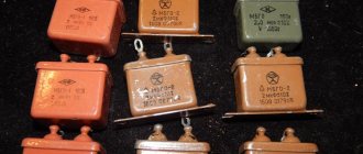
The capacitor will quickly charge, and after that the current will sharply decrease to almost 0 A. The magnitude of the constant leakage microcurrent that will pass through the capacitor depends on the properties of the dielectric in the capacitor, that is, on the value of the dielectric loss tangent, which was discussed in the previous part of the article. Film and foil capacitors have the best characteristics. The higher their rated voltage, the better the insulation, and therefore the less leakage. That is why in the signal circuits of high-end audio equipment, film or foil capacitors are used, often exceeding the nominal value of the actual maximum possible operating voltage by hundreds and even thousands of times.
Cutoff frequency (fc), that is, the frequency at which the signal is attenuated in
(equivalent to a decrease of 3 dB on a logarithmic scale),
(2)
From expression (2) it follows that the higher the cutoff frequency, the smaller the capacitance of the capacitor should be. For good signal passage through the capacitor, its reactance Xc must be 20 - 50 times or more less than the load resistance Rн, then a very small part of the input signal is lost on it. For clarity, let’s calculate the capacitance of the separating capacitor, which will be at the input of the amplifier stage with the following parameters:
Rн = 100 kOhm – cascade input resistance
Fc = 20 Hz – lower audible limit at level -3 dB
Let Xc = 1/50 Rн = 2000 Ohm, then
Since such a rating is not in the E24 rating line, and the value of 4 μF is in the range of 3.9 and 4.3 μF, in practice you can choose any of them. If you select 3.9 μF, then the cutoff frequency will shift up, and if 4.3 μF, then vice versa, down.
Coupling capacitors are also used to isolate high-frequency components from a signal and are often used in audio signal processing.
↑ Installation and details of the improved power supply circuit
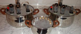
The printed circuit board of the power supply is designed to install four oxide capacitors of 4700 μF for an operating voltage of 35 V in each arm (Fig. 9).
You can first install one capacitor at a time, and then add the missing ones, and thereby finally clarify for yourself the question of their influence on the sound of the amplifier. Fragment excluded. The full version is available to patrons and full members of the community.
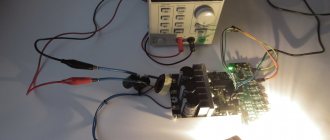
First, small-sized parts are installed on the printed circuit board: film capacitors, diodes, electrolytic capacitors of a bipolar power supply. Then the terminal blocks and electrolytic capacitors of the smoothing filter are installed. After soldering, it is advisable to further strengthen the latter on the printed circuit board using hot-melt adhesive. An electric glue gun is required (Fig. 10), designed for gluing together products made of plastic, metal, ceramics and other materials. It is used for fastening large parts (oxide capacitors, transformers, chokes, etc.) on printed circuit boards, fixing connectors and many other purposes.
The consumable material for gluing is silicone hot melt adhesive, which is produced in the form of cylindrical rods with a diameter of 11 mm in various colors. The rod is installed into the gun through a hole in the rear of the plastic housing. After plugging in and warming up, the instrument is ready for use. The narrow tip of the gun allows you to operate in hard-to-reach places, and the trigger-dispenser ensures a controlled supply of glue through the heating element. After squeezing the molten silicone mass onto the surface to be glued, you should press the parts until the hot-melt adhesive sets.
Rice. 10. The glue gun is easy to use, reliable and durable
Power supply details:
Show/Hide text
DA1 – Stabilizer 7815 (15V; 1.0A), TO-220 – 1 pc., DA2 – Stabilizer 7915 (-15V; 1A), TO-220 – 1 pc., U-shaped radiator FK301, aluminum, 13.3 ×19.1×12.7mm, for TO-220 type cases – 2 pcs., VD1…VD4 — Schottky diode 80SQ045-IR (45V/8A) – 4 pcs., R1 — Res.-0.25-470 Ohm (yellow, purple, brown, golden) - 1 pc., C1 - Cond.0.1/1000V K78-2 - 1 pc., C2, C15...C18 - Cond.0.1µ/63V J K73-17 - 5 pcs., C3...C6 - Cond.0.01/630V K73-17 - 4 pcs., C7...C14 - Cond.4700/35V 1840 +105°C - 8 pcs., C19, C20 - Cond.100/25V 0809 105°C – 2 pcs., Terminal block 3K pitch 5 mm TV-03ВС per board – 3 pcs., FU1 – Fuse holder for instrument block 5x20 mm, FH-02, — 1 pc., Prev. 1A (d=5;L=20) glass. – 1 pc., XP1 — pc. “Network” CS-001 prib./latch – 1 pc., Contact. type “O”, TRI-1.25-2.5-M5, insulated - 2 pcs., XT1 - Instrument terminal block - 1 pc., SA1 - Power switch 250V, 6A - 1 pc.
Using a capacitor as a decoupler
Rice.
2. Low pass filter. The signal source (alternating voltage) operates on load resistance Rн. In this circuit, the capacitor serves as a decoupling element. The decoupling capacitors pass the constant voltage part of the signal, while the variable part is shunted to ground. This is due to the high reactance (in an ideal model it tends to infinity) of the capacitors for constant voltage signals (f=0), which is significantly reduced for alternating voltage signals (f>0). Thus, the output produces a constant voltage without interference (Fig. 3)
The decoupling capacitor is used as a low-pass filter: the noise signal is suppressed. To filter low-frequency noise, capacitors with a capacitance in the range from 1 to 100 μF are usually selected.
Let's look at the use of capacitors using a clear example - the circuit of the simplest amplification stage shown in Fig. 4.
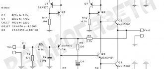
Rice. 4. Circuit of a single-stage amplifier assembled according to a common-emitter circuit using a reverse conduction transistor (npn).
In Fig. 4, the DC component of the input signal can be created by power supplies or preliminary amplifier stages located at the input of this amplifier. In audio signal circuits, the DC component of the input signal affects the quality of the output signal by introducing noise and distortion. In the circuit shown in Fig. 4, coupling capacitor C1 is placed at the amplifier input in front of the Vs signal source. To prevent the appearance of a constant output signal, a decoupling capacitor C2 is connected to the collector of the transistor in series before the load RL.
Blocking capacitors are necessary in amplifier circuits. They are used to avoid applying the power (+Vcc in Fig. 4) of transistor VT1 to audio signals. In most cases, this is achieved by turning on a capacitor at the input of the amplifier, in our case, in Fig. 4, in front of the transistor base. If the capacitor is selected correctly, the DC component of the input signal will be completely suppressed, and the audio frequency signal will be free from distortion.
To implement local negative feedback, a circuit of resistor RE and capacitor C3 connected in parallel is connected to the emitter. The RE resistor is selected to provide the required collector-emitter voltage, and together with the decoupling capacitor C3 it provides good thermal stabilization, since a change in the base-emitter voltage drop with an increase in temperature of 20 degrees will increase the base-collector current by 15-25%, and on the contrary, when the temperature decreases, reduce the current within the same limits. Such large variations in amplifier operation can lead to distortion of the audio signal and are always avoided by design engineers.
Let's calculate the capacitance of capacitor C3 using formula (2). Let's say the resistance of the resistor RE = 440 Ohms. The reactance of the capacitor should be small, no more than 1/10, which means it will be equal to 44 Ohms, and the lower limit of the frequency range is f = 20 Hz. Thus, the capacitance of the capacitor will be equal to
The closest capacitor in terms of parameters from the E12 series will be 180 µF.
Contents
- 1 General notes
- 2 We dance from nutrition
- 3 Selecting the capacitance of a storage capacitor and its effect on the transmission of low frequencies
- 4 Parallel connection of storage capacitors
- 5 Selecting the rated voltage of the capacitor
- 6 The use of “audiophile” Black Gate capacitors
- 7 Ultrasound sound quality depending on its cost
- 8 Crimp lugs and terminal blocks in UMZCH
- 9 Installation and details of the improved power supply circuit
- 10 Setting up
- 11 What did installing an upgraded power supply in the amplifier give?
- 12 Files
- 13 Sources mentioned
True or not
Auto acoustics review
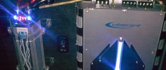
To this day, on the Internet, in various forums and blogs, there are heated debates regarding the need or uselessness of such a storage device as a capacitor. The debates themselves, to the great regret of car audio lovers, do not lead to any truth. They are completely useless, due to the fact that opponents do not even have a basic school understanding of physics.
Note. The biggest nonsense that can be read from forums is that you need to install a capacitor based on only farads per kilowatt. Such recommendations are fundamentally wrong, since you will not understand where they came from.
So, to lift the veil somewhat, let's go back to our physics lessons. As valuable knowledge is updated in our memory, all myths will disappear like morning smoke.
Differences between a capacitor and a battery
It is important to know:
- A capacitor for a woofer is the same power consumer that is not capable of generating electricity itself. But it is capable of accumulating it and then consuming it for its own leaks, but not for battery leaks;
- The capacitor's task is to accumulate energy and then release it to the consumer. The drive itself has extremely low internal resistance and for this reason “parts” with energy very quickly (by the way, it does not accumulate it slowly either).
Note. The difference between a capacitor and a battery is that the peak energy output of a capacitor occurs only for the first moment, and then there is a sharp drop in charge. Thus, the recoil speed drops along with the charge.
Differences between a capacitor and an ionistor
Capacitor for subwoofer
Ionistors are what most music lovers carry in their trunks. It differs from a capacitor in the following parameters:
- Huge losses;
- Greater resistance;
- Releases charge much more slowly;
- It costs several times less than a capacitor of the same capacity.
The optimal operating time of the ionistor is: 1 sec/83 cool.
Checking the ionistor
It is recommended to check the ionistor to clearly understand how it works:
- We connect the ionistor to the speaker system with power drawdowns;
- We start it up and observe that the voltage at the terminals increases. So far so good;
- We increase the volume and notice that the voltage drops from 13 to 10 volts.
Note. All this means that at the first hit of the subwoofer, the charge will drop and the ionistor will turn into an extra power component, since it is useful and active only when its charge is greater than the voltage in the network.
This situation among car audio enthusiasts is called sag, but it can be much worse if thin, low-quality wires and cheap copper-plated aluminum are used in the power supply. In this case, cable subsidence is also added to the normal subsidence.
Note. You need to know the dangers of cable sag. The fact is that with a sharp increase in consumption, reactance occurs. The more and faster the user tries to take energy from the cable, the more it (the cable) will interfere with this (if it is thin and long).
The problem of a cheap and low-quality cable will also be reflected in the ionistor, which, having discharged, will no longer be able to receive energy.
↑ What did installing an upgraded power supply in the amplifier give?
The improvements in sound are such that in further experiments I no longer returned to the original power supply.
The relatively large capacitance of the capacitors shunting the power circuit ensures good transmission of low frequencies. With the power supply from the Peter Smith amplifier kit (Sp = 4700 μF), the lower limit of the passband with a load Rн = 4 Ohms is 16 Hz, and with the proposed unit (Sp = 18800 μF) - 4 Hz. An alternative to high-capacity capacitors along the power supply circuits is to install a powerful voltage stabilizer with low output resistance, but this will be a design of a different level of complexity.
↑ Setting up
After checking the correct installation on the board, it is connected to the power transformer T1, and the outputs of the power supply are loaded with four resistors: ±25 V outputs with two 300 Ohm, 5 W resistors, and ±15 V outputs with two 510 Ohm, 1 W resistors.
Switch SA1 supplies voltage to the primary winding of transformer T1, measures alternating voltages on the secondary windings and constant voltages at the outputs of the power supply; they must correspond to those indicated on the circuit diagram. If everything is in order, the power supply is ready to work as part of the UMZCH.