Laboratory work "Introduction to Class D amplifiers." On the desktop IRS20957S, IRS2092S and TDA8954TH.
What do you think is shown in the photo? So, we don’t give hints from the back rows!
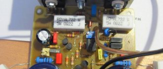
In the meantime, we are looking in a search engine for the inscription on the board, I will tell you what it is. This is the UcD250 module from Hypex Electronics. Nothing special. Class D, 250 W declared power. Normal, right? Have the Chinese painted their Watts again? No, today everything is honest and real. This is the insides of the EveAudio near-field monitor, designed for professional studio work. The size of the module can be estimated from the photo; for scale, use a regular AA battery.
Contents
- 1 Breaking stereotypes 1.1 Where are the lamps? Where is the Class A iron, the powerful power supply in the end? How disrespectful is this to the audiophile approach?
- 1.2 How so? This is a club-street speaker, this amplifier cannot sound like that! Especially class D!
- 1.3 How does it even work, is it painful? Where does 300 W from the PSU go? What is going on?
- 1.4 Start of the laboratory
- 2.1 Power supply 2.1.1 Power supply circuit
- 3.1 Power supply
- 4.1 Behringer Eurolive B112D fire
INFRARED (IR) SENSORS
Infrared sensors are increasingly used in temperature measurement in applications as diverse as automotive climate control, ear thermometers, home insulation measurements, and engine diagnostics for vehicle repairs. The fairly small sensor output requires high gain with minimal offset voltage and minimal drift to avoid DC error. If AC coupling is used between the gain stages (Figure 5), low offset and drift avoids the input gain stage from saturating as a result of drift.
Rice. 5. Amplifier for infrared sensor
Low input current provides minimal error with high sensor output impedance. As with pressure sensors, the very low level of time and temperature drift of the amplifier avoids the introduction of additional errors after a single calibration has been performed. Low 1/f noise improves signal-to-noise ratio (SNR) for DC measurements with sampling periods greater than 1/5 second. In Fig. Figure 5 shows an amplifier circuit that amplifies a signal of 100-300 μV to a level of 1-3 V.
↑ Breaking stereotypes
↑ Where are the lamps? Where is the Class A iron, the powerful power supply in the end? How disrespectful is this to the audiophile approach?
It's simple.
We live in an environment of stereotypes imposed on us by some gurus or authorities. Since he said so, it cannot be otherwise. Therefore, you cannot screw a UPS to the lamps, you cannot use an op-amp like the NE5532, and the capacitor in the path must be the mythical BlackGate. Why doesn’t anyone dare to wonder what’s going on in the studio? What kind of op-amps and power supplies are there in consoles and digital tape recorders? How are the wires from microphones and instruments polished? And are they polished at all? Are they turned on correctly and what brand of XLR connectors were used? Where are the wires located? What about the power cords? Is it at the right angle? But in vain. This information should sometimes be written on album covers in small print in order to sober up particularly zealous listeners. There, in the studios, everything is a little different...
Class D rustled its hooves past me. I, too, sinfully, being captive of stereotypes, considered it the destiny of music centers and boomboxes. Yes, I’ve seen them in precision (!) motherboard stabilizers, and I even once assembled 220 V inverters - they’re also essentially class D, but I didn’t use them for sound. Exactly until the HK-Audio HK Linear5 115FA active speaker module came in for repair.
I was surprised by the dimensions of the entire board, and the fact that it is a two-way speaker with a power of about three hundred real watts. The problem was in the power supply, but the amplifiers for the low-frequency and high-frequency sections were alive and well. But it was simply necessary to check after launch. To do this, the Jeff Rowland clone that was working at that moment was disabled and a module from HK was inserted in its place.
The result impressed me! I've heard statements that the amplifier must be an order of magnitude more powerful than the power used, but to express this so much?
↑ How so? This is a club-street speaker, this amplifier cannot sound like that! Especially class D!
Later, I was convinced of this more than once when I listened to 2-3 kilowatt amplifiers on my working 50-watt speakers, but the first impression was strong. And most importantly, it is fantastic efficiency. The field devices at the output are on small plates on the left in the photo, the power supply is on the TOP262 on the right, the RF section is in the form of a submodule without radiators at all, cooling - there is one 50 mm fan for all and almost no holes. And it doesn't get hot! No, it heats up, up to forty degrees after an hour of work!
↑ How does it even work, is it painful? Where does 300 W from the PSU go? What is going on?
The first impression was very difficult.
I’m used to trusting my eyes and hands, and not the letters in the picture, so I listened to this module in different modes for several days, touched it, turned it on, off, and measured temperatures. Ultimately, academic interest won out and I decided to take a closer look at this technology. It turned out that class D has been firmly established in our lives for several years now, and at the same time has good characteristics. For example, the UCD (Universal class D) technology itself, simply put, is a conventional amplifier put into self-excitation mode, and an analog signal modulates the pulse width of this excitation, and at the output we have a PWM-modulated audio signal with the frequency of this self-excitation. Then, using a choke and a capacitor, we convert it back to analog.
Now it’s clear how laptops get voltages with three decimal places.
Of course, there is a set of specialized microcircuits and field-effect transistors, as well as many ready-made solutions. For example, the IRAUDAMP series from the former IR, and now Infineon.
↑ Start of the laboratory
Why not do laboratory work to study the principle of operation, underwater rakes, unexpected discoveries and more. The range of equipment that I managed to touch is quite wide, but, as a rule, it is either an NXP product with their TDA895x, or IRS209xx from Infineon in different variations. IRAUDAMP6
and
IRADAMP7
were taken as a basis on the wonderful
IRS20957
and
IRS2092,
respectively.
By chance, I received a faulty Behringer iNUKE NU6000
, so a batch of IRS20957 and IRFB4227 were purchased to revive it. This determined the choice of circuit design. At the same time, the task was not to create a “kilowatt from a channel into two ohms” - I simply had nowhere to use “this”, and I held real pieces of hardware for “kilowatts” in my hands, and darned them after drunken DJs and lame electricians, and, naturally, listened and assessed. So I didn’t lay down the power, didn’t measure it later, and didn’t announce it. Somewhere around “one hundred watts” would be a more accurate description of the technical specifications. For the same reason, limiters were not installed; they are not needed at home.
Well, go ahead!
PRECISION CURRENT SHUNT SIGNAL MEASUREMENT
The performance of a precision current shunt is greatly improved by using the unique advantages of an auto-zero amplifier connected to an instrumentation amplifier circuit (Figure 3). Current shunts are used in precision current source circuits as an element of the feedback circuit. They are also used in many other applications, including battery-powered current sensing circuits, motor starting current monitoring circuits, and precision electrical power sensing circuits.
In this circuit, it is desirable to use a shunt with very low resistance to minimize the voltage dropped across it; in this case, power losses will be minimal and when measuring large currents, the voltage due to the shunt will drop slightly.
Rice. 3. Current shunt amplifier
A typical shunt may have a resistance of 0.1 ohms. When measuring a current of 1 A or more, the shunt output signal will be hundreds of millivolts or even volts, and the amplifier's DC error is not critical. Another thing is for small measured currents, about 1 mA: for a sufficiently accurate measurement of a voltage of 100 μV from the shunt output, an op-amp with a very low bias voltage and with a very small drift of this voltage is required. It is also necessary to have a minimum output leakage current so that it does not introduce a noticeable error into the measured signal. High open-loop gain, common mode rejection ratio (CMRR), and power supply rejection ratio (PSR) contribute to high system accuracy. If the current does not change too quickly, then using an auto-zero amplifier with a fixed frequency auto-zero circuit can achieve excellent results.
It is usually desirable to limit the frequency bandwidth of the signal being processed to the minimum required value, since this minimizes the influence of impulse noise of the autotuning circuit, and in addition, minimizes the overall noise level. Remember that the total voltage noise of an autozero amplifier is proportional to the square root of the bandwidth (EN=eN * vBW). A simple low-pass filter can be created by adding additional capacitors (C) in parallel with the feedback resistors. Additional amplification and filtering of the amplified signal can be achieved using an additional stage with a conventional operational amplifier. An autozero amplifier with its inherent high gain and open loop feedback can provide 100x or 1000x gain, allowing the next stage to use a low-cost CMOS amplifier with a few millivolts of offset voltage and high voltage noise without compromising system accuracy. . In addition, using a high-gain stage on a self-zeroing op amp can provide an additional pole and a faster roll-off of the filter's frequency response if the op amp's gain-bandwidth (GBW) product divided by the set gain results in a value less than half the operating frequency. zero compensation circuits. However, the characteristics of the resulting filter will depend on the GBW, and the value of GBW varies among different amplifiers.
If the signal frequency exceeds approximately half the frequency of the zero compensation circuit, then it is better to use an amplifier with a pseudo-random clock generator, such as the AD8571. In this case, the broadband noise will be somewhat larger and have a wider bandwidth, but the loop-loop clock will not cause peaks at the clock frequency, and intermodulation effects (IMD) will be minimized.
↑ Amplifier 1. IRS20957+IRFB4227 (IRFB5615)
An amplifier using IRS20957, built on the basis of IRADUAMP6, is an external op-amp integrator that directly PWM modulates the input signal, the IRS20957 upper and lower leg driver itself, and the output stage on two field devices. All this is covered by feedback, which triggers self-generation at a frequency determined by the integrator wiring elements.
The driver also contains upper and lower arm overload protection, as well as soft start and four adjustable dead time values.
This topology is called self-oscillating amplifier
. You can use an external generator, but more on that below.
↑ Power supply
First we needed to create a power supply unit. The fact is that this driver requires several voltages for proper operation. The driver's PWM signal input requires a TTL level, which means the integrator must be powered from +/-5V, and the driver itself must be powered at +12V, not relative to the common wire, but relative to the negative power supply bus.
In demo boards, this problem is solved a little clumsily, and 12V is obtained using a stabilizer from the negative bus, and then they vigorously fight against excess heat generation. I decided not to go through the rake at least in this matter.
Since greater power is not planned, the battle-tested FSFR1700 power supply is taken as a basis. Its power is enough for me to use at home, and almost all the components are in stock.
I imagined the future circuit design in general terms, so I set the following parameters: 12V driver power supply, relative to the negative bus. It is also stabilized by the BP OS. The power supply of the amplifier itself is 2*40-60V. And 2*12V for the buffer. I planned to power the integrator through primitive 5V resistor-zener diode circuits, which played a cruel joke on me during testing.
↑ Power supply diagram
doesn't bring anything new.
Since the resonant power supply voltages are multiples of approximately 6V per turn, I chose the amplifier supply voltage to be 55-58V. The above does not make sense due to the 80V capacitors available. pumping effect
occurs in class D amplifiers , it is simply impossible to bring the power supply too close to the operating voltage of the capacitors.
↑ Pumping effect
Pumping effect
on fingers. The energy accumulated in the choke at the output of the amplifier flows into the power buses through the internal anti-parasitic diodes of the output field switches, causing an increase in the voltage on these buses. It is especially pronounced at low frequencies, on signals of a periodic shape, such as a sinusoid. You can read in more detail in specialized literature.
At the dawn of commercial production of class D amplifiers, Schottky diodes were installed in the power supply circuit in the forward direction. This made it possible to eliminate the pumping effect, but at the same time an extra component appeared in the circuit. It’s hard to say which was better - to use capacitors for a higher voltage or a pair of diodes, but now there are no diodes, the capacitors are end-to-end and the channels are out of phase. Apparently this is better? Or cheaper?
In the first version of the amplifier, stabilizers DA2, DA3 were set to a voltage of +/-9V. Next, two boards were made from scrap materials. To power the integrator, I used chains of 1.2K resistors (I just had them lying around) and 5.1V zener diodes.
At idle, before installing power switches, drivers and op-amps into the board, these voltages corresponded to the norm and I calmed down. But in vain. That’s how much I didn’t like these “simple” solutions, that’s how it turned out. As a result of the tests, four field workers and three drivers were burned out. The current power supply saved me from more serious damage. She simply turned it off.
But everything turned out to be banally simple. When installing the op-amp, I did not measure its supply voltage. I'm used to the fact that the LM317 won't let you down. But the resistor will fail. The voltages turned out to be +3.2V and −3.8V. Not every OU will work when it is so underfed! I threw out the resistors, calibrated DA2 DA3 to 5V and that’s it. Startup, frequency is in place, the power supply is not cut off. I’m such a jerk sometimes...
↑ Amplifier circuit
The amplifier boards were a little tired from my torture, so I decided to redo everything. Now version 1.1.
Mono-board for two channels, protection against constant voltage. Although there is built-in short-circuit protection inside the IRS20957, it’s somehow frivolous to risk the speakers with a supply voltage of 60V. In professional equipment, the protection extinguishes the power supply, I don’t have such a mode, so the usual protection is against constant power supply on the relay.
A dual op-amp is used as a buffer and integrator. A buffer is required. You can give them a sense of instinct (and here playing with the value of the OS resistors R9 R40 is fraught with loss of stability and further loss of keys and driver). They can untie the amplifier from the source.
Separate adjustment of the generation frequency has been made using resistors R6 R37. With minimal resistance, the frequency is minimal, about 80-90 kHz. The frequency can and should be increased, but without fanaticism. I have a terminal mount, and experiments at such frequencies are unsafe. It’s simpler on SMD, but you should remember about through currents and the thermal regime of the driver. I set it to about 320-340 kHz.
The circuit on transistors Q1, Q2 is smooth on and off. There is a delay of 5-6 seconds when turning on, and shutdown when there is a power failure from the power supply. In general, anything can be applied to the CSD output, from MUTE to thermal protection.
Pin 8 sets dead time
. The dumber the fielders, the greater the DT value. I abandoned the IRFB4227 in favor of the lighter IRFB5615, since on the IRFB4227, when the volume was increased, it went into protection at the average DT value. And maximum DT and low frequency are the destiny of amplifiers for subs. I don't have subs. Therefore, the settings will be different.
In general, all recommended parameters are in the update notes or descriptions for IRADUAMP. For example, how to set up protection and how to set DT. I won’t tell you, there is one table on DT and several simple formulas for the values of protection resistors. Resistors must be changed when the amplifier is turned off and the capacitors are discharged. When generation is turned off, there is no flow through the power buses, the tanks last a long time. This is how I killed another IRS20957.
↑ Important note
It is advisable to have an oscilloscope to configure the amplifier. If everything is collected correctly, then he will earn 100%. But it’s difficult to set the frequency without a device. L-meter is also desirable. Since the output choke is practically the main part.
↑ Throttle
In this version, a ready-made choke from the HK Linear5 115FA amplifier unit is used. Inductance is approximately 28 µH. Wound on a red
ring. I didn’t find any similar rings in my trash. Yellow rings from computer power supplies are not suitable. People recommend either ETD or RM cores. Or just a rod. The rest goes into saturation. Do not forget that all active and reactive power goes through the inductor.
There are programs online for calculating such chokes, so you can calculate it “by eye” without an L-meter. The filter parameters determine not only the cutoff frequency and frequency response, but also the remainder of the carrier at the output. At the AC terminals the remainder is usually 200-500mV. To some this seems like a lot, but remember that these are 200-400 kHz, we don’t hear them and not every speaker reproduces them. Well, the whole world around us has long been modulated with chargers, energy-saving devices and wi-fi points.
INTRODUCTION
When it comes to amplifiers with automatic zero correction (amplifiers with chopper stabilization, the so-called chopper), the question inevitably arises: how do they actually work? In addition to being curious about their internals, many engineers may be asking the following question: “Their DC accuracy is impressive, but what strange behavior might I encounter when using these amplifiers in my circuit, and how can I avoid problems?” In this article we will try to answer both of these questions. Some common applications of these amplifiers will be given to illustrate the significant advantages, as well as some of the disadvantages, of these components.
↑ Amplifier 2. IRS2092+IRFB4016
Electo-Voice ZXA1
speaker (by the way, there is a power supply on IR2153!). I had to look for a floating defect, and out of fear I purchased IRS2092 and IRFB4016 for them. The defect turned out to have nothing to do with semiconductors - ceramic capacitors are evil, and I decided to build an amplifier using IRS2092.
I decided to make this option solely for comparison. Since the IRS2092 has a built-in integrator, it is actually a full-fledged amplifier.
But I decided to use an external generator.
As in the above AC. No, the topology remains self-oscillating
, but only the frequency is synchronous with the external source. And the phase is opposite in both channels to reduce the pumping effect. In addition, an OOS has been added to the amplifier, which can be removed after the throttle. In the original, the frequency is rigidly set and equal to 250 kHz, but I decided to make it possible to adjust it.
↑ Power supply
And then again we had to make a power supply. I didn’t make a clone of the previous one; I mercilessly dismantled the 6E5P tube hybrid. PSU on FAN7621.
Everything is almost the same here. I just didn’t pull out the protection on a separate winding and powered it from the +12V bus through a stabilizer. The 6V supply voltage was chosen because I had 5V relays available. For others, the voltage relay will have to be adjusted. I also lowered the supply voltage of the amplifiers to +/-38V. We've run out of containers. Only 50V left...
↑ Amplifier circuit
The amplifier itself is also somewhat different from option 1. Single op-amps as buffers. Here they can already be powered from +/-9V. I didn’t go any higher, so as not to load the stabilizers on Q1 and Q2. A soft start from the power supply was also not useful. The amplifier turns on and off silently.
The reference frequency generator is assembled on HEF4047.
I planned to do it on something like 74AC04, but to my surprise I found 4047 in the trash... The frequency can be adjusted via R17. Interestingly, upon first startup, the amplifier refused to operate at frequencies below 200 kHz. Launch, chaotic generation and defense. It was nice to be able to adjust the frequency on the go. I raised it above 200 kHz and everything worked! I can’t say yet what this is connected with. The IRS20957 did not have this; the output was stable from 80 kHz. I worried in vain and measured all the voltages several times before installing the field devices and driver. After turning it on, everything worked the first time!
↑ Chokes
I picked it out from some power supply unit.
Were at 60 µH, rewound to 22 µH. It turned out to be about 24 turns. The wire is about 2 mm. I want to try to shake the litz, but then.
↑ Recommendations for setting up
There is an application note for both chips.
They indicate how to correctly configure short-circuit protection, how to set the dead time value, and how to select piping elements to set the frequency. In general terms, nothing complicated. For example, we configure protection for the field workers used. The setting is rough if you use a standard range of resistances. If there are precision values, it will be more accurate. The choice of DT also depends on the field workers and the frequency. For example, for stupid but powerful IRFB4227, it is better to set the maximum DT and not increase the frequency above 180-200 kHz. But for light field workers, on the contrary, you can increase the frequency and reduce DT. The higher the frequency, the higher the quality of high-frequency transmission. Almost like a DAC. But it is impossible to drive the frequency up to megahertz. There will come a time when the field gates stop closing and drafts begin to appear. DT won't help here.
If everything is assembled without errors, the circuit starts the first time; as a rule, only the frequency needs to be adjusted. Or solder in the required resistor in advance. The rest works right away. If in doubt, you can hang light bulbs on the power rails. Somehow I didn't need it.
At startup, at the point of connection of the field workers, before the throttle, it should be something like this (divisor 1:10 span - two supplies):
Or like this, without a divisor:
And after the throttle like this (without a divider).
The carrier level depends on the frequency; the higher it is, the lower the level. You can reduce it at the current frequency by increasing the inductance or capacitance of the filter, but you should remember that you can cut off the frequency response from above. So fanaticism is undesirable here.
I think it is possible to use a T-shaped filter and improve the cutoff, but in reality I have almost never seen the use of two chokes at the outputs, and those that had a second stage were more likely to filter noise from the cable into the amplifier than from it. It is also good to use such amplifiers as a low-frequency section - such as a subwoofer or low-frequency channel. With such efficiency, the amplifier will have no equal.
↑ Measurements
All this is good, but at this stage we need to measure ourselves against something. It doesn’t matter what or how, but without measurements, all my stories and praises will be incomplete. With a trembling hand I take out the moth-eaten Creative X-FI HD and try to measure what I have sculpted. According to tradition - measurement along the ring.
As you can see, the instrument is still capable of a lot, although it has already been in unequal battles with amplifiers, which I talked about in previous articles.
A slight incident arose with measuring the amplifier - the fact is that I lost my load PEVs during the process of moving, so I use two 6R 5W resistors in parallel as the load, which gives the measurements a certain charm. Turned it on, adjusted the levels, turned it off. Because the smoke from these heating resistors begins to obscure my eyes and I’m afraid that poor Creative will step on the same cake, but through my fault. But I can’t forgive myself for this.
First you need to measure the big picture:
And, as it turned out, it is quite good for a pulse amplifier assembled using fecal-dendral technology on the knee. This is the best result after a number of attempts until the load resistors overheated. It’s only worse when the ADC is overloaded or when the power is reduced while maintaining the threshold of -2-5 dB. The noise is already growing there.
What about the frequency response? Well, primitively, using freq sweep, I observed it. Some “sinusoidality” of the picture is a feature of the program - in reality it is linear up to the measurement limit of the card.
That is, my fears about a decline from above due to the filter after the field workers turned out to be groundless.
These measurements are given for the first version, which is on IRS20957, the second, which is on IRS2092, turned out to be slightly worse in terms of THD level, but more pleasant in sound (this is a deception that we sometimes take for the best).
Now here's an interesting observation
: The THD level, or rather the harmonic level, changes as the carrier frequency changes. And not in both channels, but on the contrary - in one it can increase, while in the other it can simultaneously decrease. Apparently the generator should be of very high quality, and ideally it should be quartz-coated. Then the picture will be different. At this stage, self oscillated looks better in terms of measurements.
Something like this.
↑ Important note on power supply
The fact that I used a stabilization system to obtain +12V driver power is fundamentally incorrect from the point of view of designers of professional amplifiers. Voltage stabilization using the OS is never used anywhere. The power supply, whether it is resonance or just PWM, operates at maximum output to the load. The control is used only to turn off the power supply in the event of an amplifier failure. The relay is used as a load break only in older versions of amplifiers. All new ones, in the event of an accident, extinguish the power supply without breaking the load.
↑ Important note on printed circuit boards
The power supply buses of the same name are connected on the reverse side by ordinary wires. These connections are not indicated on the trace! Be careful when assembling.
↑ First impression of the sound
- great dynamics.
Especially noticeable at the bottom. Option two has a softer sound in the mid-treble area. The influence of the second OS circuit is possible. I had a similar feeling from the dynamics when I ran the Dynacord L2400 at a power of 15-20 watts after repair. It was simply impossible to get louder; I would have to leave the room.
Second impression of sound
- if you don’t know what’s there in front of the speaker, you won’t guess. Before this, the difference between a lamp and an AB was easy to calculate. The power reserve is clearly felt here, it’s difficult to describe, you need to listen. The device is “transparent” for any genre of music.
But the most “difficult” impression
— nothing heats up! That is, the trans in the power supply is heating up - this has always been the case, slightly warm chokes are also normal, and the rest is at room temperature. And why did I fence these aluminum plates, put a bunch of radiators everywhere where they weren’t needed? I understand, it's a habit. Especially after lamps with their “high” efficiency.
But there’s just a feeling of unreality, as if it’s just turned off and doesn’t work... Naturally, if you remove hundreds of watts from these amplifiers, then it will heat up, but for the home, when there is no war with neighbors and the remains of the ears are still needed, all the aluminum is from these boards You can safely hand it over to non-ferrous metal - the amplifier won’t notice it. And in the SMD version it will generally be very compact, as in the photo at the beginning of the article.
In general, class D does not end with the designs described above. Your smartphone is 99% equipped with a Class D amplifier, just a small one. Car amplifiers, music centers, televisions - this is only the “initial” stage of using this technology. Power supplies for digital units of laptops, tablets, cell phones, wherever you need to get, for example, 1,200 V to power logic, rather than 1.2 V ±10%, work on a similar principle. And they work great.
BRIDGE STRAIN GAUGE SIGNAL MEASUREMENT
Another application where low DC offset and corresponding low frequency performance helps achieve high dynamic range is in bridge sensor applications. These sensors are used in force and pressure measurements, as well as in electronic scales; they usually produce a relatively low voltage output, even at maximum load. In this example, three of the four amplifiers available in the AD8554 are used to drive the sensor and differentially amplify the signal (Figure 4).
Rice. 4. Load cell connection diagram
The maximum signal of the strain gauge is several tens of millivolts. In this case, the very low offset voltage of the amplifier with auto-zero correction helps to minimize the error of the measured signal. Due to the absence of 1/f noise, it is possible to sample the input signal at large intervals. Since the level of time drift of the amplifier is quite low, recalibration of the device can be done less frequently or, in some cases, not done at all.
Pressure sensor applications that typically require linearization to obtain an accurate output signal benefit from an amplifier with low offset voltage and low offset voltage drift. A signal from a well-performing sensor can be scaled and linearized without taking into account the influence of the amplifier, since the additional errors introduced by the amplifier are negligible. The amplifier's low input current allows the use of high-impedance sensors; This can significantly reduce system current draw in portable or signal-loop powered devices, since the drive current of the sensors can be much lower for the same output voltage. The lower excitation current also minimizes errors associated with self-heating of the sensor. Most strain gauge devices are low-frequency in nature, so the limited operating bandwidth of auto-zero amplifiers and fixed-frequency auto-tuning circuitry is not a problem. When using a higher output frequency bridge sensor or an AC-excited sensor, it is recommended to use an autozero amplifier with a pseudo-random clock (AD857x family).
↑ Amplifier 3. TDA8954TH
When everything was already written and ready for publication, a device suddenly fell on me, allowing me to effortlessly try another version of the class D amplifier on the TDA8954TH. This series is now widely used in professional audio equipment, as well as in high-quality household equipment, but, surprisingly, is not popular among DIYers. Try typing the name in the search - you will be surprised.
↑ Fire in Behringer Eurolive B112D
I had a chance to “touch” them all from TDA8950 to TDA8954. But, as a rule, it was a bridge in the low-frequency section of the device. I needed an amplifier in stereo mode, and a broadband one at that. And now the opportunity has arrived! The donor is an active speaker Behringer Eurolive B112D. Fire on board:
Surprisingly, everything survived, with the exception of the components that burned into trash.
Only the physical destruction of the board allowed me to tear it apart for experiments. The reason is poor-quality containers in the outlet piping. The manufacturer sent a new module in its entirety, and from the “old” one I assembled a “knee-high” version of the amplifier.
↑ About the features of the TDA8954TH chip
The TDA8954TH is a class D stereo amplifier. A mountain of advantages!
The case is still solderable; competitors already have cases for robots. Ability to operate in stereo and bridged mono mode. Bridge mode tends to be popular with manufacturers. There is a built-in carrier generator, as well as the ability to operate from an external one by dividing its frequency by two. The manufacturer, to improve quality, strongly recommends using an external generator. Let's try and see.
Works with zero Deadtime, so the efficiency is still slightly higher.
It is equipped with a powerful protection package, and during testing, I was not able to deliberately disable it with crooked hands - damn, I really wanted to! The short circuit at the output holds well, when it overheats, it sticks in an overheating flag and reduces the gain - and then either turn off or start the fan - the flag was given to you.
Minuses:
inconvenient body, inconvenient footsteps for highly loaded circuits and power circuits. Although in general the topology is almost symmetrical. There is a heat sink plate on top, which is somewhat inconvenient when mounted on standard racks without a special heat-conducting plate. Another disadvantage is that the output circuits require a bunch of SMD capacitors at a short distance from the chip, which is not always good - good high-voltage ceramics are in short supply.
↑ Amplifier circuit
So the diagram:
The generator is assembled according to a proven circuit on the HEF4047, with the exception of the frequency - it is twice as high as the previous amplifier.
Since there is a divider by two inside the microcircuit, the generator frequency should be in the range from 500 kHz to 1 MHz. I drove up to 1.2 MHz - everything is fine. Q1,Q2 - soft start circuit. Generates a 0-5V signal on the MODE leg when power is applied or removed. For more details, see the datasheet. |Q3 - indication of overheating protection. Does not turn off the output, but suppresses the signal swing at the output. Q4-Q7 - switches off the speakers in case of any accident in the amplifier, as well as in case of short circuit, overvoltage, overcurrent, and so on. The full list of flags is in the datasheet. When turned on, there is a delay in connecting the speakers, as in a conventional amplifier.
At the input there are two op-amps as buffers and symmetrical signal shapers. The amplifier channels are turned on in antiphase to reduce pumping, so for correct phasing of the speakers, one channel is turned on “in reverse”. In principle, this can be done on the output connectors when installed in the case. The op amps are powered from the amplifier's power buses via LM317/LM337. Yes, it’s hard for them, but in the power supply the engineers, unlike me, did not provide a separate output for powering the op-amp. And since I used a ready-made set of spare parts, I had to follow in their footsteps.
↑ Power supply
In general, the idea was to cram the amplifier into a DAC case format, 200*200mm in size, and two corner radiators contributed to this. Therefore, the power supply unit and the amplifier itself are made on two boards.
The BP was taken entirely from the donor. Only the thermal protection component was removed and the stabilizer was changed to 5V. Since I don’t have data on the transformer, I won’t describe it in detail. Controller NCP1271.Flyback topology. The controller is definitely smarter than me. I still haven't fully figured out how it works.
I don’t see the point in drawing a diagram without talking about the transformer, the output is 2 * 38-42V (adjustable), and 5V is stabilized for the protection, generator and starting circuit. Here is a piece of the service manual for your reference:
↑ Switching on, adjustment, measurements
If everything is assembled and soldered correctly, everything works the first time you turn it on.
You only need to adjust the frequency of the master oscillator with resistor R25. A lot of interesting things come out here. For example, standard chokes get quite hot. There is nowhere to shove the non-staff - there is no space. The efficiency of a resonant power supply is higher than that of a flyback, LM317/337 with a load of two op-amps and two LEDs significantly heat the radiator plate, and the microcircuit itself does not participate in heating. Therefore, either throw out the buffer or make a separate winding for their power supply. But overall, it sounds great even on the knee:
The same effect is observed here as in the IRS2092 amplifier. External clocking produces a harmonic level that exceeds the datasheet value. Apparently the quality of the carrier is the determining factor for quality indicators. This means that to seriously improve performance characteristics, you need to use a better generator, ideally quartz.
But by ear it is not noticeable. My deafness does not allow me to draw a clear conclusion, but the overall impression is positive. It’s especially unusual to flinch when you turn up the volume along with the furniture in the room - the feeling of the power reserve is indescribable, given the modest dimensions of the device.
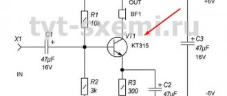
Schematic diagram of ULF
Schematic diagram of the amplifier on the TDA7498
The module is powered by a voltage of 24 volts, filtering - 2 capacitors 2200 μF. In addition to the power supply and UMZCH, there is a speaker turn-on delay system and a level indicator. When listening, we are very pleased with the sound of the amplifier, but the weak power supply (the transformer is not so hot) does not allow us to reveal the potential of the TDA7498. The LED above the switch is two-color; when it is turned off, it lights up red, and when the ULF starts, it lights up green.
The TDA7498 stereo amplifier is pin-compatible with the TDA7492 (2×50 W), TDA7498L (2×80 W) and TDA7498MV (100 W) amplifiers, which allows the use of a similar hardware platform for ULF with different output powers.
↑ Reflections and conclusions
We live in a world of stereotypes.
Some consider the 4A32 the crown of creation, not suspecting that in good modern 30 cm speakers the moving system can weigh less than 30 grams. Someone sleeps with a 6P3S lamp under their pillow. Someone heats their house with class A, removing 10 W of useful power at the output. Particularly stubborn people polish the wires, forgetting about the thousands of semiconductors on the way from the CD player's laser to the DAC output. My comrades also told me that I had betrayed the idea... But I never asserted anything without listening and trying, on the basis of someone else’s authoritative opinion. What's your head for? I usually check and listen. So this is my opinion about class D - super! Technology that we once sorely lacked.
One day, an old friend of mine, with whom I went to school, came into my office. Common interests in technology, but different paths in life. And I have a converted 1983 S-70. All that was left of the speakers were the woofers and filters. I simply threw the rest away, which I don’t regret at all. I just couldn't get the speakers yet. The tweeters are new - isodynamic, the old ones were pierced by children. The enclosures are custom-made, ~140 liters, bass reflex, each assembled weighs about 50 kg. I test amplifiers on them. Well, of course I listen in the background.
“Do you remember,” he said, “we used these speakers to pump up the gym at school!” “I remember,” I answered, “but do you know what we really lacked then?” - What? - Class D! — Yes, I wish I could rewind 30 years, remove someone’s home “Amphiton 101” + fan and put a device the size of a book on the table. - And tear everyone apart!
At this stage of development of sound reproduction equipment, the weak link is not the amplifier or the source. These devices have long surpassed the capabilities of human hearing in their characteristics. The most problematic thing is the speaker. Especially, as we like - broadband - cheap and cheerful. Manufacturers' promise, frequency response measurement - how it turns out depends on the case and overall implementation. In reality, the sound is influenced by so many factors that getting an equivalent speaker THD below 1% in the midbass is already a serious problem.
The middle and top - they have almost decided - with the same electrostats or a serious reduction in the mass of the moving system with a simultaneous increase in strength.
The size of the room and standing waves are a quest; car enthusiasts love to solve it every day, increasing the power of the amplifiers, the size and weight of the speakers, because there is no other way to fool physics.
And what a delight the resonances on diffusers are - anyone who has encountered them will not let you lie.
Therefore, I want to express my opinion - these amplifiers are in no way inferior to a good class AV amplifier, with the exception of better low-end response and smaller dimensions of the case itself. And in terms of efficiency, they tear everyone apart.
And this is a “laboratory”, I did not expect much from these devices. If performed well, the parameters will be even better if you set this as a goal.
That's all I have for now. Thank you for your attention!
PS
Recently I noticed that manufacturers of audio equipment began to proudly write
“Class D”
.
But “SMPS”
was never written. Strange, right?