Final HF amplifier on GU-50 without power transformer
Lightweight and powerful short-wave tube amplifier - UM-300-M1“Readers who are confident in the danger of PA without a large and heavy power transformer, I ask you to believe (for now in word, but after reading to the end: I hope in practice) that the isolation from the network of a well-designed power amplifier is no worse (and can be done even better), than that of a conventional transformer." Although these words instill a subtle shade of doubt, they belong to I.V. Goncharenko, a well-respected engineer, designer, and also the author of numerous publications devoted to the issues of analysis, calculation, design and application of HF and VHF equipment. The full justification for the above postulate is given on the author’s page – https://dl2kq.de/pa/1-1
An example of the successful implementation of such an approach to the design of powerful tube HF amplifiers is the design of V. Gladkov (RW4HDK) from the glorious city of Chapaevsk. Here's what the author writes:
Lightweight and powerful HF amplifier UM-300-M1 without a power transformer
I was prompted to create this power amplifier for the HF transceiver by the well-known publications of such famous authors as Y. Lapovok (UA1FA) and I. Goncharenko (DL1TT). The goal was to produce a light, small-sized and powerful RA, but the use of generally accepted techniques does not allow fulfilling all these requirements. In addition, a parallel-powered PA requires very careful implementation of the anode choke, and its “return” in the HF ranges strongly depends on its own capacitance and on the installation capacitance, i.e. its efficiency decreases. A circuit with sequential power supply is largely free from these shortcomings, although it places increased demands on the quality of installation and on the electrical strength of the radioelements used. But you must admit: it’s better to spend a little more time, effort and money than usual, but in the end get a good product that you don’t have to constantly fiddle with a soldering iron or strain your stomach trying to move it from its place as needed.
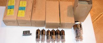
The most common lamps are GU-50, so we’ll focus on them, although you can use something else, but the cost-benefit ratio is still optimal in this option.
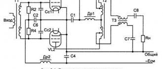
Fig. 1 Schematic diagram of a tube HF amplifier without a power transformer
The anode circuits are powered by tripling the mains voltage. This will be about 930 volts, which is quite enough, because... There is no such thing as a “dip” in voltage at signal peaks in this circuit, whereas in the “classical” circuit you cannot get rid of it, and usually these 900 volts are present at the anodes of the lamps instead of the required 1000...1200.
The capacitance of capacitors C11...C14 must be at least 200 μF for an operating voltage of at least 350 volts. In addition, they must have the same leakage voltage. In this regard, capacitors from Samsung are the best choice; they do not require selection, just like any other imported ones. Resistors R4…R7 – MLT-2 150k (200k).
Variable capacitor C1 is a triple-capacity capacitor of 15...500 pf, in which movable and fixed plates are “threaded” through one. Its stator is connected to the tap from the first turn of coil L1. Exactly the same KPI is used at the “cold” end of the P-circuit, but its plates are not removed.
All winding data is shown in the figure, with the exception of the P-circuit. L1 – 9 turns of MG-2.0 on a 40mm mandrel and a winding length of 65mm. Branches: from the 3rd turn (range 10m), from 3.5 turns (range 12m), from 4.5 turns (range 15m), from the 5th turn (range 17m), the entire coil - 20m range. L2 – 46 turns of PEV-1.2 on a fluoroplastic ring K70*30*15mm. Bends: from the 18th turn (range 30m), from the 20th turn (range 40m), completely L1 and L2 - range 80m. L3 (160m band) was not manufactured for the amplifier.
Resistor R1 must be present, because at the moment of switching on, a powerful impulse of the charging current of electrolytic capacitors occurs, which sooner or later will disable them, with all the ensuing sad consequences.
S1 can be turned on almost immediately after turning on S3, and S2 only after 5...7 minutes of warming up the lamps at idle.
The RK-75 braid of transformer T2 is soldered to the cathodes of the lamps, and a signal from the transceiver is supplied to the central core through C31. C31 is necessary in case, for some reason, an interturn short circuit occurs at Tr2. Thanks to it, the transceiver will not be damaged.
The braided RK-75 cable of the T1 transformer is also connected to the built-in KPI, and the output signal is removed from the central core and then goes through the SWR meter to the antenna.
Thanks to the use of the DA2 microcircuit, the quiescent current of each lamp is about 25...30mA. This allows you to slightly increase the efficiency of the amplifier and slightly improve its linear characteristics, but you can also take a simpler path by connecting the screen grids of lamps with minus 930 volts. The quiescent current of each lamp in this case will be about 10...15 mA.
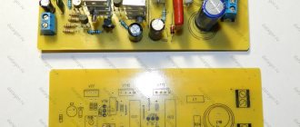
As for technology: the best option is to perform the entire installation on a single piece of one-sided foil fiberglass.
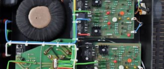
Fig.2 Top view of the amplifier
Fig.3 Bottom view of the amplifier
All mounting tracks are milled, and the rest of the foil serves as a common wire. At the points of attachment to the body, the foil is also removed to a width of at least 5 mm from the metal parts. All KPIs are mounted on the same PCB with the foil around the fastening bolts removed, and the handles are brought out to the front panel through plastic bushings.
Fig.4 Rectifier 930v (view from the tracks)
Fig. 5 +12v DA2 stabilizer is attached to the amplifier body through a mica gasket
Figure 6 shows the location of the controls on the front panel of the amplifier and the location of the connectors on the rear panel.
Fig.6 Front and rear panels of the HF amplifier
The dimensions of the RA correspond to the dimensions of the Ural-84M transceiver case (310*300*140mm), the weight is about 3.5 kg, which made it possible to place it on top of the radio station, creating a kind of “stand” and saving space on the desktop.
The amplifier showed excellent results. The RF signal is amplified in a ratio of 1:10 on ALL(!) bands, discarding the common statement about reducing the gain by 21 and 28 megahertz. By supplying 30 watts to the input, we get 300 watts; 20 watts is 200, and nothing else. (Measurements were carried out with an RF voltmeter at a load of 50 ohms).
Without radical modification of the amplifier, the anode voltage can be increased to 1200 V. The circuit diagram of the mains voltage quadrupler is shown in Fig. 7.
Fig.7 Mains voltage quadrupler circuit
▍ Circuit with single-ended output stage
Let's analyze the circuit of a school radio node; consider canonical 6P3S as output lamps. We will take diagrams, descriptions and graphs from the fifth edition, as they are the most tested by several generations of radio amateurs.
The output stage is assembled according to an automatic bias circuit. The voltage at pin 3 of lamp L3 (anode) is +270 V, the voltage at pin 8 (cathode) is +14.5 V. These voltages are measured relative to the common wire. Regarding the cathode, we obtain the anode voltage UA = 270 – 14.5 = +255 V, and the bias voltage on the lamp control grid UC = 0 – 14.5 = –14.5 V. The value of the cathode resistor R15 = 200 Ohm. The current through the cathode resistor is 14.5 / 200 = 72.5 mA. Bypass capacitor C12 serves to prevent negative AC feedback.
Let's compare with the passport data of the 6P3S lamp. At a voltage on the anode and screen grid of +250 V, the anode current of the 6P3S lamp should be within (72 ± 14) mA, and the screen grid current should not exceed 8 mA. The recommended value of the bias voltage on the control grid is minus 14 V. With anode current IA = 72 mA and screen grid current IE = 8 mA, the value of the cathode resistor should be UC / (IA + IE) = 14 / 0.08 = 175 Ohm.
The operating mode of the output stage lamp, in principle, corresponds to that specified in the passport. The declared output power of the amplifier is 5 W, which also corresponds to the passport characteristics of the 6P3S. The output stage circuit is a canonical single-ended “class A” pentode with automatic bias.
Schematic diagram
The converter consists of a frequency converter on a field-effect transistor VT1 and a local oscillator on a field-effect transistor VT2. The converter itself does not have tuning controls; tuning to a station is carried out by the tuning controls of the medium-wave receiver. The input signal from the antenna goes to the input circuit L1-C2.
This circuit is tuned to the middle of the HF range “31 meters” (at a frequency of 9.65 MHz). From it, the signal goes to the gate of the field-effect transistor VT1. Local oscillator on transistor VT2 with quartz frequency stabilization.
Rice. 1. Schematic diagram of a HF converter using KP303 transistors.
The frequency is stabilized by a quartz resonator at 8.86 MHz. There are two reasons for using such a resonator. Firstly, this resonator is used in video technology, and therefore is very common and affordable.
Secondly, with a local oscillator frequency of 8.86 MHz, the scale of a standard receiver with the SW range includes a section of the HF range within 9.38 - 10.48 MHz, which covers the most densely populated HF range “31 meters”, in which there is excellent Very long-distance radio stations are received both during the day and at night (night is still better).
At the output of the frequency converter is inductor L2, from which the signal of the sum and difference frequencies is fed through capacitor C4 to the antenna socket of the CB radio receiver.
If the receiver does not have an antenna jack, one will have to be made by connecting it to its input circuit (to the ungrounded end of the magnetic antenna coil).
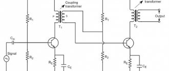
▍ Circuit with push-pull output stage
A power of 5 W may not be enough for a radio amplifier. It is proposed to increase the output power by replacing the single-cycle output stage (SE) with a push-pull (PP). To do this, the output stage is excluded from the original circuit, and one of the circuits given below is connected instead:
The circuit has become much more complicated: instead of one stage on one lamp, there are now two stages on three lamps.
A phase inverter circuit is assembled on lamp L1, converting the input analog signal into two antiphase output signals. A signal with a phase of 0° is supplied to the “upper arm” of the output push-pull stage, and a signal with a phase of 180° is supplied to the “lower arm”.
The output stage now has two 6P3S lamps. The stated output power of the amplifier is 15-20 W. In theory, adding a second 5 W lamp to the output stage would increase the amplifier power by these 5 W, i.e. twice. We'll look into why the output power has increased three to four times later.
The design of the output transformer has changed: the cross-section of the magnetic core has increased to increase the overall power, and the primary winding has a tap from the middle.
The anodes of the output lamps are connected to the outer terminals of the primary winding, the anode voltage source is connected to the middle point. The halves of the primary winding are connected in such a way that antiphase currents in the halves of the primary winding cause currents in the same direction in the secondary winding of the output transformer. Accordingly, the common-mode anode currents in the secondary winding are subtracted from each other.
The value of the cathode resistor in the diagram is 220 Ohms. In terms of direct current, the lamps in a push-pull cascade are connected in parallel; accordingly, a significantly larger current flows through this resistor than would flow through a cathode resistor of the same rating in a single-cycle circuit, therefore, the bias voltage module on the control grids of the push-pull cascade under consideration will be greater.