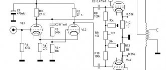
The amplifier is made on 6G2 lamps, which serves as a voltage amplifier (driver) for the final stage lamp - 2A3 with direct connection of the 2A3 grid to the 6G2 anode circuit. The non-working legs of the 6G2 lamp are connected to the body. To maintain the operating mode of the 2A3 output lamp, the power supply of the 6G2 lamp is made symmetrical relative to the cathode of the output lamp with a “virtual ground”; resistor R7 serves to adjust the quiescent current of the output stage to 60 mA, which is determined by a voltage drop of 0.06 V across resistor R6. The preliminary setup is done as follows: The output lamp grid is disconnected from the driver anode and connected to a 1 Ohm cathode resistor. At the anode of the driver lamp, the voltage is set to -50-55V relative to point B (the midpoint of the anode winding of the power transformer). Then the output lamp grid is connected to the driver anode and the final adjustment is made to the output lamp anode current, which should be about 60 mA with a voltage drop of 0.06 V across a 1 Ohm resistor R6. The D311 diodes in the filament-cathode circuit of the 2A3 lamp can be replaced with 10 Ohm resistors. Electrolytic capacitors 200uF are designed for an operating voltage of 400V, C2 for an operating voltage of 10V.
The power supply circuit is made on a 5Ts3S or 5Ts4S kenotron, which serves to rectify the positive voltage, and a 6X2P double diode, which rectifies the negative voltage to power the 6G2 driver lamp. Turning on the anode power with a toggle switch in the kenotron filament circuit after five minutes of warming up the lamps.
The amplifier can be easily adjusted using serviceable lamps and parts. Moreover, it is highly desirable to use parts of the highest quality. I do not consciously write down what details I have used, giving me the opportunity to independently select components based on sound. Despite the apparent simplicity of the circuit, the amplifier has good sound. Amplifier sensitivity - 0.7V, output power - 2.8 W with THD up to 1.5-2%.
The power transformer is made on iron Ш30х50. The output transformers are made of ShLM 32x50 iron, the anode winding has 2502 turns in three sections of 834, wire 0.25, the secondary winding for a 4 Ohm load consists of 4 sections of 100 turns of wire 0.71, the first section of the secondary winding is divided in half for connection load 8 ohms. When connecting all four sections in parallel and in series, two at a time, it is possible to connect a 16 Ohm load. Non-magnetic gasket in the gap of output transformers is 0.12 mm.
The amplifier is designed to be built by amateurs who have some experience in building and tuning tube designs.
Good luck!
P.S. the schematic diagram was made by Evgeny Razumov.
Tube push-pull final transmitter amplifier
Manankov E., Voronezh
“Practical advice - do not consider the parameters of the amplifier as immutable, and its circuitry as inviolable.”
R. A. Svoren
Sports transceiver equipment is usually made using semiconductor devices. Design using radio tubes is used when the parameters of a tube device are considered better by the consumer than a semiconductor device. For this reason, to this day, audio equipment designs are being developed where radio tubes, in addition to their direct purpose, are used as a decorative element included in the design of the structure.
Most shortwave radio athletes still include a tube amplifier with a power of more than 100 W in their radio transmitting equipment. This is due to the fact that such high-power amplifiers have proven themselves to be more reliable, easier to manufacture and stable in operation.
Amplifiers with a power of 200 W or more are designed using a single-cycle circuit, often connecting tubes in parallel to obtain the required power, and less often symmetrical tube push-pull amplifiers are built.
A single-cycle amplifier circuit is simpler than a push-pull one: it is easier to coordinate with asymmetrical circuits at the input and output, and only one amplification element is used in the amplifier design. However, the presence of even harmonics and the most powerful second harmonic in the output signal does not give the right to say that this is the best amplifier option. The power of the power source is wasted on the second harmonic, released in the form of heat in the output selective circuits, and in addition, there is a possibility of the second harmonic of the signal appearing in the load (antenna). The very first harmonic tends to get into the power supply line, creating interference with household equipment. Therefore, careful protection of both the signal and power supply circuits is required from unnecessary interference in these circuits.
In a push-pull amplifier circuit, these shortcomings, which affect the quality of the signal, are much less pronounced, but all this requires the presence of two amplification elements, input and output balancing when working with asymmetrical loads and asymmetrical outputs of signal sources. However, the advantages and disadvantages of single-ended and push-pull amplifier circuits are well described in educational literature on radio engineering.
The push-pull circuit of a short-wave amplifier can be implemented in its classic form for one narrow section of the HF range, but in order to expand the bandwidth of the amplifier, one has to face the problem of switching input and output selective circuits, with the difficulty of quickly setting up these circuits.
Many homemade designers are still trying to solve these problems and build a broadband push-pull tube amplifier, simple and easy to control, similar in circuit design to a transistor amplifier. An example of this is the publication in Radio magazine No. 11, 1987, pp. 58-60. In the article by S. Kozakov (RW3DF) “Designers of communication equipment report,” V. Krylov (RV3AW) proposed a circuit of a broadband push-pull amplifier with a power of 130 W using 6P42S lamps at an anode voltage of 300 V.
Then a similar circuit of a push-pull power amplifier with common grids on GU50 lamps (anode voltage 600 V) appeared by V. Kulagin (RA6LFQ) in the magazine “Radio Amateur” No. 10 for 1995, article “Power Amplifiers”, pages 29-30.
In the book “Designs and circuits for reading with a soldering iron”, issue 7, Solon-R, Moscow, 2001, (pp. 244-247) in the article “Amplifier with transformerless power supply on a GU29 lamp” (anode voltage 600 V) proposed circuit of a push-pull tube broadband amplifier created by I. Avgustovsky.
In the magazine “Radio Amateur KB and VHF” No. 2 for 2003 on page 36 in the article “HF Power Amplifiers” two more circuits of tube push-pull silos are proposed, one with a common cathode on four 6P45S lamps, the other with a common grid on four GU50.
All these schemes, having slight differences, are essentially the same thing. It makes no sense to consider them broadband with a range of 3.0...30.0 MHz with the advantages of a push-pull amplifier, and when you try to implement them, nothing worthwhile comes of it. It seems that the above-mentioned authors could not help but see that something was wrong in these circuits when operating at a normalized load of 50 (75) Ohms and, probably, simply brushed it aside - no one would do this anyway, or they had other reasons.
However, the use of multi-band omnidirectional harmonic antennas of the “Ground Plane” type, which create strong spurious radiation, again and again forced us to understand the reasons for the inoperability of the above-mentioned push-pull amplifier circuits.
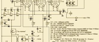
All of these listed amplifier options have been tested, and the result is the same – negative. Through endless trial and error, it became clear what is needed for a tube push-pull broadband amplifier to work. It turned out not so much - see fig. 3.1. As a result, it became possible to produce a compact, reliable, fairly powerful, light-weight broadband amplifier (WBA).
The proposed options had to be abandoned, because these amplifiers refused to amplify signals with a wavelength shorter than 40 meters and, moreover, proved to be “dirty”, especially in the low-frequency part of the HF range.
The mixed inductive-capacitive coupling of the output broadband transformer (WBT) with the P-circuit at high frequencies does not make it physically possible to implement the P-circuit with an active 50-ohm amplifier load. Even the use of high-frequency ferrite cores in transformers does not provide the required coupling value, which at high frequencies
although it increases, it does not increase to a sufficient extent (in parallel with the equivalent resistance characterizing the inductive coupling, a capacitive one is also connected at higher frequencies). The amount of coupling at low frequencies is large, but at high frequencies it is too small. All this is inherent in the very design of the proposed transformers.
The output transformer with uncontrolled coupling in these circuits is the main reason for the inoperability of the silo, since at low frequencies for normal operation of the amplifier, a strong coupling of the anode circuit of the lamps with the load is not needed, whereas at high frequencies the coupling must be increased.
Unsolved issues of balancing the amplifier at the input and output preserve the problems of a single-ended amplifier. In addition, the radio tubes used must meet certain requirements.
In push-pull tube silos it is necessary to use current radio tubes with high emission capabilities of the cathode and a satisfactory efficiency at a reduced anode voltage. All this is necessary to ensure that the equivalent resistance of the output stage of the amplifier is as small as possible, since the anodes of the lamps have to be loaded onto a transformer with low characteristic impedance, and a push-pull amplifier has an output equivalent resistance
lamps under the same conditions (with the same number of lamps) is 4 times more than that of a single-cycle.
The most suitable lamps for this purpose are 6P36S, 6P42S, 6IT44C, 6P45S lamps, used in TV scanners, or corresponding metal-ceramic radio tubes.
The output transformer type ShPT with inductive coupling was replaced by ShPTL with autotransformer coupling. In SHPTL it is easier to make branches to obtain optimal connection of the lamp anodes with the load, and it is possible to use a smaller core with a large initial magnetic permeability.
The working design of the amplifier was made using 6P45S lamps according to a common cathode circuit, as a “heavier” (due to the large capacitance of the control grid-cathode) version of the silo to obtain an output power of at least 200 W at a 50 Ohm active load.
The proposed bridge silo is intended for coupling with a transceiver, the power amplifier of which is made according to a single-cycle or push-pull circuit with a power of 20...30 W (10... 15 W per lamp).
The transceiver amplifier can be tube or semiconductor with an output impedance of 50 Ohms, the output is unbalanced and with the maximum permissible nonlinear distortion allowed for such power. Getting to the input of the circuit, nonlinear distortions at the output will increase. To suppress them, the input of the tube silo is organized accordingly.
The signal from the transceiver is fed to a “Binoculars” type wideband transformer (WBT) with low leakage inductance. The secondary winding of the SHPT increases the output voltage to twice the input voltage, and it is supplied symmetrically to the Wheatstone AC input bridge circuit.
Such a bridge, consisting of two active identical resistances and two equal reactive capacitive ones, is a special case of alternating current bridges. The balance of this bridge does not depend on the frequencies of odd harmonics of the signal, while for even harmonics it is unbalanced (the bridge is considered unbalanced when current appears in its short-circuited diagonal).
The AC bridge in this silo design is used as if instead of an input low-pass filter and, together with the P-circuit of the transceiver output amplifier, reduces nonlinear distortion of the signal supplied to the lamp grids of the bridge silo
This AC bridge of the bridge silo is formed as follows. In the arms of the bridge there are respectively active load resistances of the secondary winding of the input transformer
flashing, signaling that the amplifier is ready. After all, this anode voltage rectifier will be completely connected to the 220 V network.
Toggle switch SA2.1 allows you to switch the filament voltage of the lamps from 9 V to 12.6 V at the operator’s discretion, and, accordingly, supply a voltage of +300 V with contact SA2.2 to the screen voltage stabilizer +150 V (180 V).
Electric relay K1 in the time relay unit - RES64B, passport RS4.568.726-01. K2 – any for an operating voltage of 12 V with the appropriate groups of contacts.
Transistor VT1, in the screen voltage stabilizer, is a powerful high-voltage BU508A (the KT812, KT704 devices are inconvenient to mount and, moreover, they often fail).
The T1 transformer of the block is wound with a double wire from the network cable to the filling on an alsiferous or ferrite ring. In this design, the Alsifer ring is made up of two rings with a total dimension of K44x28x21 mm.
Fuses FU1 and FU2 are 3 A.
Tweet Like
- Previous post: Cell phone in burglar alarm
- Next entry: 27 – 28 MHz RANGE RECEIVER ON K174 SERIES CHIPS
- Common Emitter/Common Source Amplifiers (0)
- Amplifier classification (0)
- Push-pull amplifiers (0)
- Darlington circuit principle of operation (1)
- Simple differential amplifiers using transistors (0)
- Chroma off signal amplifier (0)
- Color bandpass amplifier (0)
Related posts:
Manakov tube tone block circuit diagram
The timbre block (see Fig. 1) is designed for connection to any tube final amplifier having a sensitivity of up to 1 - 1.5 V and an input impedance of 47 kOhm; when using amplifiers with a lower input impedance (volume control), the output capacitance should be increased capacitor C7.
Rice. 1. Tone block diagram.
Since modern sources (CD player, sound card) have low output impedance, a matching stage (cathode follower) is not needed; the signal from the source is fed directly to the tone control.
To compensate for signal attenuation in timbre-forming circuits, an amplification stage is used on a 6N3P or 6N23P lamp; those with 6N1P lamps can also use them without any alterations in the circuit, just take into account that their gain is lower.
The tone control range is +15.16 dB and -15.16 dB for bass and treble.
The output resistance with a 6N1P lamp is about 6 kOhm, 6N3P about 4 kOhm, with a 6N23P lamp about 2.5 kOhm.
Details: MLT resistors, capacitors K77, K78, shunt in power supply - K73, electrolytic in power supply - K50-32, you can use K50-7, or any other, capacitor in the cathode - tantalum, they have the best parameters and sound at polarizing voltage, than aluminum ones.
Use dual variable resistors for 2 channels with characteristic “A”, they are the most common, although with characteristic “B” there will be a smoother tone control.
Author: Anatoly Manakov (detector(s-ka)surguttel.ru)
Radio tubes used in the article:
|
You may be interested in:
Comments on the article:
| Added by: Vitaly |
| The scheme is not bad, it has its own nuances. For the simple class of music lovers. On professional amplifiers the sound quality is poor. |
| Date: 2019-05-13 |
| Added by: Vovan |
| For acceptable bends in the frequency response, the values of the capacitors in the circuit should be selected |
| Date: 2017-06-05 |
| Added by: Vovan |
| Efficient! — NOT RECOMMENDED FOR THE BRAINLESS! |
| Date: 2016-10-11 |
| Posted by: Dan |
| I assembled the circuit and it works! The replacements installed dual type SP-3 at 200 kOhm. |
| Date: 2016-08-18 |
| Added by: Victor |
| The author recommends installing variables with characteristic “B”. This is a logarithmic relationship. However, as far as I know, in audio equipment it is necessary to use inverse logarithmic variables, i.e. “B” or “A” in imported. Which ones are more correct to put here? I'm somehow confused. |
| Date: 2016-08-08 |
| Added by: ferdinand |
| the scheme works. but are there any tricks?? |
| Date: 2016-06-09 |
| Added by: ferdinand |
| I repeated this circuit. The circuit works. Thank you. 05/20/16 |
| Date: 2016-05-20 |
| Added by: Pasha |
| Guys, place this tone block after the final stage and from it to A.S. Works well. |
| Date: 2016-04-12 |
| Added by: abv27 |
| good scheme. |
| Date: 2015-01-09 |
| Added by: black |
| What voltage should be applied to the anode? |
| Date: 2014-08-15 |
| Added by: Alexander |
| The scheme is disgusting, the depth of adjustment is very small, there is no low end, there is a lot of highs, the lower middle is generally crazy |
| Date: 2014-01-15 |
| Added by: Nikolay |
| It would be nice to include it in the pre-amplifier |
| Date: 2013-03-13 |
| Added by: Alexander |
| When replacing the lamp with 6N1P and 6N8S, you need to increase the supply voltage to 350V |
| Date: 2012-05-01 |
| Added by: Evgeniy |
| Is it possible to use 6N9S, 6N8S lamps in this circuit? |
| Date: 2010-12-14 |
| Added by: Mikhail |
| The anode voltage here is 250V. |
| Date: 2010-11-16 |
| Added by: Roma |
| same question |
| Date: 2010-09-18 |
| Added by: Alexander |
| To repeat this circuit, I would like to know the value of voltage A and how the VL1 triodes are connected - for each channel or paralleled. |
When reprinting materials, a link to the original source is required.
Circuit diagram of a homemade stereo low-frequency power amplifier, assembled using a 6N23P tube and two 6P14P tubes. Foreign analogues of these lamps are ECC88 and EL84. The proposed tube ULF has the following characteristics: Reproducible frequency range - from 20Hz to 80kHz; Output power in triode mode - 2 x 2.75 W; Output power in pentode mode is 2 x 4.5 W.
Good afternoon, dear radio amateurs. As you know, history develops in a spiral, and the history of the development of audio technology is no exception to this. If you look at the playback amplifier market, you will notice that in the last few years there has been a reincarnation of tube amplifiers, and some manufacturers have resumed production of radio tubes. Today we would like to offer you the design of a simple tube amplifier designed.
The article describes the design of a single-stage low-power tube UMZCH, used by the author in conjunction with speakers built on the basis of high-sensitivity broadband heads. The amplifier uses parallel connection of two 6P9 pentodes, characterized by high gain. This made it possible to obtain an output power of up to 4 W when working with a signal source providing a signal voltage of up to 1.5. 2 V, i.e. from any CD player or smartphone.
This article is intended for vinyl lovers who have at least basic knowledge of radio engineering and know how to hold a soldering iron in their hands. Despite the abundance of digital audio sources, many of us still have a large collection of vinyl records. Moreover, the sound quality is decently recorded.
Schematic diagram of a homemade tube power amplifier for 6N8S and 6P3S, which uses factory transformers of the TPP-258-127/220-50 type. The author tells how he made the amplifier and what changes he made to the UMZCH circuit; photos of the disassembled and finished device are also provided.
The push-pull output stage of the stereo amplifier is distinguished by the use of a common current generator on the microcircuit in the cathode circuit, thanks to which paraphase control of the 6P14P pentodes is ensured. By choosing the transformation ratio of the load resistance, you can change to some extent.
The AF power amplifier, the circuit of which is shown in the figure, is made using lamps from old black-and-white TVs or radios. This is a pre-amplifier with a bass reflex on a 6N2P double triode and a push-pull output stage on two 6P14P tubes. The use of such old components is common.
To all connoisseurs of tube sound, I present to you my design of a tube semiconductor amplifier. The source for creativity was the deposits of germanium transistors that had been lying in a box and successfully forgotten for a good ten years. Probably few people know the fact that it is germanium that gives the sound as close as possible to tube sound.
I propose a well-developed UHF circuit for 6p45s, with a five-band tone block. The amplifier is made according to a classic single-ended circuit. The circuit of A. Manakov was taken as the basis. The diagram does not need a description of the operation. During the assembly and commissioning process, some resistor values were changed during the process.
How the idea to build a tube headphone amplifier came about The idea of building a high-quality tube headphone amplifier has been in my head for a long time. The idea is not bad, but one thing stopped me. From the technical side, assembling this product was not difficult. Many were reviewed.
- Price: 3600 rubles + delivery 400 rubles.
- Go to the store
Background:
While building a home audio system, I encountered difficulties. One of them is that my Musical Paradise MP-301 MK3 tube power amplifier, when connected “directly” to a source, gives a boring, compressed sound. Without “tops” and “bottoms”, just a protruding lower middle. Moreover, the film sound is good, but my music (black metal) plays poorly.
Obviously, loudness compensation is required. Buying a loud-compensation preamplifier board generally solved the problem, but the sound quality (in general) deteriorated. The preamp went to the mezzanine to gather dust.
I decided to use a tone block in my system instead of loudness compensation. There are Chinese ones already assembled, for example this one, on two 6n1p and a kenotron:
But I took it in Russia, from the site www.matyushin.com
, this set is a tube tone block preamplifier based on a 6n2p-ev double triode.
For 4000 rubles I received (all parts are new):
1100+1100 rubles - Two sets of parts for assembling two mono channels. 1000 rubles - TAN 15-01, toroidal power anode-heat transformer. 130 rubles - Power supply board. 270 rubles - Choke D15N (50mA, 10H). 400 rubles - shipping (from St. Petersburg to Novosibirsk).
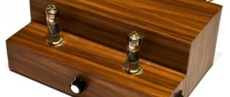
Parcel contents:
Close-up of the power supply components:
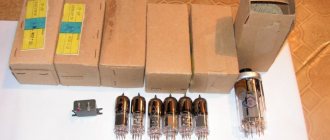
A choke, and two double triodes 6n2p-ev - produced in 1972 and 1976 - which is strange. I thought they would be one year old. And these are structurally different even to the eye:
(PS
: The author wrote that all his lamps are from 1976. My 1972 got into his kit in some unknown way, and he didn’t put it in my car on purpose. I suggested listening to this for now. Didn't offer free lamp replacement. He did not apologize for the missing radio components. In general, the seller does not use any polite words (“thank you,” “hello,” “goodbye”) in correspondence, probably for reasons of principle).
Preamp boards, two mono channels:
Set of parts No. 1:
Set of parts No. 2:
“Manuscript” (Xerox copy in A4) with handwritten marks that I could not fully decipher. Just evaluate the level of performance:
Almost soldered boards (the differences from the original photo on the website are immediately visible - coupling capacitors and lamp sockets):
The amplifier was assembled on a breadboard (I apologize for the quality of the photos):
Sound quality:
But the tone block, it seemed to me, was not quite optimally designed for high-quality speaker systems. A little “narrow” or something.
According to the author:
Adjustment within: ±8dB. LF: 300 Hz. HF: 3 kHz.
band: 20-20000Hz. (±0.3dB). THD: 0.05%. out: 2V、maximum 20V or more.
Because of this, the adjustment occurs in a limited range, which is clearly audible.
I would like bass adjustment: 100 Hz
and
HF: 10 kHz
, and maybe even wider. The seller said that the tone block circuit was designed by Manakov, and suits many.
For low frequencies, he suggested replacing capacitors C3, replacing the original 15 nF with 10 nF, like Manakov’s.
For high frequencies, I suggested changing the 1 nF capacitor C1 (according to Manakov’s scheme, C2 by Matyushin) downward.
You need two mono channels for the stereo option, which increases the inconvenience of adjustment, and twice the number of “twists”.
The instructions could have been more accurate.
The most common variable resistors are used, with characteristic “B”, so the timbres are not adjusted smoothly, but sharply, abruptly.
Complete radio components in the kit are the cheapest.
The kit was missing 4 resistors. The radio tubes were not paired.
There is no assembly diagram, so I could not assemble it correctly until I myself found an error in the markings applied to the board.
It turned out to be the exit block at the rear. It has reverse polarity compared to other pads on the board:
In general, the scheme proposed by Matyushin is less successful than Manakov’s scheme.
Manakov’s circuit is much simpler, the gain is less (which is good), since Matyushin’s is redundant.
In addition, Matyushin’s circuit requires three expensive coupling capacitors per channel, instead of Manakov’s one.
PS
I decided to make a Manakov tone block from Matyushin’s tone block. According to the scheme, we remove the following elements:
We get this type of board:
The biggest influence on the sound quality of this preamplifier is the coupling capacitor and capacitor C2 in the tone block. I installed paper-oil K40U-2 (0.1 µF 350V) instead of film Wima, because I couldn’t find anything more suitable. On C2 you need to put either high-voltage ceramic or mica. I installed SGM-1.
The sound quality has increased greatly compared to the original circuit, but the K40U-2 capacitor begins to sound good only after it has “warmed up” (at least half an hour). I don’t know what caused this, but it’s a fact.
P.P.S.
K40U-2 was replaced with a polypropylene Taiwanese Suntan 1uF 250V:
The sound has changed compared to the K40U-2 - on my black metal, the “middle” has become more dynamic and harsh. But at the same time, the sound became less “singing” and “soulful” on rock ballads, etc.
PPPS
A 6N2P-EV lamp can be replaced with a 6N1P-EV lamp without changing the circuit - just pulled out one and inserted another (as you can see, I also bypassed the electrolytes in the anodes with 1uF 250V film capacitors, I didn’t hear a difference, but let them be):
The only difference I heard is that the 6N1P-EV plays a little quieter. Well, inside they are different in design:
PPPPS
As a result of my barbaric, random experiments, one of the two 6N2P-EV lamps fell victim. Interestingly, the newer lamp, from 1976, burned out.