If you have some idea and for it you need a sound generator, either a signal of a given shape and frequency, or one of the types of noise, then the simplest, fastest and most flexible way to solve this problem can be to use the free multi-platform audio editor Audacity.
This audio editor has very broad capabilities and will more than satisfy the needs of the vast majority of users in terms of processing audio files, for example, to highlight voices and improve the quality of voice recordings (there is also a download link). And of course, the fact that the program is absolutely free and works both in Microsoft Windows and Linux and even on Mac OS X cannot but rejoice. For this reason, it is offered for use by everyone - it is a worthy representative of open source.
This is what the program window looks like after opening.
Sound generation
Audacity allows you to generate basic waveforms, noise types, and waveform packets.
Signal generation options are hidden in the Create
The three lowest lines will not be considered in this article, because are responsible for creating metronome clicks and drum sounds. It also has its own interesting things and you can get a variety of sounds. But more on that another time, but for now let’s look at the main types of generation.
Silence or Create silence
Not to say that this can be called signal generation, because... This is the generation of no signal. An empty audio track of the selected duration is created. If you select part of a track, the duration of the piece will be automatically entered.
This is convenient when processing real recordings, when you need to mute some part. There is even a special button in the toolbar for quick access to this function. When you press it, the window will not come out, and the selected piece will be immediately muted.
The button to the left allows you to do the opposite, i.e. leave only the selected piece and remove what is around it.
Tone…
A button that opens the menu for generating tone signals - i.e. signals whose frequency, shape and amplitude are constant throughout their entire duration. This may be needed, for example, to add obscenities to a recording .
At the top there is a drop-down list asking you to select a signal shape. Among the common options, only the triangular shape is missing.
The frequency is set in the Frequency(Hz) and can range from 1 to 22050 Hertz. Fractional values are also supported. As the name suggests, the Amplitude specifies the amplitude, that is, the range of the signal. Well, the Duration is already familiar.
It is worth noting that there are two types of meander (quadratic wave) - one ordinary, the second unusual
no smoothing. At the same time, a meander without smoothing is much smoother and less similar to a meander than a regular one. Apparently translation errors.
The picture shows all four available waveforms generated for a frequency of 1kHz and amplitude = 1 (0 dB)
Radio amateur
SoundCard Oszilloscope - a program that turns your computer into a two-channel oscilloscope, a two-channel low-frequency generator and a spectrum analyzer
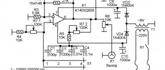
Good afternoon, dear radio amateurs! Every radio amateur knows that to create more or less complex amateur radio devices, you need to have at your disposal not only a multimeter. Today in our stores you can buy almost any device, but - there is one “but” - the cost of a decent quality device is no less than several tens of thousands of our rubles, and it is no secret that for most Russians this is a significant amount of money, and therefore these devices are not available at all, or a radio amateur buys devices that have been in use for a long time. Today on the Radio Amateur website, we will try to equip the amateur radio laboratory with free virtual instruments - a digital two-channel oscilloscope , a two-channel audio frequency generator , a spectrum analyzer . The only drawback of these devices is that they all operate only in the frequency band from 1 Hz to 20,000 Hz. The site has already given a description of a similar amateur radio program: “Digital Oscilloscope“ - a program that turns a home computer into an oscilloscope. Today I want to bring to your attention another program - “ SoundCard Oszilloscope ”. I was attracted to this program by its good characteristics, thoughtful design, ease of learning and working in it. This program is in English, there is no Russian translation. But I don't consider this a disadvantage. Firstly, it’s very easy to figure out how to work in the program, you will see it yourself, and secondly, someday you will acquire good devices (and they have all the symbols in English, although they themselves are Chinese) and you will immediately and easily get used to them.
The program was developed by C. Zeitnitz and is free, but only for private use. A license for the program costs about 1,500 rubles, and there is also a so-called “private license” - costing about 400 rubles, but this is more of a donation to the author for further improvement of the program. Naturally, we will use the free version of the program, which differs only in that when you launch it, a window appears each time asking you to buy a license.
Download the program (latest version as of December 2012):
Computer - oscilloscope, generator, spectrum analyzer (28.1 MiB, 64,658 hits)
First, let's understand the “concepts”: An oscilloscope is a device designed for research, observation, and measurement of amplitude and time intervals. Oscilloscopes are classified: ♦ by purpose and method of outputting information: – oscilloscopes with periodic scanning for observing signals on the screen (in the West they are called oscilloscop) – oscilloscopes with continuous scanning for recording the signal curve on a photographic tape (in the West they are called oscillograph) ♦ by the method of processing the input signal: – analogue – digital
The program works in an environment no lower than W2000 and includes: - a two-channel oscilloscope with a bandwidth (depending on the sound card) of at least 20 to 20,000 Hz; – two-channel signal generator (with a similar generated frequency); – spectrum analyzer – and also has the ability to record an audio signal for subsequent study
Each of these programs has additional features that we will look at as we explore them.
We'll start with the signal generator:
The signal generator, as I already said, is two-channel - Channel 1 and Channel 2. Let's consider the purpose of its main switches and windows: 1 - buttons for turning on the generators; 2 – window for setting the output signal shape: sine – sinusoidal triangle – triangular square – rectangular sawtooth – sawtooth white noise – white noise 3 – output signal amplitude regulators (maximum – 1 volt); 4 – frequency control knobs (the desired frequency can be set manually in the windows under the knobs). Although the maximum frequency on the regulators is 10 kHz, you can enter any allowed frequency in the lower windows (depending on the sound card); 5 – windows for setting the frequency manually; 6 – enable the “Sweep – generator” mode. In this mode, the output frequency of the generator periodically changes from the minimum value set in the “5” boxes to the maximum value set in the “Fend” boxes during the time set in the “Time” boxes. This mode can be enabled either for any one channel or for two channels at once; 7 – windows for setting the final frequency and time of Sweep mode; 8 – software connection of the generator channel output to the first or second input channel of the oscilloscope; 9 — setting the phase difference between the signals from the first and second channels of the generator. 10 — setting the signal duty cycle (valid only for a rectangular signal).
Now let's look at the oscilloscope itself:
1 – Amplitude – adjustment of the sensitivity of the vertical deflection channel 2 – Sync – allows (by checking or unchecking) separate or simultaneous adjustment of two channels according to signal amplitude 3, 4 – allows you to separate signals along the height of the screen for their individual observation 5 – setting the sweep time (from 1 millisecond to 10 seconds, with 1000 milliseconds in 1 second) 6 – start/stop the oscilloscope. When stopped, the current state of the signals is saved on the screen, and a Save button ( 16 ) appears, allowing you to save the current state on the computer in the form of 3 files (text data of the signal under study, a black-and-white image and a color image of the picture from the oscilloscope screen at the time of stop) 7 – Trigger – a software device that delays the start of the sweep until certain conditions are met and serves to obtain a stable image on the oscilloscope screen. There are 4 modes: – on/off . When the trigger is turned off, the image on the screen will look “running” or even “smeared”. - auto mode . The program itself selects the mode (normal or single). – normal mode . In this mode, a continuous sweep of the signal under study is carried out. – single mode . In this mode, a one-time sweep of the signal is carried out (with a time interval set by the Time regulator). 8 – selection of the active channel 9 – Edge – type of signal trigger: – rising – along the edge of the signal being studied – falling – along the decline of the signal being studied 10 – Auto Set – automatic setting of the sweep time, the sensitivity of the vertical deviation channel Amplitude, and also the image is driven to center of the screen. 11 — Channel Mode – determines how signals will be displayed on the oscilloscope screen: – single – separate output of two signals on the screen – CH1 + CH2 – output of the sum of two signals – CH1 – CH2 – output of the difference of two signals – CH1 * CH2 – output of the product of two signals 12 and 13 – selection of display of channels on the screen (or any of the two, or two at once, the Amplitude ) 14 – output of the oscillogram of channel 1 15 – output of the oscillogram of channel 2 16 – already passed – recording the signal to the computer in the oscilloscope stop mode 17 – time scale (our Time is set to 10 milliseconds, so the scale is displayed from 0 to 10 milliseconds) 18 – Status – shows the current state of the trigger and also allows you to display the following data: – HZ and Volts – display the current frequency voltage of the signal under study – cursor – enable vertical and horizontal cursors to measure the parameters of the signal under study – log to Fille – second-by-second recording of the parameters of the signal under study.
Taking measurements on an oscilloscope
First, let's set up the signal generator:
1. Turn on channel 1 and channel 2 (green triangles light up) 2. Set the output signals - sinusoidal and square 3. Set the amplitude of the output signals to 0.5 (the generator generates signals with a maximum amplitude of 1 volt, and 0.5 will mean the amplitude of the signals equal to 0.5 volts) 4. Set the frequency to 50 Hertz 5. Switch to oscilloscope mode
Measuring signal amplitude:
1. Using the button under the inscription Measure , select the mode HZ and Volts , check the boxes next to the inscriptions Frequency and Voltage . At the same time, we have on top the current frequencies for each of the two signals (almost 50 hertz), the amplitude of the total signal Vp-p and the effective voltage of the signals Veff . 2. Using the button under the Measure , select the Cursors and check the Voltage . In this case, we have two horizontal lines, and at the bottom there are inscriptions showing the amplitude of the positive and negative components of the signal ( A ), as well as the overall range of the signal amplitude ( dA ). 3. We set the horizontal lines in the position we need relative to the signal, on the screen we will receive data on their amplitude:
Measuring time intervals:
We perform the same operations as for measuring the amplitude of signals, with the exception of – in the Cursors , we put a tick next to the Time . As a result, instead of horizontal ones, we will get two vertical lines, and at the bottom the time interval between the two vertical lines and the current frequency of the signal in this time interval will be displayed:
Determining signal frequency and amplitude
In our case, there is no need to specifically calculate the frequency and amplitude of the signal - everything is displayed on the oscilloscope screen. But if you have to use an analog oscilloscope for the first time in your life and you don’t know how to determine the frequency and amplitude of a signal, we will consider this issue for educational purposes.
We leave the generator settings as they were, with the exception of setting the signal amplitude to 1.0, and setting the oscilloscope settings as in the picture:
We set the signal amplitude control to 100 millivolts, the sweep time control to 50 milliseconds, and we get a picture on the screen like above.
The principle of determining the signal amplitude: Our Amplitude regulator 100 millivolts , which means that the cost of dividing the grid vertically on the oscilloscope screen is 100 millivolts. We count the number of divisions from the bottom of the signal to the top (we get 10 divisions) and multiply by the price of one division - 10 * 100 = 1000 millivolts = 1 volt , which means that the amplitude of the signal from the top to the bottom is 1 volt. In exactly the same way, you can measure the signal amplitude in any part of the oscillogram.
Determining the timing characteristics of a signal: Our Time regulator 50 milliseconds . The number of horizontal divisions of the oscilloscope scale is 10 (in this case, we have 10 divisions on the screen), divide 50 by 10 and get 5, this means that the cost of one division will be equal to 5 milliseconds. We select the section of the signal oscillogram we need and count how many divisions it fits into (in our case, 4 divisions). We multiply the price of 1 division by the number of divisions 5*4=20 and determine that the signal period in the area under study is 20 milliseconds .
Determination of signal frequency. The frequency of the signal under study is determined by the usual formula. We know that one period of our signal is 20 milliseconds , it remains to find out how many periods there will be in one second - 1 second/20 milliseconds= 1000/20= 50 Hertz.
Spectrum analyzer
A spectrum analyzer is a device for observing and measuring the relative energy distribution of electrical (electromagnetic) oscillations in a frequency band. A low-frequency spectrum analyzer (as in our case) is designed to work in the audio frequency range and is used, for example, to determine the frequency response of various devices, when studying noise characteristics, and tuning various radio equipment. Specifically, we can determine the amplitude-frequency response of the audio amplifier being assembled, configure various filters, etc. There is nothing complicated in working with a spectrum analyzer; below I will give the purpose of its main settings, and you yourself, through experience, will easily figure out how to work with it.
This is what the spectrum analyzer looks like in our program:
What's here - what:
1. Type of display of the analyzer scale vertically 2. Selection of displayed channels from the frequency generator and type of display 3. Working part of the analyzer 4. Button for recording the current state of the oscillogram when stopped 5. Mode of increasing the working field 6. Switching the horizontal scale (frequency scale) from linear in logarithmic form 7. Current signal frequency when the generator is operating in sweep mode 8. Current frequency at the cursor position 9. Signal harmonic distortion index 10. Setting a filter for signals by frequency
View Lissajous figures
Lissajous figures are closed trajectories drawn by a point that simultaneously performs two harmonic oscillations in two mutually perpendicular directions. The appearance of the figures depends on the relationship between the periods (frequencies), phases and amplitudes of both oscillations.
X ” and “ Y inputs of the oscilloscope, you can see Lissajous figures on the screen. This method is widely used to compare the frequencies of two signal sources and to match one source to the frequency of the other. When the frequencies are close, but not equal to each other, the figure on the screen rotates, and the period of the rotation cycle is the reciprocal of the frequency difference, for example, the rotation period is 2 s - the difference in the frequencies of the signals is 0.5 Hz. If the frequencies are equal, the figure freezes motionless, in any phase, but in practice, due to short-term instabilities of the signals, the figure on the oscilloscope screen usually trembles a little. You can use for comparison not only identical frequencies, but also those that are in a multiple ratio, for example, if the reference source can only produce a frequency of 5 MHz, and the tuned source can produce a frequency of 2.5 MHz.
I'm not sure that this function of the program will be useful to you, but if you suddenly need it, then I think that you can easily figure out this function on your own.
Audio recording function
I have already said that the program allows you to record any sound signal on a computer for the purpose of further study. The signal recording function is not difficult and you can easily figure out how to do it:
Type of files saved by the program on the computer in the mode of stopping and recording the current oscillogram:
We advise you to read: Connecting devices to a virtual oscilloscope and generator via a sound card
“Computer-oscilloscope” program
Chirp…
It is also possible to create signals whose frequency and/or amplitude continuously changes throughout their entire duration.
There are a little more input windows here, but they are all already familiar to us, with the exception of Interpolation
. There are two interpolation options available: linear and logarithmic. Interpolation determines how the frequency will change over time. For the parameters specified in the image, depending on the selected interpolation type, the following signals will be generated:
Library for controlling the frequency of a PWM signal in Arduino
You can download this library from the following link - Arduino PWM Frequency Library.
Using the provided link you will download the library as a ZIP file. After extracting the information from this ZIP file, you will get a directory (folder) named PWM. Go to the Arduino IDE libraries folder (for Windows operating system users this folder will be located at C:\Users\User\Documents\Arduino\libraries) and copy this PWM folder there. It is possible that you already have a folder named PWM in the Arduino IDE libraries - in this case, you need to replace it with a new (downloaded) folder.
DTMF Tones...
The abbreviation stands for D ual- T one
M ulti- F requency
, which can be translated into Russian as two-tone multiple signals.
Signals similar to those that sound when pressing keypad buttons on telephones are generated. In the Sequence we need to enter what we want to create similar signals for. And the Signal/Silence Ratio determines the duration of signals and pauses. In the case of 50%, the duration of the signal is equal to the duration of the pause.
For the entered parameters, 9 two-tone signals will be generated:
Required Components
- Arduino Nano board (buy on AliExpress).
- Incremental encoder with button (buy on AliExpress).
- OLED display 128x64 (buy on AliExpress - for this project you can buy a model with 4 contacts since it is connected via the I2C interface).
- Adafruit SI5351 CLOCK GEN (clock generator) (buy on AliExpress).
- Toggle Switch, SPDT (switch).
- Panasonic RCA JACK (RF output connector).
- Capacitors 10 nF and 100 nF (buy on AliExpress).
- Capacitor 10 uF (buy on AliExpress).
- 1 kOhm resistor (buy on AliExpress).
- Inductor 100 uH (Inductor 100 uH) (buy on AliExpress).