In this tutorial, you'll learn how to use the I2S communication protocol to transmit digital audio signals to record and visualize microphone data and play music from internal memory as well as from an external SD card.
We will also compare different microcontrollers and see why we prefer the ESP32 microcontroller for our I2S projects.
Why do we need the I2S protocol?
If we want to play a digital audio file using a microcontroller board, we have to consider the entire digital audio chain. The following schematic diagram shows how the audio file is saved on the SD card and read from the microcontroller board. The board is then connected to the speaker via a digital pin and ground.
In my case, I have a sample audio file with a sample rate of 44.1 kHz, stereo format and 16-bit audio depth. On our input side, where we want to read the music file, we have no problem because the SPI connection is fast enough that the quality does not degrade during transmission.
But from the output side we have to convert the digital signal to analog signal. This is done using a digital-to-analog converter (DAC). Depending on the microcontroller used, different problems arise:
- Arduino and ESP8266
: Arduino boards, as well as ESP8266 in general, do not have an internal DAC and therefore you will have to build the DAC with external components. - ESP32
: The ESP32 has an internal DAC to create an analog output signal, however the DAC only has 8-bit resolution. Since we have a 16-bit input signal, we will lose some quality.
But how can we convert digital data from a WAVE file to a speaker? The solution to this problem is the I2S communication protocol, which supports 4 to 32 bits of data per sample. To make our lives even easier, we use the MAX98357 I2S Audio Breakout Board. But first, we'll dive into the I2S communication protocol.
How I drove I2S using a regular Fast Ethernet CAT5 patch cord
The disappointment that washed over me was unexpected. How so? Despite the mass of enthusiasm for the method of transmitting information over this wonderful bus, about the increase in sound quality, and other positive aspects, there was not a single completed circuit solution at the “source housing” - “DAC housing” level.
And since my transport is a PC with USB output, the “case” - “case” solution is the best option. And quite high-quality USB transport solutions with I2S TTL output are increasingly appearing on the market. In general, you need to think over a link that allows you to drive I2S from the transport to the DAC in TTL format, and even with galvanic isolation. In general, for such purposes it would be technically correct to use an LVDS bus, but in addition to the obvious advantages in the form of a long transmission distance, symmetrical lines, we also have our disadvantages - the high cost and difficulty of obtaining transceiver chips, the need to use special connectors, and the lack of galvanic isolation.
I need a distance of more than half a meter, but how to organize this? A picture immediately appeared in my head: a bunch of shielded wires, a gold-plated connector. Oh yes! Connector! The search, as usual, yielded “a lot of options.” Someone used a DB-9 - a connector from the COM port of a PC. But my “personal dislike” for it as a connector did not allow me to settle on this decision.
What do foreigners use in their versions of USB transports? A short search and there is the answer - RG45. Eight-pin plastic crimp connector used in Fast Ethernet (100BASE-T) network infrastructure! Four isolated twisted pairs! “Great!” I said. “Aha!” said the search engine. “And the pinout?” - Come on, try it. “I2S pinout”, “RG45 I2S” and thirty-two more options. - No? - You don’t know how to search! And I really can’t. Since out of all the “factory” ones found, two options were interesting - Northstar DAC Model 192 MKII and Terralink X, it was decided to go with them.
Everything else found had something not quite right, including +5V phantom power. Well, I also couldn’t find information about the connecting cable used with these devices. Well, in general, the Terralink layout suited me, since it turned out that it coincided in pairs with the pinout of the standard patch cord.
I2S communication protocol
In this part of the I2S tutorial, we want to take a closer look at the I2S communication protocol. Therefore, we cover three important topics.
- 3-wire I2S connection
- I2S network components
- I2S timing diagram
The following table shows which boards have an I2S interface and which do not.
| Has an I2S interface | Does not have an I2S interface | |
| Arduino | Arduino boards Arduino Due, Arduino MKR Zero, Arduino MKR1000 WiFi | with ATmega328P microcontroller, such as Arduino Uno or Arduino Nano. |
| ESP | ESP8266 ESP32 |
From the table you can see that only some special Arduino boards have I2S interface, but not the most used boards such as Arduino Uno. Also, all ESP8266 and ESP32 boards support the I2S interface, so I recommend using an ESP8266 or ESP32 microcontroller based board for this tutorial. In my case I'm using an ESP32 microcontroller because the libraries we use support ESP32 better than ESP8266 in my experience.
I2S and the era of digital audio
The growing collection of common electrical engineering abbreviations can be a little overwhelming at times; and I wouldn't be surprised if you've seen the term "I2S" a few times and just assumed it was just a misspelling of the "I2C" acronym.
There is indeed some connection between these two protocols. Both were originally developed by Philips Semiconductors (now NXP), and both have names starting with "I2" because they are designed for inter-chip communication (abbreviated "IC"). However, I2S came after I2C, and while I2C is a universal interface, I2S is designed to carry audio data—the “S” in the name stands for “sound.”
I2S was created in the 1980s, when digital began its conquest of the consumer audio market. The stated purpose of I2S is to facilitate audio electronics development by providing a standardized interface for transmitting digital data between ADCs, DACs, digital filters, digital signal processors, and other types of integrated circuits used in audio systems. It is essentially a two-channel protocol because it was designed for stereo audio.
3-wire I2S connection
The I2S protocol uses three wires for communication.
Serial Clock (SCK)
, also called bit clock line (
BCLK
), are used to obtain all components in one cycle.
The serial clock frequency is defined as follows: Frequency = Sampling frequency * Number of bits per channel * Number of channels.
For my WAVE file that I'm using in this tutorial, we already know the following variables:
- Sampling frequency: 44.1 kHz
- Bits per channel: 16
- Number of channels: 2
Therefore, the serial clock frequency is 44.1 kHz * 16 * 2 = 1.411 MHz.
Second line of I2S communication protocol
- This is a
word selection wire (Word Select - WS)
or frame selection (
Frame Select - FS
), which distinguishes between the left or right channel.
- If WS = 0 → channel 1 (left channel) is used
- If WS = 1 → channel 2 (right channel) is used
Last wire
- This is
a serial data line (Serial Data - SD)
, along which the payload is transmitted with two's complement. It is important that the most significant bit is transmitted first (MSB first) because the transmitter and receiver may have different word lengths. Therefore, neither the transmitter nor the receiver needs to know how many bits are being transmitted. But what happens if the word length between the transmitter and receiver does not match?
- If receiver WS > transmitter WS → the word is truncated (the least significant data bits are set to 0)
- If receiver WS < transmitter WS → bits after LSB are ignored
Controller organization [ edit | edit code ]
The controller has two parts, as well as a block of external terminals. They are responsible for data transmitted and received over one conductor, as well as for clock and frame synchronization signals. The controller transmits them, managing the exchange process. For the device to work correctly, you cannot change the input with the output, because the opposite can lead to a digital loop.
The first part is the controller itself with inputs. To operate, it requires a clock generator that outputs direct access channel events. The reception and transmission of sound can be carried out not by a microprocessor, but by a direct access channel, a special processor for data input and output. This direct access channel requires events to start reading data from receive registers or transmitting data to transmit registers.
The second part is interface registers, the following types are provided:
- Interrupt flag registers;
- Interrupt enable register from one source or another (by the number of interrupt flags or by the number of bits of the interrupt enable register)
- A control register in which the controller operating modes are set;
- The sampling frequency generator register, in which you can set the clock signal and its frequency for bit synchronization - if data is received, the register writes this data and it can be calculated by software;
- Two data reception registers;
- Registers for data transmission over channels, in which there can be two 32-bit registers transmitted sequentially.
Interrupt signals indicate which events have occurred within the controller and need to be processed. There are two groups of interrupts: the first is interruptions associated with the reception and transmission of data and events, the second is associated with the processing and generation of clock signals. It generates signals for the direct access channel and the interrupt controller.
If the device is passive (plays the role of a slave), then the signals come from outside to the synchronizer. In one case, it receives and amplifies, reformats clock signals, turning them from smooth along the contour to clear and sharp. In another case, it provides a synchronization signal to an external device. The signals of the block responsible for enabling or disabling operation are generated based on the state of the bit in the control register.
The interrupt handler first reads the interrupt flag register to reset it later. Next reads or writes data to the I²S data registers if the direct access channel is not used. After this, the interrupt returns.
Configuration options set the polarity of bit and frame synchronization for the synchronizer. This data helps the synchronizer select the operating mode of the audio interface.
Receiving data [edit | edit code ]
The serial receiver clearly records the signal levels that are clocked by the synchronizer. Next, this data is fed bit by bit along the received data line into the shift register, which synchronizes the data from the synchronizer. After the shift register is stored, it is written into the receive register buffer. The size of the shift register is determined by the word length. After the register buffer registers received data, sign expansion may occur. Since the fixed-point format is obviously used, it is necessary to expand the sign to 32 bits, resulting in 12 bits of data. The most significant bit of the received data is propagated to all the most significant bits of the register so that there is a correct number represented in fractional format.
I2S network components
If there are multiple I2S components connected to each other, I call it an I2S network. The network components have different names as well as different functions. The following figure shows three different networks that I will describe.
In the first image we have a transmitter as well as a receiver. The transmitter can be an ESP NodeMCU board and the receiver can be an I2S audio jack board, which we describe in the next section. We also have three wires for connecting I2S devices.
In this first case, the transmitter is the master because the master controls the serial clock lines (SCK) and word selection lines (WS). In the second picture we see the opposite because the receiver of I2S messages can also be the master. Therefore, the SCK and WS lines start from the receiver and end at the transmitter.
The third figure shows that the external controller can also be a master device that generates SCK and WS. The controller is connected to nodes in the network.
All I2S networks have only one master device. There may be several other components that receive or transmit audio data.
Great, but which audio interface should I buy?
There are audio interfaces on the market to suit every budget, from under $100 to several thousand of your hard-earned money. Be realistic about what you plan to do audio-wise. Do you need eight I/O if you'll only be playing with your uke when two I/O would suffice? On the other hand, if you're confident that you'll be recording live sessions with your cajon/flute/guitar jam trio next year, then four inputs/outputs will give you room to grow.
Another factor to keep in mind is progression. Ports become obsolete, operating systems evolve, and technology improves device performance. Expect your audio interface to last about 5-7 years before incompatibility gremlins (firewire ports, anyone?) come knocking.
Determine what you need from an audio interface, set a budget, and do your research.
Happy recording!
I2S timing diagram
To better understand the behavior as well as functionality of the I2S communication protocol, we will take a look at the following I2S timing diagram.
On the timing diagram you can see all three lines: SCK, WS and SD. First we have our serial clock, which has a sample rate * bits per channel * number of channels. In our example, 1.411 MHz. The second channel is a word selection line that ranges from 1 for the right audio channel to 0 for the left channel.
From the serial data line, we can see that data is sent every clock cycle on the falling edge (red dotted line) → HIGH to LOW. For I2S communication it is also possible to send data when changing from LOW to HIGH.
We also see that the WS line changes one clock cycle before the most significant bit (MSB) is transmitted. This gives the receiver time to store the previous word and clear the input register for the next word. The MSB is sent when the SCK changes after the WS changes.
Clock power [edit | edit code ]
There is a circuit that is responsible for supplying clock power to the device. For this purpose, it provides a reading register, that is, a clock power gate configuration register. If you apply a zero, its value will become one and the signal will go out. If there is one, then a shutter will occur; in other words, clock power at one will not be supplied to the device. There are two formulas - clock and frame synchronization. In each of them, the frequency that arrives at the first clock signal is taken and divided by the number of times specified in the clock divider register or in the frame rate divider register.
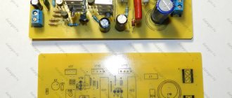
MAX98357 I2S Audio Breakout Board
After we know that we can use the I2S communication protocol to receive audio data from the microcontroller without any quality degradation, the next problem is that we have to decode the I2S signals into analog signals and also we need an amplifier to use the speaker .
- Decoder
from I2S signal to analog signal, because speakers only work with analog signals. - The amplifier
increases the power of the analog signal to increase the intensity of the sound.
The MAX98357 is a digital pulse code modulation (PCM) input amplifier that decodes the I2S signal to an analog signal using a digital-to-analog converter (DAC) and also has an integrated amplifier. The following figure shows a simplified block diagram from the MAX98357 datasheet.
Original image
From the MAX98357 block diagram, you can see that the I2S signal is first converted to an analog signal through a DAC, and the afterwords are amplified by an amplifier with a preset gain control.
What is the difference between an audio interface and a sound card?
This sounds like it's about settings for a Mac/PC joke, but it's actually a great question. Essentially, a sound card and an audio interface do the same job - converting analog signals to digital and vice versa. But sound cards are installed inside, and audio interfaces are installed outside. In addition, audio interfaces provide greater control over audio quality, offering features such as line-level analog inputs, XLR inputs, phantom power for a condenser microphone, and the ability to record multiple instruments simultaneously.
Audio Breakout Board MAX98357 Specification
You can buy the MAX98357 as a breakout board from Adafruit or SparkFun. The products are exactly the same. The following table shows the data sheet for the MAX98357.
| Adafruit MAX98357A or SparkFun MAX98357A | Meaning |
| Supply voltage range | 2.7…5.5 V |
| output power | 3.2 W into 4 ohms at 5 V 1.8 W into 8 ohms at 5 V |
| Output channel selection | left, right or left / 2 + right / 2 (default) |
| Sampling frequency | 8 kHz…96 kHz |
| Sampling resolution | 16/32 bit |
| Quiescent current | 2.4 mA |
| Class Booster | D |
| Gain | 3 dB...15 dB (default: 9 dB) |
| Memory clock (MCLK) required? | No |
The MAX98357 operating voltage ranges from 2.7V to 5.5V. Therefore, you can power a microcontroller with an Arduino (5V) or ESP (3.3V) based board. Output power is 3.2 W for a 4-ohm speaker and 1.8 W for an 8-ohm speaker.
The default board configuration is “mono,” meaning the left and right signals are combined together to drive a single speaker. If you want to switch to stereo audio, you need to cut the mono jumper on the board and solder a stereo connection for the left or right channel.
The MAX98357's sample rate ranges from 8 kHz to 96 kHz, so the music in our 44.1 kHz example is ideally suited to that sample rate. The sampling resolution is 16 or 32 bits, and the quiescent current is very low at 2.4 mA.
Since the amplifier uses pulse width modulation to control output devices, it is classified as a Class D amplifier. The amplifier's gain ranges from 3dB to 15dB with a default gain of 9dB. The following table shows how to change the gain. The key point is that the gain pin must be connected to other pins to change the gain.
| Gain | Connecting the GAIN pin |
| 15 dB | Connected to GND via 100 kOhm resistor |
| 12 dB | Connected to GND |
| 9 dB | No connection (default) |
| 6 dB | When connected to VDD/Vin |
| 3 dB | Connected to VDD/Vin via 100k ohm resistor |
Types of Audio Interfaces
Audio interfaces connect to your computer in the same way as other peripheral devices: through ports on the computer.
USB
USB audio interfaces are suitable for podcasters and solo artist/composers who typically only need to record one source at a time and hear what comes out of their DAW.
Firewire/Thunderbolt
More powerful USB, firewire, and thunderbolt audio interfaces typically have more input and output options and can handle latency better due to higher signal throughput.
Which audio interface is suitable?
Whether you choose a USB, Firewire, or Thunderbolt audio interface depends on your computer's ports and how you'll use it. If you plan to record multiple channels at the same time (like a full drum kit), you'll want to choose a higher-bandwidth connector like Firewire or Thunderbolt. If you just hum along to your masterpiece, then USB will be quite enough.
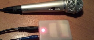
How to Record and Visualize Data Using an I2S Microphone
In the first example, we begin recording and visualizing audio data from adafruit's I2S SPH0645 microphone microcontroller. In this example we are using an ESP32 NodeMCU microcontroller.
The following figure shows the wiring between the ESP32 NodeMCU and the SPH0645 breakout board.
It is important to connect the I2S microcontroller to the 3.3V pin only. The following Arduino code visualizes analog audio data in an Arduino serial plotter.
#include "driver/i2s.h" const i2s_port_t I2S_PORT = I2S_NUM_0; void setup() { Serial.begin(115200); esp_err_t err; // The I2S config as per the example const i2s_config_t i2s_config = { .mode = i2s_mode_t(I2S_MODE_MASTER | I2S_MODE_RX), // Receive, not transfer .sample_rate = 16000, // 16KHz .bits_per_sample = I2S_BITS_PER_SAMPLE_32BIT, // could only get it to work with 32bits .channel_format = I2S_CHANNEL_FMT_ONLY_RIGHT, // use right channel .communication_format = i2s_comm_format_t(I2S_COMM_FORMAT_I2S | I2S_COMM_FORMAT_I2S_MSB), .intr_alloc_flags = ESP_INTR_FLAG_LEVEL1, // Interrupt level 1 .dma _buf_count = 4, // number of buffers .dma_buf_len = 8 // 8 samples per buffer (minimum) }; // The pin config as per the setup const i2s_pin_config_t pin_config = { .bck_io_num = 26, // Serial Clock (SCK) .ws_io_num = 25, // Word Select (WS) .data_out_num = I2S_PIN_NO_CHANGE, // not used (only for speakers) .data_in_num = 33 // Serial Data (SD) }; // Configuring the I2S driver and pins. // This function must be called before any I2S driver read/write operations. err = i2s_driver_install(I2S_PORT, &i2s_config, 0, NULL); if (err != ESP_OK) { Serial.printf("Failed installing driver: %d\n", err); while(true); } err = i2s_set_pin(I2S_PORT, &pin_config); if (err != ESP_OK) { Serial.printf("Failed setting pin: %d\n", err); while(true); } Serial.println("I2S driver installed."); } void loop() { // Read a single sample and log it for the Serial Plotter. int32_t sample = 0; int bytes_read = i2s_pop_sample(I2S_PORT, (char *)&sample, portMAX_DELAY); // no timeout if (bytes_read > 0) { Serial.println(sample); } }
In the first line we include the I2S library for the ESP32 and define the I2S pinout structure used because only GPIO25 and GPIO26 are connected to the internal 8-bit DAC, which is also shown in the ESP32 pinout.
In the setup function, we set the baud rate to 115200, which should match the baud rate in the Arduino IDE serial plotter where we display the analog audio data.
If we get any error while executing the code, we can access the error using err variable.
The next step in the Arduino code is to define the I2S communication structure. We set the following settings:
- set I2S mode to RX to receive I2S data
- use default sample rate 16 kHz
- set bit per sample to 32 rather than 16
- we only use the right microphone channel
- we use 4 buffers, each 8 long
Once we have established the I2S communication structure, we define the pins that are used on the ESP32 NodeMCU for communication. In my case I choose:
- Sequential clock (SCK) = 26
- Word Choice (WS) = 25
- Serial Data (SD) = 33
- The next section configures the I2S driver and pins. Since this part of the code dives deep into the internal functions of the ESP32, we are skipping the explanation of this section.
In the loop function we read the analog output from the DAC and store the data in the bytes_read variable. If we receive data, we output an analog audio signal to the serial output to visualize the audio frequency in the serial plotter.
The following picture shows the analog output of the serial monitor when I am playing music from my computer and the microphone is listening.
Do I need an audio interface?
The answer to this question depends on how you create music and, to some extent, on the type of music you create. If, for example, you work exclusively in EDM, and everything you create is based solely on samples and software instruments (and you're only comfortable working with headphone mixes), then the stereo output of the built-in sound card that came with your computer will be quite sufficient .
It's a completely different matter if your musical adventures involve recording sound. Let's say you're a singer-songwriter planning to record vocals with a microphone, or want to dust off your trusty old Fender Strat to bang out a riff, you'll need a way to get the audio into your computer. If you want to record both instruments at the same time, you will need two inputs to record separate tracks.
Likewise, if you want to save your ears from fatigue or annoy your neighbors by connecting external speakers, you'll need a way to bring sound out of the digital realm and into wall-shaking territory. Buy an audio interface.
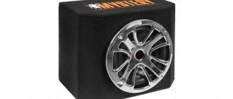
How to Play Music from ESP32 Internal Memory
In the second example, we want to play music through a speaker. The audio data is stored as an array in the ESP32's internal RAM. We use MAX98357 I2S audio jack board to convert digital signal to analog. Therefore, we use the I2S protocol to output digital audio data without losing quality.
The following figure shows the wiring between the ESP32 NodeMCU, the MAX98357 I2S breakout board, and the speaker.
For the Arduino code we use the ESP8266Audio library from Earle F. Philhower. To include this library in your Arduino, follow 4 steps:
- Download the github folder as a zip file
- unzip the downloaded folder
- rename the extracted folder to ESP8266Audio
- copy the folder to your Arduino IDE library path (in my case: C:\Users\chris\Documents\Arduino\libraries)
We use the following Arduino code from the sample library to play music from internal memory.
#include "AudioGeneratorAAC.h" #include "AudioOutputI2S.h" #include "AudioFileSourcePROGMEM.h" #include "sampleaac.h" AudioFileSourcePROGMEM *in; AudioGeneratorAAC *aac; AudioOutputI2S *out; void setup() { Serial.begin(115200); in = new AudioFileSourcePROGMEM(sampleaac, sizeof(sampleaac)); aac = new AudioGeneratorAAC(); out = new AudioOutputI2S(); out -> SetGain(0.125); out -> SetPinout(26, 25, 22); aac->begin(in, out); } void loop() { if (aac->isRunning()) { aac->loop(); } else { aac -> stop(); Serial.printf("Sound Generator\n"); delay(1000); } }
In the first lines we add the following header files from the ESP8266Audio library:
- AudioGeneratorAAC: Audio output generator using Helix AAC decoder.
- AudioOutputI2S: base class for I2S interface port
- AudioFileSourcePROGMEM: Save the "file" as a PROGMEM array and use it as audio source data.
- sampleaac: header file in which the audio file is stored as an array
Digital audio data is stored in the header file sampleaac. To load Arduino code with a header file into EPS32, it is important that the Arduino (.ino file) and the header (.h file) are in the same folder.
Once we have included the ESP8266Audio library header files, we give the first three included files variables containing references to the classes of those files.
In the setup function we set the baud rate to 115200 and initialize the header files. For AudioFileSourcePROGMEM, we define that the sample audio file is in the file sampleaac with the size of the array containing it.
The AudioOutputI2S object has different functions. We use the SetGain function to reduce the speaker volume and define the pinout using the SetPinout function. In my case I choose the following default pinout:
- Sequential clock (SCK) = 26
- Word Choice (WS) = 25
- Serial data (SD) = 22
But feel free to choose other digital pins of the EPS32 microcontroller.
The final step of the setup function is to connect the audio input data from the program's internal memory to the I2S audio output using AudioGeneratorAAC.
In the loop function, the sound generator continues to run until the entire audio array has passed through the generator. When the generator completes its operation, it will report this to the serial output.
How to Play WAVE File on ESP32 from External SD Card
In our latest project, we want to play the WAVE file that I mentioned at the beginning of this tutorial through an ESP32 NodeMCU and a speaker. Since the ESP32 must read the WAVE file and forward the digital audio signal to the MAX98357A, we must use an SD card with the WAVE file on it. You can also use an MP3 file instead of a WAVE file.
The following figure shows the connection of ESP32 NodeMCU to (Micro)SD card module, MAX98357A and speaker. In the picture you can see that you need to change the DIN pin MAX98357A compared to the second project.
Before we dive into the Arduino code, we must prepare the (Micro) SD card. The file system must be FAT16 or FAT32. Depending on the SD card module, there is a 32GB limit for the SD card. I use a 32GB micro SD card formatted as FAT32 and copy the WAVE file without the folder to the SD card.
For this project we are using the ESP32-audioI2S Arduino library from schreibfaul1. You can download the library as a zip file from its GitHub page. Since the library is named audio and there is already a library with the same name in Arduino, we enable the library through the Arduino IDE:
- Open the Arduino IDE.
- Go to (see next picture): Sketch → Include Library → Add .ZIP Library…
- Select downloaded library
The Arduino script is based on schreibfaul1's example script, but I have shortened the script leaving only the parts needed to play the WAVE file and removed all the parts for WiFi streaming.
#include "Audio.h" #include "SD.h" #include "FS.h" // Digital I/O used #define SD_CS 5 #define SPI_MOSI 23 #define SPI_MISO 19 #define SPI_SCK 18 #define I2S_DOUT 25 #define I2S_BCLK 27 #define I2S_LRC 26 Audio audio; void setup() { pinMode(SD_CS, OUTPUT); digitalWrite(SD_CS, HIGH); SPI.begin(SPI_SCK, SPI_MISO, SPI_MOSI); Serial.begin(115200); SD.begin(SD_CS); audio.setPinout(I2S_BCLK, I2S_LRC, I2S_DOUT); audio.setVolume(10); // 0…21 audio.connecttoFS(SD, “Ensoniq-ZR-76-01-Dope-77.wav”); } void loop() { audio.loop(); } // optional void audio_info(const char *info) { Serial.print("info "); Serial.println(info); } void audio_id3data(const char *info) { //id3 metadata Serial.print("id3data "); Serial.println(info); } void audio_eof_mp3(const char *info) { //end of file Serial.print("eof_mp3 "); Serial.println(info); } void audio_showstation(const char *info) { Serial.print("station "); Serial.println(info); } void audio_showstreaminfo(const char *info) { Serial.print("streaminfo "); Serial.println(info); } void audio_showstreamtitle(const char *info) { Serial.print("streamtitle "); Serial.println(info); } void audio_bitrate(const char *info) { Serial.print("bitrate "); Serial.println(info); } void audio_commercial(const char *info) { //duration in sec Serial.print("commercial "); Serial.println(info); } void audio_icyurl(const char *info) { //homepage Serial.print("icyurl "); Serial.println(info); } void audio_lasthost(const char *info) { //stream URL played Serial.print("lasthost "); Serial.println(info); } void audio_eof_speech(const char *info) { Serial.print("eof_speech "); Serial.println(info); }
In the first part of the Arduino script for ESP32, we include all the libraries and define the pins that are used to connect the ESP32 NodeMCU to the MAX98357A and SD card module.
Once the Audio object named "audio" is initialized, the configuration function is called. The configuration function defines the pins and SPI connection for communication with the SD card. The baud rate is set to 115200 and the SD card object is also initialized.
For the audio object we set the pinout, and reduce the audio volume to 10. You can adjust the audio volume from 0 to 21. The last part of the setup function is connecting the inputs and outputs in this example. So we associate the audio object with the SD card object and define the path to the WAVE file. If you are placing an audio file in a folder, you need to copy the entire path to the audio file followed by a forward slash ("/").
In the loop function, we only need to iterate over the pre-configured audio object to play music.
The last part is interesting if you want to print some details of the audio file on a serial monitor. The following figure shows the serial output in my example. The first section contains ESP32 boot information that is displayed on the serial monitor when the baud rate is set to 115200.
In the first part of this article, I calculated the frequency for the serial port clock to be 44.1 kHz * 16 * 2 = 1.411 MHz. Now I want to prove that the frequency of the I2S connection (SCK serial clock) between ESP32 and MAX98357A is 1.411 MHz. So I connected the CLK line to my USB oscilloscope and added a frequency measurement.
The following figure shows that my calculations are correct and the frequency is 1.411 MHz.