Help a beginner: amplifier Radiotekhnika, Amphiton or Odyssey and do I need a DAC in my system?
I had experience of listening, including on my own acoustics (amphiton 25 ac), of the above-mentioned amplifiers, except for the Odyssey - I listened to it at a party on the C90.
u101 - I didn’t like the fact that it sounds a bit muddy, it’s probably in the preamplifier, in mind, according to the circuit, everything is very beautiful, if only it weren’t for the power supply limitation of 26 volts for the final part. Because of this, more than 20 watts per 4 ohm load cannot be removed from it.
amphiton - well, in general, it’s quite a balanced and pleasant sound, it doesn’t tire you. Of course, regarding V. Shushurin’s publications in the magazine, Radivo has some simplifications, but it’s quite possible to listen, due to the shortcomings again - the power of 25 watts is still not enough to heartily blast some AC/DC. An important part of prevention - in addition to setting the quiescent currents and 0 at the output - is to replace the feed-through electrolytes with at least normal imported ones, at the output the pre (I think, I don’t remember) will greatly spoil the sound, even if the device shows that their ESR is only slightly higher than normal .
The Odyssey will certainly be better in all respects - it has a good phono stage, enough watts, and there are no complaints about the sound.
But I prefer the earlier Soviet amplifiers on KT808, like Shushurin 78, Uku 020, Brig 1 series.
I don’t know how to explain all this, but they have such a parameter as musicality in a much better form, in comparison with the amplifiers on the KT818/819. Live instruments sound completely different, there is no feeling of muddiness in the mid-high frequency region from the word at all, if you turn it up louder, the sound becomes even more open and involving. There is a suspicion that the issue is the higher cutoff frequency of 808 transistors, which directly affects the speed of the amplifier.
Uku 020 of the above is the most affordable option, and the difference in sound with the brig is hardly noticeable - there are also disadvantages: domestically produced slide controls are of so-so quality, they can rustle, sometimes this can be treated by lubrication, sometimes not and only replacement, with great accuracy they also do not possess. This amplifier will also not fit into a rack, since its width is not standard - 48 cm. Well, before you use it, it requires preventive maintenance and maintenance - setting up protection, setting quiescent currents, setting the output level from the limit and overload indication. Otherwise the sound may be a little different from what it should be. Well, that is, we still have to invest in it, as well as in all vintage equipment of domestic production. One of the serious shortcomings is that there is no protection unit, so when turned on there is a bang due to transient processes. I was lucky, I got this uku for an inexpensive price, from the day I made it - I haven’t turned on the Pioneer A-30 anymore. The difference in their sound is too significant.
How to read and understand amplifier specifications?
Operating frequency range or reproduced frequency range
The German standard DIN 45500, adopted back in 1974 and defining a group of criteria for compliance of audio equipment with the Hi-Fi class (High Fidelity), declares that the operating frequency range of the amplifier must extend from at least 20 Hz to 20 kHz. At the same time, as in the case of acoustic systems, one must remember that the boundaries of this range themselves do not say anything - they become informative only when supplemented with measurement conditions.
The operating frequency range is defined as the boundary frequencies within which the unevenness of the amplitude-frequency response remains in a certain “corridor”. For an absolutely horizontal frequency response, the width of this corridor will be 0 dB, since there is no unevenness of the characteristic in this case. But amplifiers with such an frequency response are not encountered in real life, therefore, when measuring real devices, certain unevenness tolerances are set and violations of these tolerances are recorded. It is clear that the wider the corridor (rougher the tolerances), the longer the operating frequency range will be. And the main thing here is not to disavow the indicator itself in the pursuit of beautiful numbers. In other words, the operating frequency range of an amplifier, determined, for example, by a level of -10 dB, will most likely look very nice, but will turn out to be completely useless, because you most likely simply will not hear the sound of a certain frequency with a level of -10 dB relative to the general flow of audio information .
Most often, the frequency range is determined by a level of -3 dB, but sometimes more stringent conditions are used. In this case, for example, an amplifier can demonstrate an operating range from 20 Hz to 20 kHz with unevenness of +/- 0.1 dB, and when the corridor is expanded to +/- 3 dB, its frequency range will be from 10 Hz to 100 kHz. For a modern transistor amplifier, these are quite achievable indicators.
In this regard, we note two points. Firstly, the value of any parameter for the system as a whole is determined by the most “bottleneck” - the component with the worst value of this parameter. For an audio system, according to most parameters, such a link will be speakers, for which, for example, the operating range from 20 Hz to 20 kHz with unevenness of +/- 0.1 dB is practically unattainable. Secondly, if you include your hearing aid into consideration (as part of the system), then perhaps it will be the bottleneck - with age, hearing acuity decreases, especially in the high-frequency region. As a result, speaking about the operating frequency range of the amplifier, you only need to ensure that this range exceeds the capabilities of the acoustic systems with which it works, and in the operating frequency range of the acoustics demonstrates minimal unevenness in the frequency response.
Amphiton A1-01-stereo
0
The device, very similar to the Japanese amplifiers of those years, was produced since 1982 by the Lvov LPO named after. Lenin. It had separate loudness controls for the channels, separate tone controls for bass, midrange and treble, as well as electronic overload protection. There were also built-in limiting filters for low-pass and high-pass. The rated output power was 2 x 20 Watts, the frequency range was from 20 to 20,000 Hz. The amplifier weighed 9.5 kilograms and cost 385 rubles.
9.
Corvette 50U-068S
0
The model was produced by Kirovsky, who produced it since 1987. It used the technical solutions of the Brig-001-stereo amplifier, and for the first time used a LAN-class power amplifier with two-level power supply. The built-in phono preamplifier could work not only with MM, but also with MC heads, and the volume control had variable loudness compensation. The rear panel also had a power outlet for connecting other system components. The amplifier output power was 60 watts per channel, and the stated frequency range was from 10 to 70,000 Hz. The device weighed 10.8 kilograms and cost 650 rubles.
7.
Corvette UP-078S/ Corvette 200UM-088S
0
11.
0
A combination of a preamplifier and a power amplifier. The Corvette UP-078S preamplifier has been produced by Kirovsky since the beginning of 1991. It was designed for switching, amplification and frequency correction of signals from a vinyl player with an MM or MC pickup head, a CD player, a tuner and two tape recorders. The Corvette 200UM-088S power amplifier has been produced at the same plant since 1990. It had a solid power for Soviet amplification technology - up to 180 watts at 8 ohms, as well as extremely low intrinsic noise and distortion. The device was built according to a dual mono circuit and had light indicators for power on, output overload, and protection device activation. The dimensions of the model were 430x375x130 mm, it weighed 13 kilograms.
12.
Radio engineering-020-stereo
0
This complete amplifier has been produced by the Riga Radio Plant named after Popov since 1977. It had a built-in phono stage, as well as a full set of line inputs, and it was also possible to connect headphones. On the left side of the front panel there were arrow indicators for the output signal level, and the kit also included a wireless remote control - a rarity in those years. The amplifier power was 50 watts per channel at 8 ohms, the weight of the device was 12 kilograms. The model cost 350 rubles.
5.
Ultra linear power amplifier (100 W/8 ohms)
In 1975, reports appeared on the pages of amateur radio magazines in many countries about the creation of powerful ultra-linear low-frequency amplifiers, in which the final stages were made using field-effect transistors. We were talking about qualitatively new high- and ultra-high-frequency amplification devices - the so-called MOSFETs with a vertical gate structure. It turned out that high-power field-effect transistors, designed for use in high- and ultra-high-frequency transmitters, can successfully work in low-frequency power amplifiers. Thus, already the first samples of amplifiers with field-effect transistors in the final stages had an output power of up to 100 W per channel with a harmonic distortion coefficient of no more than 0.01%. At mid-frequencies, signal distortion was so small that it was difficult to measure with existing measuring instruments. We are talking about the harmonic distortion coefficient at the level of 0.002 - 0.003%. Field-effect transistors have much better performance in amplifying a signal without distortion, but devices suitable for operation in final stages appeared only in the early 70s.
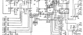
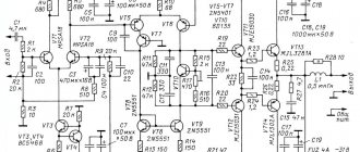
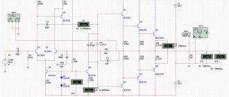
The figure shows a schematic diagram of the amplifier:
Specifications:
Frequency range: 10 – 600000 Hz
Output load: 8 ohms
Power: 100W
Harmonic Distortion: 0.002%
As can be seen from the figure, an amplifier using a differential circuit on transistors T1, T2 and T3, T4, a pre-amplifier stage on transistor T5 and a final stage with a transformerless output according to a circuit with additional symmetry on field-effect transistors (T6, T7 and T8, T9) with different type of channel conductivity. The initial bias on the gates of transistors T6, T7 and T8, T9, connected in pairs in parallel, is regulated by a variable resistor R13. To protect the gates of field-effect transistors from large voltage surges observed when the amplifier is turned on and off when operating with an overload, additional diodes D2 - D5 are used. To reduce the influence of the scatter in the input characteristics of field-effect transistors on the operation of the amplifier as a whole, 220 Ohm resistors R14 – R17 are included in the gate circuit of transistors T6 – T9.
The use of transistors connected in pairs in the final stage makes it possible to obtain an output power of 100 W with a load resistance of 8 Ohms. If you use only one field-effect transistor and a load with a resistance of 16 Ohms, the output power will be 50 W. In one of the designs, the final stage of a 60 W amplifier uses six field-effect transistors connected in parallel, three at a time. In this regard, field-effect transistors have great advantages over bipolar ones, the parallel connection of which is difficult.
It is necessary to note two characteristic features of the amplifier. The first is that four power supplies are used: two unstabilized to power the final stage, and two stabilized to power the preliminary stages. The second feature is that three correction circuits R18С8, R20С9 and R19, L1 are included at the amplifier output. The purpose of RC circuits is to prevent self-excitation of the amplifier at high and ultra-high frequencies. A circuit consisting of inductor L1, shunted by resistor R19, reduces harmonic distortion of the signal at frequencies above 3 - 4 kHz. It turns out that in the absence of this circuit, the amplifier's harmonic distortion coefficient at high frequencies is about 0.01%, and with the circuit it decreases to 0.002%. Unfortunately, foreign literature does not indicate the data for inductor L1, so when repeating the design of the amplifier, it is necessary to select the winding data experimentally.
Only high-voltage, high-frequency silicon transistors can be used in the amplifier. If you do not strive to achieve a very high output power and limit yourself to a limit of 30 - 40 W, then you can reduce the voltage of each of the four power supplies to 40 V and use domestic transistors: type KT626 with any letter indices (T1, T2, T5), type KT602 also with any subsequent letter indices (T3, T4) and field-effect transistors such as KP904A (T6, T7), KP901A (T8, T9). Diodes D1, D2, D5 type D220; D3 and D4 – type KS156A. Input socket Gn1 type SG-3 or SG-5.
Setting up an amplifier with four power supplies comes down to setting the variable resistor R13 to such a bias voltage on the gates of field-effect transistors that the initial drain current of each field-effect transistor is about 50 mA. With such an initial current, “step” signal distortion is almost completely eliminated.
When starting to work with field-effect transistors, it is necessary to take into account their tendency to breakdown of the gate under the influence of a discharge of static electricity, therefore it is necessary to comply with the conditions specified in the instructions supplied with the transistor. It should also be taken into account that field-effect transistors in general and powerful ones in particular are devices of a new type, so their acquisition may be associated with a number of difficulties.
It remains to be recalled that field-effect transistors operating in final stages, like their predecessors bipolar transistors, require the use of efficient heat sinks. True, field-effect transistors have one important advantage: they are not afraid of a short circuit at the output. If this happens, the channel temperature increases and its current decreases.
Arcturus-001-stereo
0
An amplifier of original design, reminiscent of solutions from Western European manufacturers, has been produced by the Berdsk Radio Plant since 1976. The front panel contains all the main controls, as well as dial indicators of the signal level. On the rear panel you can see massive cooling radiators and transistors in round cases. The output power of the device was 25 watts at 8 ohms, there was loudness compensation and a tone block for high frequencies and low frequencies. The frequency band ranged from 20 to 20,000 Hz, the nonlinear distortion coefficient was 0.7%. The weight of the device is 14 kilograms.
4.
Forum U-001-stereo
0
This stereo amplifier has been produced by the Leningrad Kalinin Plant since 1987. It had a built-in phono stage, low-pass and high-pass filters and a tone block, as well as loudness. The output signal power indicators were electronic. There was also a headphone output on the front panel. The output stages were protected against short circuits, overheating and the presence of constant voltage. The rated power was 100 Watts at 8 Ohms, the THD did not exceed 0.05%, the intermodulation distortion coefficient did not exceed 0.01%. The device weighed 17 kilograms.
6.
What you won't find in the garage
Many people probably know that people usually store things in garages that they would hate to throw away. This habit was especially preserved among people who lived during the Soviet era. This is not the first time I have seen such a picture, but this collection of antiques turned out to be really quite large. Since I had a camera handy, I took a few pictures of these wonderful things.
Many people remember the times when they listened to music on reels or records. An amplifier was almost always used to listen to music. Personally, at home I had a 100-watt Odyssey amplifier, Orbit speakers and other equipment, my father is a music lover. I still use the speakers today. These three-way speakers are simply amazing sounding. But I had to buy a newer amplifier.
Well, let's see what I found in my friend's garage. It was not he who collected the collection, but his father.
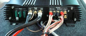
Amplifier Spectrum 100, 400 Watt (they say that in the USSR it cost 900 rubles). Of course, you don’t want to throw this away.
Amphiton 25-u 101s (power 50W)
“Vega-312” is a third-class household stereo radio, produced in 1974 by the Berd Radio Plant.
A stereophonic single-speed cassette tape recorder of III complexity group provides recording of stereo and monophonic music and speech programs with subsequent playback of the tape through its own loudspeakers, external speaker systems or stereo telephones. They were released from 1987 to 1991 somewhere.
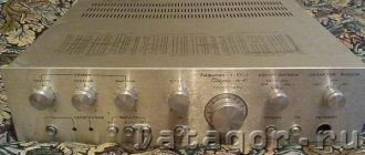
Old Soviet amplifiers and radios.
Well, here are other items that remind us of the old days.
Soviet device for measuring air humidity and atmospheric pressure.
Metal cup holders.
And this is a little thing that reminded me of my childhood. These miniature cars were quite popular in the second half of the 90s. The best part was that they were metal. Although in fact, the alloy from which they were made was not very strong. At that time, we had no idea that in 10-15 years, almost everyone would be able to record their own videos and easily edit them on computers using special programs that can be downloaded from the video editor website.
A popular toy of my childhood. Chinese machine.
And most importantly, I almost forgot.
But is there still something good in this - or not?
Rate the post!
( 6 votes, rating: 5.00 out of 5)
Loading…
Articles on the topic
- 02/12/2012 Methods of website promotion When creating a new website for one purpose or another, its analysis is not always done and its further thought through […] Posted in Website promotion, Advertising, Internet business
- 07/18/2013 Removing the AGS filter from Yandex Finally, my blog was completely freed from all sanctions from the Yandex search engine. Let me remind you, […] Posted in News, Website promotion, Web analytics
- 11/27/2014 Making money online With the rapid development of the Internet, you can increasingly find work on the World Wide Web. Now working in […] Posted in Earning money online
Zemanta