Having bought a good laptop or a cool phone, we rejoice at the purchase, admiring the many functions and speed of the device. But as soon as we connect the gadget to the speakers to listen to music or watch a movie, we understand that the sound produced by the device, as they say, “let us down.” Instead of full and clear sound, we hear an unintelligible whisper with background noise.
But don’t get upset and scold the manufacturers; you can solve the sound problem yourself. If you know a little about microcircuits and know how to solder well, then it will not be difficult for you to make your own audio amplifier. In our article we will tell you how to make a sound amplifier for each type of device.
DIY SOUND AMPLIFIERS
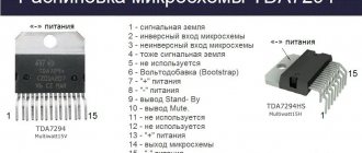
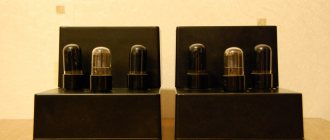
In this article we will talk about amplifiers. They are also ULF (low frequency amplifiers), they are also UMZCH (audio frequency power amplifiers). These devices can be made on both transistors and microcircuits. Although some radio amateurs, paying tribute to the vintage fashion, make them the old fashioned way - using lamps. Here we recommend you look at an excellent collection of schemes. I would like to draw special attention of beginners to car amplifier microcircuits with 12-volt power supply. Using them you can get a fairly high-quality sound output, and for assembly, knowledge of a school physics course is practically enough. Sometimes from the body kit, or in other words, those parts on the diagram without which the microcircuit will not work, there are literally 5 pieces on the diagram. One of these, an amplifier based on the TDA1557Q , is shown in the figure:
Amplifier on TDA1557Q chip
Such an amplifier was assembled by me at one time; I have been using it for several years together with Soviet 8 Ohm 8 W acoustics, together with a computer. The sound quality is much higher than that of Chinese plastic speakers. True, in order to feel a significant difference, I had to buy a creative sound card; the difference with the built-in sound was insignificant.
The amplifier can be assembled by hanging mounting
The amplifier can also be assembled by hanging mounting, directly on the terminals of the parts, but I would not recommend assembling using this method. It’s better to spend a little more time, find a wired printed circuit board (or wire it yourself), transfer the design to the PCB, etch it and end up with an amplifier that will work for many years. All these technologies have been described many times on the Internet, so I will not dwell on them in more detail.
Amplifier attached to radiator
I’ll say right away that amplifier chips get very hot during operation and need to be secured by applying thermal paste to the radiator. For those who just want to assemble one amplifier and do not have the time or desire to study programs for PCB layout, LUT technologies and etching, I can suggest using special breadboards with solder holes. One of them is shown in the photo below:
Photo assembly on a breadboard
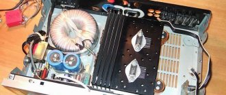
As can be seen in the photo, connections are made not by tracks on a printed circuit board, as is the case with printed wiring, but by flexible wires soldered to the contacts on the board. The only problem when assembling such amplifiers is the power supply, which produces a voltage of 12-16 volts, with a current consumption by the amplifier of up to 5 amperes. Of course, such a transformer (5 amperes) will have rather large dimensions, so some people use switching power supplies.
Transformer for amplifier - photo
I think many people at home have computer power supplies that are now obsolete and are no longer used as part of system units, but such power supplies are capable of delivering +12 volts through circuits, currents much greater than 4 amperes. Of course, such power supply among sound connoisseurs is considered worse than a standard transformer one, but I connected a switching power supply to power my amplifier, then changed it to a transformer one - the difference in sound can be said to be imperceptible.
Diode for amplifier rectifier
After leaving the transformer, of course, you need to install a diode bridge to rectify the current, which must be designed to work with the large currents consumed by the amplifier.
Electrolytic capacitor 2200 µF
After the diode bridge there is a filter on an electrolytic capacitor, which should be designed for a noticeably higher voltage than in our circuit. For example, if we have a 16 volt power supply in the circuit, the capacitor should be 25 volts. Moreover, this capacitor should be as large as possible; I have 2 capacitors of 2200 μF connected in parallel, and this is not the limit. In parallel with the power supply (bypass), you need to connect a ceramic capacitor with a capacity of 100 nf. At the input of the amplifier, film decoupling capacitors with a capacity of 0.22 to 1 µF are installed.
Film capacitors
Connecting the signal to the amplifier, in order to reduce the level of induced interference, should be done with a shielded cable; for these purposes, it is convenient to use a Jack 3.5 - 2 Tulip cable, with the corresponding sockets on the amplifier.
Cable jack 3.5 – 2 tulips
The signal level (volume on the amplifier) is adjusted using a potentiometer, if the amplifier is stereo, then dual. The connection diagram for the variable resistor is shown in the figure below:
Connecting a potentiometer to an amplifier - diagram
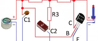
Of course, amplifiers can also be made using transistors, while power supply, connection and volume control are used in them in exactly the same way as in amplifiers on microcircuits. Consider, for example, an amplifier circuit using a single transistor:
Amplifier with 1 transistor circuit
There is also a separating capacitor here, and the minus of the signal is connected to the minus of the power supply. Below is a diagram of a push-pull power amplifier with two transistors:
Push-pull transistor power amplifier
The following circuit also uses two transistors, but is assembled from two stages. Indeed, if you look closely, it seems to consist of 2 almost identical parts. Our first cascade includes: C1, R1, R2, V1. In the second stage C2, R3, V2, and the load headphones B1.
Two-stage transistor amplifier - circuit diagram
If we want to make a stereo amplifier, we will need to assemble two identical channels. In the same way, we can, by assembling two circuits of any mono amplifier, turn it into stereo. Below is a diagram of a three-stage transistor power amplifier:
Three-stage transistor amplifier - circuit diagram
Amplifier circuits also differ in supply voltage, some require 3-5 volts to operate, others require 20 or more. Some amplifiers require bipolar power to operate. Below are 2 amplifier circuits on the TDA2822 , the first is a stereo connection:
Stereo connection TDA2822m
In the diagram, speaker connections are indicated in the form of resistors RL. The amplifier operates normally at 4 volts. The following figure shows a bridged circuit that uses one speaker, but produces more power than the stereo version:
Bridge connection TDA2822m
The following figure shows the amplifier circuits on the TDA2030 chip, both circuits are taken from the datasheet. Power supply 18 volts, power 14 watts:
Chip tda 2030 circuit diagram
The following shows the same microcircuit in a bridge connection (or rather, there are two of them used here):
Bridge amplifier circuit for tda 2030
The acoustics connected to the amplifier can have different impedances, most often it is 4-8 ohms, sometimes there are speakers with a resistance of 16 ohms. You can find out the speaker's resistance by turning it over with its back side facing you; the rated power and resistance of the speaker are usually written there. In our case it is 8 ohms, 15 watts.
Photo of the speaker from the back
If the speaker is inside the column and there is no way to see what is written on it, then the speaker can be ringed with a tester in ohmmeter mode by selecting a measurement limit of 200 Ohms.
Multimeter in ohmmeter mode measures the speaker
Speakers have polarity. The cables that connect the speakers are usually marked in red, for the wire that is connected to the positive of the speaker.
Speaker cable
If the wires are not marked, you can check the correct connection by connecting the battery plus with plus, minus with minus of the speaker (conditionally), if the speaker cone moves out, then we guessed the polarity. More different ULF circuits, including tube ones, can be found in this section. It contains, we think, the largest selection of schemes on the Internet.
ULF Forum
- TRIODE AMPLIFIER
- PREAMP FOR RECORD PLAYER
- TUBE ULF FOR 6P14P AND 6N2P
- COMBO AMPLIFIER FOR ELECTRIC GUITAR
How to extend the service life of a structure
It is important to understand how to properly make an amplifier with your own hands so that it lasts even longer than purchased devices.
Many people create temporary devices based on the fact that they are affordable and easily replaceable. But in vain: you can make a long-lasting version of the amplifier yourself.
It is enough to follow a few rules:
- Ensure complete cooling of the part. You can't do without a radiator grille. It must match the size of the chip.
- Do not overload the amplifier, that is, do not send a signal constantly. One hour of work will be enough to enjoy the music, and during this time the microcircuit will not fly away from overheating.
- Turn off the device from the network if it is not receiving a signal. Microcircuits of this type consume a large amount of quiescent current, even if they are not actually turned on. Because of this, the housing heats up and the service life is reduced.
Making a modern music device out of an old music center
Car acoustics. How to make it?
We take out the old stereo system from the storage room and take the speakers from it. We find an amplifier in the car (if it is missing, turn off the rear speakers), thoroughly strip the wires on the old speakers, it is important not to confuse the polarities, and connect. The sound from the old speakers from the center is much louder and better quality than ordinary car mugs, some of them will replace the subwoofer, the main thing is not to burn it or turn the music volume up to maximum. You'll have to find the best option for setting the volume so that it doesn't gurgle.. Universal Bluetooth speaker system
How to collect it?
Universal Bluetooth speaker system. How to collect it?
To make it, we take an old stereo system and buy a Bluetooth adapter with an aux or a standard 3.5 mm jack. It all depends on the inputs on your speaker system
The price of adapters varies between two hundred and five hundred rubles. It is important to choose the right adapters so that you do not have to solder them in the future. We connect Bluetooth to our music center, set up a computer, laptop, smartphone... This assembly is perfect for an apartment
You can take the device with you to your country house by connecting your smartphone. In your car, you can connect a Bluetooth adapter to the radio and listen to music directly from the Internet via a smartphone (mobile phone)
This assembly is perfect for an apartment. You can take the device with you to your country house by connecting your smartphone. In the car, you can connect a Bluetooth adapter to the radio and listen to music directly from the Internet via a smartphone (mobile phone).
What you need to know about creating a simple KM
In addition to the power supply, there is another very important central element of a DIY home or car audio amplifier - the operational amplifier.
There are simpler models that receive unipolar power from a similar source. But most of the really good amps are bipolar.In addition, when creating an audio amplifier, it is important to understand that the standard model has two inputs and one output. We will further consider the manufacture of such a model of a stereo audio amplifier, which has two outputs.
This design change is necessary to distribute the received signal to the right and left output speakers.
Check it out here too!
Homemade lanterns with your own hands: step-by-step instructions on how to make a beautiful and effective lantern (110 photos)Grout - use, reviews, leading manufacturers
Replacing a pressure tap - a step-by-step description of how to change a pressure tap with your own hands (80 photos + video)
The microcircuit of such a sound amplifier must have at least six terminals. One pair is needed to connect to the power supply amplifier.
The second pair is the input pair for receiving a signal to the chip. And the third pair are outputs for receiving sound through speakers.
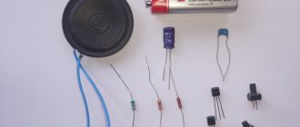
But for the most part, everything looks different and there are many more pins in the microcircuit to create windings. Let's look at what you can use to assemble a simple sound amplifier.
Marking, folding and gluing the phone stand
You need to mark all the fold lines with the tip of the scissors, and then fold the part in accordance with the photographs. Glue the back flaps down and then push up through the hole in the top of the platform until the flaps of the pieces line up. Then glue all five flaps on three sides. The valve on the bottom does not stick. It just rests against the stand when everything else is glued down.
Did you see a piece of foam or polystyrene in the door? Be careful, there are robbers at work
Ryan Goslin: 5 Stars Who Started Their Careers on The Mickey Mouse Club
Guinea pig thinks she's a Sphynx cat too
Additional Tips
Experienced radio amateurs can achieve even cleaner sound from the amplifier if they create the circuit themselves. It is quite difficult to do this without auxiliary tools.
To avoid confusion, it is recommended to use the Sprint Layout program. It has the following functions:
- designing circuits of low and medium complexity;
- wiring design;
- viewing models in three dimensions;
- ability to create a parts library.
You can download and install a Russified program with additional functionality for free. To do this, you should look for version 6 of the software (not the official one, but the translated one). It is compatible with all English versions up to the fifth.
The program will help you create visual plans that are much more useful in practice than photos of homemade sound amplifiers and their circuits.