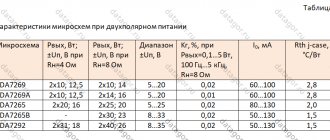
The LM383 and TDA2003 ICs are almost identical internally and externally and are generally classified by manufacturers as 8W audio amplifiers. The website radiochipi.ru presents the electrical characteristics of the LM383 and TDA2003 microcircuits. The LM383 has wider supply voltage limits (5-20 V) and a wider frequency range (30 kHz) than the TDA2003 (8-18 V and 15 kHz bandwidth).
The figure shows the functional diagram, which is the same for these two devices, and the figure shows the appearance and pinout of the IC, which is available in a plastic case like
LM383 (TDA2003) chip packages
T0220 with five terminals. Both ICs are specifically designed for car audio applications, where at a normal operating voltage of 14.4 volts they have an output power of 5.5 watts into 4 ohms or 8.6 watts into 2 ohms. IC LM383 can supply current up to 3.5 A to the load, both ICs have load current limiting function and thermal protection of the output stage.
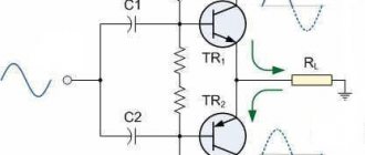
The LM383 integrated circuit is easy to use. The figure shows a practical circuit (with a circuit that increases high-frequency stability) designed for a simple 5.5-watt car audio amplifier. In this circuit, the gain is determined by the ratio of the negative feedback resistors 220 Ohm/2.2 Ohm and is 100;
The IC operates in non-inverting mode, the input signal will be applied to pin 1 through a 10 µF electrolytic capacitor. The figure shows the circuit of an amplifier for a car, in which a pair of LM383 ICs or a TDA2003 amplifier The trimmed resistor RV1 is required in this circuit to adjust the balance of the quiescent output voltages of both ICs and thereby ensures the minimum quiescent current of the circuit.
Automotive version of a 5.5-watt amplifier based on IC LM383 (TDA2003)
16-watt bridge amplifier based on IC LM383 (TDA2003) for a car.
TDA2003 is a monophonic low-frequency power amplifier (domestic analogue of K174UN14). The microcircuit develops a power of 10 W with a load resistance of 2 Ohms. The amplifier has a wide range of reproduced frequencies from 30Hz to 30KHz. The low-power amplifier is not equipped with polarity reversal protection; it is imperative to observe polarity when connecting to a power source.
TDA2003 is installed on a heat sink (radiator) with an area of at least 100 sq. The quiescent current of the microcircuit is 44mA. Supply voltage from 8V to 18V. It is not recommended to supply a signal with an amplitude of more than 1 Volt to the input of the microcircuit.
The audio power amplifier works excellently with any preamplifiers that meet all the technical parameters of the microcircuit . The amplifier is widely used in foreign car radios, as well as in portable household appliances, TVs, VCRs, etc.
DataSheet
| Functional composition: I - overload protection device; II - pre-amplifier; III - control cascade; IV - powerful output stage; V - thermal protection | Housing type 1501Yu.5-1 |
| Typical circuit diagram for connecting the K174UN14 IC as a power amplifier | Typical circuit diagram for switching on the K174UN14 microcircuit. It is allowed to change the resistance of resistors R1 and R2 (R2 = 22 Ohms) in order to change the gain of the microcircuit. Circuit R4C7 is connected in case of self-excitation of the amplifier |
| Electrical circuit diagram |
Description
The microcircuit is a low-frequency power amplifier with an output power of 4.5 W. Intended for use in the final stages of the sound reproducing equipment path and in television receivers. Compared to K174UN7, it has more advanced built-in thermal protection and protection against output short circuits, current overloads and polarity reversals, as well as a lower Kg value. Contains 86 integral elements. Housing type 1501.5-1. Weight no more than 2.5 g. The microcircuit includes: an overload protection device, a pre-amplifier, a control stage, a powerful output stage, and thermal protection.
Pin assignment: 1 - non-inverting input; 2 - inverting input; 3—general (—Up); 4 - exit; 5 — supply voltage (+Up).
General recommendations for use
A short-term increase in the supply voltage to 40 V and the input voltage to 1.5 V is allowed for a period of no more than 50 ms with a frequency of at least 0.5 s. In addition, an increase in the input voltage is allowed provided that the load resistance increases (more than 3.2 Ohms); in this case, the output power should be no more than 5.5 W. Operation of the microcircuit is allowed at Up ≥ 8 V and Rн ≥ 2 Ohm. It is necessary to use a radiator with a thermal resistance of no more than 6 °C/W at Rн = 3.2...4.8 Ohm. When attaching the microcircuit to the heat sink, it is recommended to use KPT-8 paste (GOST 19783-74). It is allowed to use the microcircuit in a switching circuit that differs from the standard one, provided that the maximum permissible mode is not exceeded. The housing temperature must not exceed 100 °C. The operation of the microcircuit Rн = 8 and 16 Ohms is allowed (in this case, the output power is reduced).
| Electrical parameters | |||
| Options | Conditions | K174UN14 | Unit change |
| Analogue | — | UL1413G, TDA2003 | — |
| Rated supply voltage | — | 15±10% | IN |
| Output voltage | at Up = 15 V | 3,6…4,6 | IN |
| Consumption current | at Up = 16.5 V | 10…80 | mA |
| Harmonic distortion | at a frequency of 1 kHz at Pout = 0.05…2 W | ≤0,5 | % |
| at a frequency of 1 kHz at Pout = 5.5 W | ≤10 | ||
| Gain attenuation factor | at the lower limit frequency at fн = 40 Hz | ≥-3 | dB |
| at the upper limit frequency at fn = 15 kHz | ≥-3 | ||
| Maximum permissible operating conditions | |||
| Options | Conditions | K174UN14 | Unit. |
| Supply voltage | — | 13,5…16,5 | IN |
| Input voltage | — | ≤42 | mV |
| Load resistance | — | ≥3,2 | Ohm |
| Thermal resistance | crystal-case | 3 | °C/W |
| Ambient temperature | — | -10…+70 | °C |
| Dependence of current consumption on supply voltage at Uin = 0, T = +25 °C | Dependence of output power on supply voltage at f = 1 kHz, Kr ≤ 10%, T = -10…+60 °C |
| Dependence of power dissipation and efficiency on output power at Up = 15 V, Ku,U = 40 dB, f = 1 kHz, Rн = 2 Ohm | Dependence of power dissipation and efficiency on output power at Up = 15 V, Ku,U = 40 dB, f = 1 kHz, Rн = 4 Ohm |
| Dependence of harmonic distortion on output power at Up = 15 V, Ku,U = 40 dB, f = 1 kHz | Amplitude-frequency response at Up = 15 V, Pout = 1 W |
If you find an error, please select a piece of text and press Ctrl+Enter.
A little trick of the TDA2003 chip (K174UN14)
Many devices use the UMZCH TDA2003 (K174un14) microcircuit; usually these are only devices powered from a lighting or automotive network. The use of the TDA2003 (K174un14) integrated circuit in portable equipment is limited by its high quiescent current.
Moreover, most of the quiescent current is spent not on the microcircuit itself, but on heating the constant resistors in the negative feedback circuit for alternating current, since these resistors, forming a total resistance of about 20 Ohms (according to a typical circuit), are under a constant voltage of the microcircuit output equal to half power supply voltage.
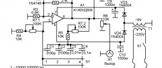
As a result, with a supply voltage of 9 volts, an excess current of 0.023 Amperes is obtained. The problem can be radically solved if the negative feedback from the output is cut by direct current, as shown in the figure. In this case, the operation of the microcircuit will not be disrupted in any way, and the quiescent current is significantly reduced.
K174UN14 – Low frequency power amplifier
| Series: | Series: | Series: | ||
| 140143148153154155 | 1591745445485541006 | 100810161022102510321103 | 110711131114119514461533 | 1816 |
The K174UN14 microcircuit (bKO.348.824TU) is a low-frequency power amplifier with a nominal output power of 4.5 W into a 4 Ohm load. The amplifier has built-in thermal protection and protection against short circuits at the output. Designed for use in automobile and stationary household sound-reproducing equipment.
Housing type 1501Yu.5-1. Weight no more than 2.5 g.
Analogue - TDA2003.
Figure 1 — Appearance of K174UN14 Figure 2 — Functional diagram of K174UN14
Figure 3 — Schematic diagram of K174UN14
Functional composition:
I—overload protection device; II—pre-amplifier; III—control cascade; IV—powerful output stage; V—thermal protection.
Pin assignment:
1—non-inverting input; 2—inverting input; 3—general (— Up); 4—output; 5—power supply (+Up).
Figure 4 - Typical connection circuit K174UN14
It is allowed to change the resistance of resistors R1 and R2 (R2 = 22 Ohms) in order to change the gain of the circuit.
Circuit R4C7 is connected if the amplifier is self-excited. Electrical parameters
| Rated supply voltage | 13.5 V |
| Current consumption at Up=16.5V, Uin=0, T=+25°C | 10…80 mA |
| Rated output power at Up=13.5 V, f=1 kHz, KG= 10%, Rn=4 Ohm, T=+25° C, not less | 4.5 W |
| Voltage amplification factor at Up=15 V, Uin=10 mV, f=1 kHz, Rн=4 Ohm, T=+25° C, not less | 40 dB |
| Output voltage at f=1 kHz, Rн=4 Ohm, T=+ 25° C: | |
| at Up=15 V, Uin=47 mV | 3.6…4.6 V |
| at Up=13.5 V, Uin=10 mV, not less | 1 V |
| Harmonic coefficient at f= 1 kHz, Rн=4 Ohm: | |
| at Pout=0.05W, Up=13.5V, Uout=0.45V, T= +25° C, no more | 0,05% |
| typical value | 0,15% |
| at Pout=2.5 W, Up=13.5V, Uout=3.16 V, T= +25° C, no more | 0,5% |
| at Pout = 5.5 W, Up=15 V, Uout=4.7 V, T=+25° C, no more | 10% |
| Input voltage at Uп=13.5 V, f=1 kHz, Uout=3.16 V, Rн=4 Ohm, T=+25°С | 20…50 mV |
Operating limits
| Supply voltage 1.2 | 13.5…16.5 V |
| Maximum input voltage 3.4 | 42 mV |
| Minimum load resistance | 3.2 ohm |
| Maximum case temperature | +100° C |
| Ambient temperature | -10…+60°С |
1 A short-term increase in the power source voltage to 40 V is allowed for a time of no more than 50 ms with a frequency of at least 0.5 s. 2 It is allowed to operate the microcircuit with a supply voltage of less than 8 V; in this case, the values of the main electrical parameters will not correspond to those established above. 3 A short-term increase in the input voltage to 1.5 V is allowed for a period of no more than 50 ms with a frequency of at least 0.5 s. 4 It is allowed to increase the input voltage provided that the load resistance is more than 3.2 Ohms and the power dissipation is not more than 5.5 W.
Figure 5 - Typical dependencies for K174UN14 References Novachenko I.V. and others. Microcircuits for household radio equipment: Handbook. - M: KUBK-a, 1996.
Chip K174UN14
Parameters of the K174UN14 microcircuit
K174UN14 microcircuit (bKO.348.824TU) is a low-frequency power amplifier with a nominal output power of 4.5 W into a 4 Ohm load.
The amplifier has built-in thermal protection and protection against short circuits at the output. Designed for use in automobile and stationary household sound-reproducing equipment. Housing type 1501Yu.5-1. Weight no more than 2.5 g. Analogue - TDA2003.
Figure 1 — Appearance of
K174UN14 Figure 2 — Functional diagram of K174UN14
Figure 3 — Schematic diagram of K174UN14
Functional composition:
I—overload protection device; II—pre-amplifier; III—control cascade; IV—powerful output stage; V—thermal protection.
Pin assignment:
1—non-inverting input; 2—inverting input; 3—general (— Up); 4—output; 5—power supply (+Up).
Figure 4 - Typical connection circuit K174UN14
It is allowed to change the resistance of resistors R1 and R2 (R2 = 22 Ohms) in order to change the gain of the circuit.
Circuit R4C7 is connected if the amplifier is self-excited. Electrical parameters
| Rated supply voltage | 13.5 V |
| Current consumption at Up=16.5V, Uin=0, T=+25°C | 10…80 mA |
| Rated output power at Up=13.5 V, f=1 kHz, KG= 10%, Rn=4 Ohm, T=+25° C, not less | 4.5 W |
| Voltage amplification factor at Up=15 V, Uin=10 mV, f=1 kHz, Rн=4 Ohm, T=+25° C, not less | 40 dB |
| Output voltage at f=1 kHz, Rн=4 Ohm, T=+ 25° C: | |
| at Up=15 V, Uin=47 mV | 3.6…4.6 V |
| at Up=13.5 V, Uin=10 mV, not less | 1 V |
| Harmonic coefficient at f= 1 kHz, Rн=4 Ohm: | |
| at Pout=0.05W, Up=13.5V, Uout=0.45V, T= +25° C, no more | 0,05% |
| typical value | 0,15% |
| at Pout=2.5 W, Up=13.5V, Uout=3.16 V, T= +25° C, no more | 0,5% |
| at Pout = 5.5 W, Up=15 V, Uout=4.7 V, T=+25° C, no more | 10% |
| Input voltage at Uп=13.5 V, f=1 kHz, Uout=3.16 V, Rн=4 Ohm, T=+25°С | 20…50 mV |
Operating limits
| Supply voltage 1.2 | 13.5…16.5 V |
| Maximum input voltage 3.4 | 42 mV |
| Minimum load resistance | 3.2 ohm |
| Maximum case temperature | +100° C |
| Ambient temperature | -10…+60°С |
1 A short-term increase in the power source voltage to 40 V is allowed for a time of no more than 50 ms with a frequency of at least 0.5 s. 2 It is allowed to operate the microcircuit with a supply voltage of less than 8 V; in this case, the values of the main electrical parameters will not correspond to those established above. 3 A short-term increase in the input voltage to 1.5 V is allowed for a period of no more than 50 ms with a frequency of at least 0.5 s. 4 It is allowed to increase the input voltage provided that the load resistance is more than 3.2 Ohms and the power dissipation is not more than 5.5 W.
Figure 5 - Typical dependencies for K174UN14 References Novachenko I.V. and others. Microcircuits for household radio equipment: Handbook. - M: KUBK-a, 1996.