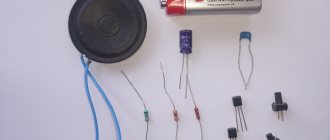
Sound amplifiers are used in many household appliances, cars, and professional sound engineers. Each device that amplifies sound vibrations transmitted to the load (to the speaker system) has its own design power, which depends on the power of the radio components used in it.
Before you know the power of an audio amplifier, you need to understand what it depends on. First of all, this is the resistance of the load, which is the speaker system or sound-reproducing speakers. Their resistance can be 2, 4, or 8 ohms. The lower this value, the higher the current passing through the speaker coil circuit, and therefore the higher the power. Before connecting the speaker system to a sound amplifier, you need to know its parameters in order to maximize the service life.
It is especially important to know the maximum parameters, since if the power of the acoustics does not match the maximum output power of the amplifier, failure of the sound-reproducing equipment is inevitable.
The most interesting videos on Youtube
Measuring the output power of an amplifier using an oscilloscope.
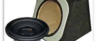
To carry out the measurement, you need to connect one of the amplifier channels, either to a speaker, if its calculated power is obviously greater, or to an equivalent load with a resistance equal to the resistance of the speaker.
As a load equivalent, you can use a PEV type resistor with a power of 10 - 100 Watts. (For a limited time, resistors of the PEV brand can dissipate power several times more than the calculated one).
An example of using the OPEV-50 resistor (8Ω, 50 Watt).
Depending on the connection diagram, you can get a load of 2, 4 or 8 ohms.
You need to apply a sinusoidal signal with a frequency of 100 - 200 Hz to the input of the amplifier (you can get by with a regular music signal) and, gradually increasing the volume, look on the oscilloscope screen at what voltage at the output of the amplifier the amplitude limitation of the output signal will begin.
When measuring maximum output power, do not apply a high frequency signal from the generator to the input of an amplifier connected to multi-way speakers, as this may lead to overload of the tweeter or midrange speaker.
The picture shows oscillograms of sinusoidal “1” and musical “2” signals. The arrow indicates the signal level that should be used when calculating power.
You can then substitute the result into the formula:
P = (U x U) : (2 x R)
P – amplifier output power in Watts,
U – output voltage of the amplifier in Volts,
R – load (speaker) resistance in Ohms.
Example:
[28 (Volts) x 28 (Volts) ] : [2 x 4 (Ohms) ] = 98 Watts
Measuring the output power of an amplifier using a voltmeter.
In the absence of an oscilloscope, to measure the output power of the amplifier, you can use any voltmeter, for example, a dial tester or a multimeter.
To do this, it is enough to assemble a simple circuit that will turn any voltmeter into a peak voltage meter.
True, then you will have to use a low-frequency master oscillator as a signal source, since with a musical signal at the input, it will not be possible to obtain reliable results.
Connection diagram.
R1 - 4 or 8 Ω (depending on speaker resistance);
VD1 - any diode for a voltage of 50 Volts and higher;
C1 - 0.47 - 1.0 µF any “dry” capacitor for a voltage of 50 Volts and higher;
PV1 - any DC voltmeter for a voltage of 50 - 100 Volts.
A sinusoidal audio frequency signal can be obtained using a software low frequency generator.
The picture shows what one of these generators looks like and what the position of its controls is when measuring power.
How to connect the linear output of a computer sound card to the input of an audio power amplifier is described here
The “Low Frequency Generator” program, which does not require installation, can be downloaded from here (archived 352KB).
How to calculate amplifier power
It so happens that the stated numbers on amplifier packaging and advertisements do not always coincide with the real ones. As a rule, they are much higher than the amplifier can actually output. All these are marketing ploys in pursuit of a bright and catchy sign. The specified parameters are obtained not entirely in good faith with great tricks, and sometimes they simply lie. In order not to fall for the tricks of advertisers, you can calculate the power of the amplifier yourself.
There is another situation in the world of car audio when the power of the amplifier is greater than indicated in the documents. But these are rare cases when the amplifier is intended for use in competitions, in which there are restrictions or gradations in the power of the systems.
In fact, calculating the power of an amplifier is quite simple. This can be done based on the rating of the installed fuses. Since you can write anything you want on the box, but no one will install a fuse larger than the maximum rating, since it will not protect the amplifier. But it is not advisable to set the value too low, as this will “strangle” the amplifier. The calculation has a certain degree of error, but for the average user it objectively estimates the rated power and can be used as a guide in choosing an amplifier, as well as in selecting a subwoofer and acoustic speakers for it.
First you need to determine the class of your amplifier in order to find out its efficiency. In car audio, classes AB and D are usually used.
Class AB. Produces a high-quality signal with an efficiency of about 50%. AB-class amplifiers are also used in head units (head units) - radio tape recorders.
Class D. Modern class of amplifiers with digital signal processing. Mainly used for subwoofers (monoblocks). D class has an efficiency of 70-80%.
See information about the class in the datasheet (documentation) of the amplifier.
Operating frequency range
The operating range is the frequency range where the gain varies within acceptable limits specified in the specifications for the amplifier. To do this, you need to build the frequency response of the amplifier. Typically this limit is set at -3 decibels. Why -3 dB? At one time it was more convenient to take into account the transmitted energy. In the -3 dB band, 50% of the signal power is transmitted.
But sometimes a slight change in gain is required. For example, at -1 dB. In this case, the operating frequency range of the amplifier will be smaller:
Active detector
The detector (half-wave rectifier) is designed to transmit signals of only one polarity to the output.
When a signal of a different polarity is applied to the detector input, the detector output level is set to 0 V. The classic circuit of an active detector using an op-amp is shown in the figure below:
When positive values of the input signal (Uin > 0) are supplied to the output, the circuit behaves as a repeater. The nonlinearity of the current-voltage characteristic of the diode and the magnitude of the forward voltage drop Upr are compensated by the OOS. When Uin < 0, Uout = 0 V.
A significant drawback of the circuit is the transition of DA1 to saturation mode when a negative voltage is applied to the input: this leads to distortion of the output signal when the input signal passes zero.
The improved op-amp active detector circuit behaves like an inverting follower when the input signal is negative. For positive values of the input signal, due to feedback through the diode VD2, a voltage equal to 2Upr is set at the output of the left one according to the op-amp circuit.
Op-amp comparator. Schmitt trigger
A comparator compares the input signal voltage with a reference voltage. The comparator circuit is an op-amp without OOS. The reference voltage in the circuit below is applied to the non-inverting input:
If the voltage at the inverting input is greater than the reference voltage, a negative saturation voltage appears at the output.
If less, then it is positive. The disadvantage of this scheme is the “edge crushing” effect: noise that appears at the moment of switching.
“Front crushing” is eliminated by introducing a small positive feedback loop (POF) into the comparator circuit. The value of resistor R1 is about 100 kOhm. The circuit has hysteresis and is called a “Schmitt trigger”:
To generate digital logic level signals, a transistor switch with an open collector (drain) is connected to the output of the comparator or Schmitt trigger.
Comparators and Schmitt triggers, including those with unipolar power supply and with level conversion, are produced by industry in a wide range. In modern development, it is advisable to use serial samples of these devices.
Finding the absolute value of the signal voltage
The absolute value (modulus) of the input signal voltage is found using an active full-wave rectifier using two op-amps:
When the input voltage is negative, diode VD1 is open and positive voltage from output DA1 is supplied to the non-inverting input DA2:
| (16) |
When the input voltage is positive, diode VD2 is open and the negative voltage from output DA1 is supplied to the inverting input DA2:
| (17) |
If the resistances of all resistors in the circuit are equal, we obtain:
| (18) |
Amplifier dynamic range
Dynamic range is the ratio of the maximum permissible output signal level to its minimum level at which a given signal-to-noise ratio is ensured:
To understand the end of the definition of “providing a given signal-to-noise ratio” of dynamic range, let's look at our figure:
Let's say our amplifier should have SNR=90 dB. Would it be correct if we take Uout min as Unoise?
Of course not! In this case, at this point on the graph, the amplitudes of the signal and noise will be equal, and therefore, according to the formula
we get that SNR=0 dB.
Disorder. This means that we need to take a value of Uout at which the equality would be observed
Let's assume that U noise = 1 μV, substitute it into the formula
From this equation we find Uout. This will just be Uout. min. for the formula:
at SNR=90. In our case, this will be point A.
We take Uout max at point B, since in this case this is the maximum value at which nonlinear distortions do not occur in our amplifier (more on them below).
The working area of the amplifier will be provided on the segment AB. In this case, we will have minimal distortion in the signal, since this region is linear. The maximum permissible output signal to noise ratio is the limit of dynamic range for an analog amplifier.
For audio amplifiers, going beyond this working area to a greater extent will be fraught with nonlinear distortions, and to a lesser extent, the useful signal will be overwhelmed by interference. Yes, you yourself probably noticed that when you turned up the volume knob of a cheap Chinese radio to the fullest, our sound quality left much to be desired, since nonlinear distortions got into the picture.
Power calculation
Power is calculated as follows:
,
where U is the voltage in the vehicle network with the engine running - 14.4 V,
I - fuse rating or the sum of ratings, if there are several A,
Efficiency - efficiency factor - AB class - 0.5 (50%); D class - 0.75 (75%),
n is the number of amplifier channels.
In other words, we find the total power taking into account efficiency and divide it by the number of channels, thereby obtaining the number of watts per channel.
Current source
The diagram below shows a stabilized current source:
The regulating input of the integrated voltage stabilizer LM317 is supplied with a voltage from the output of the op-amp, inversely proportional to the voltage drop across resistor R1. Since the voltage at the regulating input of the LM317 microcircuit should be equal to 1.25 V, the output current value is calculated using the formula:
| (19) |