This integrated speaker not only looks solid, but also provides ample opportunities for experimenting with sound. Firstly, its output stages are capable of operating in both ultralinear and triode modes. Secondly, the design allows the installation of powerful lamps of different types - KT88 or EL34. Four sound options for one model - choose any one to suit your taste and specific speaker systems. We are testing the most powerful modification on the KT88.
Save and read later -
Based on Nobu Shishido. Push-pull amplifier on KT88
https://www.lonica.org/documents/electronics/YT7890IE/2012-shishido-amplifier/ru/body.htm#P00-0100
This push-pull amplifier circuit, the input and driver stages of which are based on this sound genius Nobu Shishido (WAVAC audio lab), was invented by the famous developer of tube audio equipment Mikhail Bron, whose ideas and practical comments helped me implement this project, for which I thank him very much!
The article was corrected in 2016: errors found were corrected.
Input selector
I organized an input selector on three TAKAMISAWA relays (according to the number of inputs), which switch a low-current signal. I didn’t make a printed circuit board for the switch; I assembled everything on a breadboard.
This is the first good question to ask and answer, we will look at the advantages and disadvantages of each system. The combination is turned on, the bass is turned on and the volume can be adjusted to play. But, from my point of view, no one chooses a combo solution for high power input, for this there are two bodies that usually offer better performance at high output volumes. This solution is usually chosen for its accessibility and for the practical aspect of its proportions. Up to 300W, it is a choice within the reach of a wide audience.
The scheme is something like this:
For the sake of beauty, I installed dial indicators. The indicators are controlled by the domestic K157DA1 microcircuit. The circuit has been converted to single-pole power supply, a printed circuit board is included.
The switch, K157DA1 microcircuit and indicator backlight diodes are powered from a single stabilized voltage source.
Besides this power, the combo has its limitations due to its format, especially for our instrument. When there is less space, air is more difficult to circulate and it binds the characteristics of the speakers. High quality and powerful combos offer alternatives to this bug, but they face stiff competition from two-piece systems. Stack: Two bodies eliminate the aforementioned volume issues. You can also consider that the vibrations experienced by the amplifier and preamplifier are reduced because these components are not attached to the housing.
Content
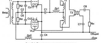
- Schematic diagram of a tube push-pull amplifier Schematic diagram of the amplifier stage
- Power supply circuit diagram
- Calculation of anode voltage rectifier
- Mechanical elements
- Placement of amplifier elements. View from above
- Standard range of metal drill diameters (mm)
Power supply for lamp UMZCH - electrical diagram
A constant current source consisting of a voltage regulator on the LM317HVT is used to stabilize the output stage current. The bias current can be adjusted by changing the current resistor setting (10-22 ohms), and this will allow you to use many different radio tubes during experiments. A switch is included for convenience and can be used to easily adjust the bias current. Lamps of type 6550, KT88, KT90 can be installed here.
Quite good quality components are used in the amplifier set. Russian-made paper-in-oil (PIO) transfer capacitor. The type is labeled K40U-9 (0.33uF/630V), which sounds good and is popular among audio enthusiasts. But feel free to experiment with various other capacitors. Resistors are carbon films. Output transformer - Edcor CXPP25-MS-8k, 25 W.
Power is supplied to the ULF through a connector located on the rear panel of the amplifier. At the 220 V input there is a 3 ampere fuse and a noise filter. Edcor power transformer with output windings 180V-0-180V at 250 mA and 12V at 4A. 12V DC power is used for filament lamps. A circuit based on LM555 and a relay is used to delay the supply of power to the anodes.
Amplifier power supply calculation
Calculation of anode voltage rectifier (Block “A”)
The transformer ME-225 from ISO Tango was chosen as the power transformer.
Rice. 3.
Transformer ME–225
with the following parameters:
Voltage on the primary winding (rms value) U1AC = 230V Nameplate voltages on the secondary windings (rms values) U2AC = 400V–360V–0–100V–360V–400V (360V taps are used to power the anode circuits). The rated current of the anode winding flowing through the 400V I2AC tap = 0.225A.
Nameplate power of the transformer (calculated based on the secondary windings):
P2 = 2 x 5.0V x 3.3A + 6.3V x 3.3A + 10V x 3.3A + 400V x 0.225A = 177VA
Calculation of power consumption of anode and filament circuits
Anode winding
quiescent current of the output lamps: 2 x 65mA = 130mA quiescent current of the driver lamp: 27mA quiescent current of the input stage: 3.8mA bias divider current of the “upper” lamp of the input stage: 2.5mA
Total quiescent current (current flowing through half of the anode winding of the transformer during half a cycle): 130 + 27 + 3.8 + 2.5 = 163.3mA (164mA).
Voltage applied to the kenotron anode during half cycle: U2AC = 360V
Power consumed from the anode winding: 2 x I2AC x U2AC = 2 x 0.164 x 360 = 118VA.
Filament windings
filament current of the GZ34 kenotron: 1.9A (two kenotrons - 3.8A) filament current of the KT88 output lamp: 1.6A (two output lamps - 3.2A) filament current of the EL38 driver lamp: 1.4A filament current of the 6J5G input lamp: 0.3A (taken into account only one “upper” lamp, since the filament of the “lower” lamp is powered from a separate transformer)
Total current of filament windings: 3.8A + 3.2A + 1.4A + 0.3A = 8.7A.
Power consumed from the filament windings: 5.0V x 3.8A + 6.3V x 3.2A + 6.3V x (1.4A + 0.3A) = 19 + 20.6 + 10.7 = 50.3VA.
Total power consumption from the secondary windings of the transformer: P2 = 118VA + 50.3VA = 168.3VA.
Features of connecting a transformer
Filament windings 0–5V 3.3A are paralleled to power the filament of 2 kenotrons.
The 0–5.0V–6.3V 3.3A winding with a 6.3V tap is used to power the filaments of the “upper” lamp of the input stage and the driver lamp. The lower terminal of this winding is connected to a voltage divider, so that half of the anode voltage of the input stage (constant bias) “raises” the filament potential of these lamps in order to eliminate the potential difference between the cathodes and filaments.
The 0–6.3V–10.0V 3.3A winding with a 6.3V tap is used to power the output lamp filaments.
Since a constant bias is not supplied to the “lower” lamp of the input stage, a separate T2 266JB6 filament transformer from Hammond is used to power the filament of the “lower” lamp, as well as the anode voltage supply delay circuit.
The measured active resistance of one half of the anode winding of the transformer = 41.3Ω (400V tap) or 37.2Ω (360V tap), the second half – 43.3Ω (400V tap), or 39Ω (360V tap) can be considered the average resistance value of half of the anode winding of the transformer RTP2 = 42.3Ω (400V tap) or 38.1Ω (360V tap).
Transformation ratio (the ratio of the number of turns of the primary winding to the secondary or the ratio of the voltage on the primary winding to the voltage on the secondary winding) for the anode winding 2 x 360V:
nP = UA / U2AC = 230V / (2 x 360V) = 0.32.
The measured resistance of the primary winding of the transformer RTP1 = 4.4Ω.
Transformer resistance reduced to the secondary winding RTP = RTP2 + RTP1 / nP = 90Ω.
Rectifier operation under static load
In the absence of an input audio signal, for the rectifier the amplifier is a static load with anode current consumed from the power source IP = 164 mA and filament current IF = 8.7 A.
Rice. 4.
Schematic diagram of a rectifier operating on a static load
Voltage drop across the anode winding of the transformer.
The consumed static current IP = 164mA flowing through half of the anode winding of a transformer with an active resistance of 90Ω / 2 will lead to a voltage drop across it equal to 0.164A x 45Ω = 7.4V. Therefore, the voltage UР supplied to the anode of the kenotron will be equal to U2AC – 7.4V = 352V.
Voltage drop across the kenotron.
It is intended to use two parallel kenotrons, so only half the current will flow through one diode, i.e. 164 mA / 2 = 82 mA. For the GZ34 lamp, it is determined from the passport data (see Fig. 5) for a current of 0.082A, the voltage drop across one diode will be 13.5V.
Rice. 5.
Anode characteristics of the GZ34 kenotron (lamp description (by Philips Data Handbook) taken from frank.pocnet)
Thus, the total voltage drop across the active resistance of half of the anode winding of the transformer and the kenotrons is ΔU = 8V + 13.5V = 21.5V.
Direct voltage applied to the anodes of the kenotron at idle speed of the rectifier UP0 = √2 x U2AC = √2 x 360V = 509V. The first filter capacitor must be charged to this voltage when there is no load.
The operating voltage of the first filter capacitor should be approximately 10% greater than the design voltage, i.e. 509 + (509 x 0.1) = 560V (600V).
Since the anode winding and the first filter capacitor are connected in series with respect to the kenotron, then at the moment of the negative half-cycle of the voltage applied to the anode (the kenotron is locked), the kenotron cathode is under the positive voltage of the first filter capacitor Uc. Thus, between the anode and cathode of the kenotron, a double amplitude voltage of the secondary winding appears (Peak Inverse Voltage) Urev = 2 x UP0 = 2 x 509 = 1018V.
The amplitude value of the voltage at the cathode of the kenotron:
UK = √2 x (U2AC – ΔU) = √2 x (360V – 21.5V) = 479V.
Amplitude of voltage ripple on capacitor C1 with a capacity of 47μF:
UC1~ = Iout / (2 x fC x C) = 0.164 / (2 x 50 x 47e–6) = 35V (p–p).
Rectified voltage on the capacitor UC1 = UC – UC1~/2 = 479 – 35/2 = 461V.
In this case, we can consider the rectifier load to be an active resistance RН = Uout / Iout = 461 / 0.164 = 2811Ω. (taking into account the active resistance of the inductor - 40Ω, the load resistance of the rectifier will become equal to 2851Ω).
Calculation of an inductive filter (Block “B”)
To further reduce ripple, an inductive filter was used (see Fig. 6), built on an LC–3–350D inductor from ISO Tango with the following parameters:
L = 3Gn. INOM = 350mA IMAX = 450mA R = 40Ω
Rice. 6.
Inductive filter
Since the inductor has active resistance, the voltage at the filter output (UC2) will be less than the input voltage (UC1) by IP x 40Ω. For a static load of 164mA, this drop will be 6.6V, so the voltage on capacitor C2 at a load current of 164mA will be 454.4V.
Filtering coefficient of the inductive filter CF = 4 x π2 x f2 x L x C2, where
f – ripple frequency of the filtered voltage (for a full-wave rectifier circuit, the ripple frequency is 100 Hz). L – inductance of the inductor, H. C is the capacitance of the capacitor (C2) next to the inductor, F. shows how many times the ripple voltage at the filter output is less than the ripple voltage at the filter input, i.e. CF = UC1~ / UC2~.
Thus, for the selected capacitor C2 = 470μF, CF = 4 x π2 x 1002 x 3 x 470e–6 = 556.6 and the ripple voltage at the filter output UC2~ = UC1~ / CF = 35 / 556.6 = 0.063Vp–p.
The operating voltage of the capacitor at the inductor output due to the insignificant ripple voltage can be selected to be approximately 5% higher than the filter output voltage = 454.4V + 0.05 x 454.4V = 477V (it seems possible to use a capacitor with a standard operating voltage of 550V).
Additional ripple filtering can be achieved with a plug filter consisting of inductor L1 and capacitor C3 connected in parallel to it. If the input and output of the filter choke are shunted with a capacitor, then a parallel resonant circuit (current resonance) will be obtained, which has maximum resistance for the resonant frequency. Such a circuit can be calculated for a resonant frequency of 100 Hz based on the following condition:
Current resonance condition: YC = YL (where Y is conductivity) whence ωC = 1/ωL, whence ω = 1/√(LC). Given that ω = 2πf, we obtain f (100 Hz) = 1/(2π√(LC)). For a 3 H choke inductance, the value of the shunt capacitance will be equal to: Csh = 1/(L x (2 x π xf)2) = 1/(3 x ((2π x 100)2)) = 0.844μF (standard value 0.82μF is selected ).
Minimum value of current flowing through the inductor: IMIN = 2 x √2 x UC2 / (6 x π2 xfx L) = 2 x √2 x 461V / (6 x π2 x 100 x 3) = 73mA. If the amount of current consumed by the load is less than this minimum permissible value, then the smoothing capacitor connected after the inductor will be charged by voltage pulses to the amplitude voltage value at the kenotron cathode under load (i.e. up to 479V).
Calculation of quenching resistors for anode voltages of amplifier stages (Block “B”)
The calculated value of the anode voltage of the output stage of the amplifier UB1 = 452V at a current IB1 = 130mA.
The set value of the anode voltage of the driver stage of the amplifier is UB2 = 320V at a current IB3 = 27mA, so the value of the damping resistor will be equal to (UB1 – UB2) / (27mA + 4mA + 3mA) = 3.9kΩ. The power dissipation across this resistor will be (UB1 – UB2) x (27mA + 4mA + 3mA) = 4.5W
The specified value of the anode voltage of the amplifier input stage is UB3 = 250V at a current IB3 = 4mA, so the value of the quenching resistor will be equal to (UB2 – UB3) / (4mA + 3mA) = 10kΩ. The power dissipation across this resistor will be (UB2 – UB3) x (4mA + 3mA) = 0.5W
The specified current value through the bias voltage divider is I = 3mA, so the total resistance of the divider will be equal to UB3 / 3mA = 83kΩ.
Calculation of the anode voltage supply delay circuit (Block “C”)
The time constant of the delay circuit is τ = C x (R1 x R2 / (R1 + R2)).
at values C = 100μF, R1 = 470kΩ, R2 = 680kΩ we have τ = 28 seconds.
Calculation of a fixed grid bias rectifier (Block “D”)
Range of changes UBIAS = {–35 … –70}V, i.e. The voltage drop across the grid bias resistor will be 30V.
Input alternating voltage of the rectifier U~ = 100V.
Rectified voltage U= = √2 x 100V – U diode = 141V – 1.0V = 140V.
Rectified voltage filter resistor RF = 10kΩ.
The total current of the two dividers is I0 = 6mA, so the drop across the filter resistor UR = 10kΩ x 6mA = 60V.
Thus, the voltage supplied to the two dividers is U0 = √2 x 100V – Udiode – UR = 141 – 1.0 – 60 = 80V, and the total resistance of one divider is R = U0 / (I0 / 2) = 80V / 3mA = 27kΩ.
Current through each divider I1 = I2 = 6mA / 2 = 3mA.
The lower divider resistor in the circuit is selected from the condition of limiting the lower value of the bias voltage –35V: 35V / 3mA = 11.7 kΩ (the standard value of 12 kΩ is used, while the lower value of the bias voltage will be –36V).
The divider potentiometer must provide a voltage change from 36V to 70V, so the voltage drop across it will be 70V – 36V = 34V, which at a current of 3mA will determine its resistance to be 34V / 3mA = 11.3kΩ. (a 10kΩ potentiometer was used, and the grid bias voltage adjustment range was 10kΩ x 3mA = 30V).
The top divider resistor in the diagram is 27kΩ – (12kΩ + 10kΩ) = 5kΩ (the standard value of 5.1kΩ is selected).
The power dissipated in the resistance of the RF filter will be 10kΩ x 6mA2 = 0.36W.
SOCIAL INTEGRATION
At first glance at the amplifier, it may seem that this is one of the crafts from Aliexpress - there are a lot of similar ones and they are offered almost for the price of scrap metal. In fact, Cayin is a serious company that produces a wide range of audio equipment from portable players to streamers, DACs and CD players. And these modern advanced devices are by no means entry-level. These include, for example, the N8 portable Hi-Fi player, capable of playing files with resolutions up to 32-bit/384 kHz and DSD256.
There are tube amplifiers in the Cayin catalog for every taste and budget, and our test subject, the CS-55A integrated amplifier, is priced approximately in the middle of the model range. It is available with different output tubes - EL34 and KT88, their type is indicated in the model name. We have the second, more solid option, although you can use any of them if you wish - there is a special switch on the rear panel. This is a very useful option, because... the mentioned pentodes differ not only in power, but also in their sound character. “Thirty-fours” are a classic for Marshall guitar amps; they were also used in the iconic Dynaco and Marantz amplifiers. The potbellied KT88s and their leaner 6550 clones arrived later, and with 46W at the anode, they quickly became popular with amp designers and heavy metal fans alike for their ability to maintain high intelligibility on dense spectrum music.
The Cayin CS-55A (KT88) output tubes can also be switched from triode to ultra-linear mode. The latter allows you to get more power (2 x 40 W versus 2 x 22 W in a triode) with minimal consequences for sound quality. In a triode, the harmonic spectrum of the output tubes is shorter, so the sound subjectively seems more transparent. The current of the lamps is regulated by trimming resistors located under the slot on the top panel of the amplifier. There is also a round device for its control. The output stage modes are stable: during three hours of listening, the needle did not leave the zone of optimal values.
The KT88 uses dual 12AU7 (ECC82) triodes for phase separation and drive, and a pair of 12AX7 (ECC83) for preamplifier. All lamps have the Cayin logo. Transformers, including broadband outputs, are wound on Sh-cores.
The amplifier has an MM corrector with a standard gain of 40 dB. Most likely, it is semiconductor, because... There are not enough tube stages (and you need at least two of them for each channel). Moreover, there is a low-voltage power supply in the circuit - for the built-in DAC.
I mentioned the Cayin N8 portable player with PCM 32/384 support for a reason: apparently, the amplifier uses the same chipset with the AK4497EQ converter, which, by the way, is used to build very advanced High-End DACs. The digital board has one input – asynchronous USB 2.0.
In addition to the vinyl player, the amplifier can connect two sources with line outputs. There are three acoustic terminals in each channel - “zero” and separate for matching with 4 and 8 ohm loads. On the front there is a headphone output with a 6.3 mm jack.
The amplifier is assembled on a steel chassis with a thick aluminum front panel, which can be silver or black. The lamps are covered with a lattice casing, the transformers are covered with rectangular screens. The desired volume is set by a motorized potentiometer, while the position of the regulator is monitored by a luminous mark on its end. On the right is an input selector and a line of LEDs with their designations.
The remote control is a solid aluminum one, from which, in addition to adjusting the volume and selecting a source, you can switch the modes of the TR/UL output lamps.
The first test is through the Phono input with a Marantz TT-15S1 turntable. The amplifier's corrector is quite hi-fi, with an even tonal balance, dense bass and a light, transparent top. The lower middle is slightly accentuated, but this is typical for most turntables with a not too massive table. The main thing is that the sound of the amplifier did not have that sweet vintage quality that Chinese tube crafts are guilty of. The sound is collected, fast, dynamic, with a lot of musical details. No loose bass, boom or soporific sluggish presentation. A suitable option for authentic reproduction of records, both archival and new ones.
Now let's listen to the amplifier from the line input by connecting the Atoll MD100 CD player. First - with a solid floor-standing acoustics Arslab Old School Stark. In the triode, the sound turned out to be melodious, detailed, with a rich spectrum and extremely distinct bass. High detail did not cause discomfort, since the nuances were not enlarged or protruded. The delicacy of the tweeters was also evident, as they perfectly conveyed not only the dense cloud created by the cymbals, but also light individual touches to them.
Damping is moderately free: the 12-inch bass diffusers behaved quite relaxed on sharp impacts and fast rolls, but without long-term inertial oscillations after the attack. The amplifier does not have too deep feedback, only to slightly reduce the output impedance - the bass notes are clear, full, and not “dry”. The overall dynamics are impressive even in a triode, incl. and thanks to the high sensitivity of Old School Stark. Indeed, KT88, with maximum sound saturation, is capable of preserving the timbral features of individual instruments. In pentode mode, playback becomes a little harder, more assertive, perhaps even a little rougher, but clearly more emotional.
We assessed the ability to organize space with Old School Monitor m1 shelf holders. They have a coaxial head installed, the nature of the radiation is close to a point source. With them, the scene turns out to be quite compact, but extremely clear with sharp localization of virtual sources even at the edges. In relation to an amplifier, this means phase matching of the channels, which, in turn, indicates complete identity of the output transformers.
The last stage of testing is the evaluation of the built-in DAC. The MacBook Pro with the Amarra 4 Luxe player was also loaded with rips of the discs that we played a little earlier on the CD player. When directly comparing the two, the difference was usually in the volume level. The qualitative differences boiled down to a slightly flatter stage when decoding files and some formality in the transmission of the highest overtones. But the differences are so insignificant that they can only be noticed by specially listening. It was generally difficult to find fault with the high-res; here, everything was in order with the stage, both with the upper range and with the filling of the lower register.
But in general, the CS-55A (KT88), with a phono stage and a DAC implemented at a real hi-fi level, can be a good option for a music lover with broad needs. Or for a whole family, in which everyone has their own ideas about how and on what they should listen to music. And such an opportunity, especially for quite reasonable money, is rarely provided in our time.
- COMPONENTS
- Sources: Marantz TT-15S1 vinyl player, Atoll MD100 CD player,
- MacBook Pro laptop with Amarra 4 Luxe player
- Speaker systems: Old School Stark, Old School Monitor m1
- Cables: InAkustik Referenz High Speed USB 2.0, Studio Connections Reference Plus
- MUSIC
- Vinyl: Ella & Oscar. Pablo Records, 1976
- Creedence Claerwater Revival, "Cosmo's Factory". Liberty, USA 1970
- Tchaikovsky, "The Nutcracker". 2LP, CBS, 1979
- Wishbone Ash, "Just Testing". MCA Records, 1979
- Dali, “In Admiration of Music. Volume 4". Dali CD, 2015
Calculation of the output stage
Since the output stage is connected according to an ultra-linear circuit to a transformer with known parameters - XE-60-5 from ISO Tango, the calculation will be reduced to determining the quiescent current and power dissipation of the stage.
Rice. 7.
Graphic calculation of the operating mode of the KT88 lamp in a push-pull output stage (description of the lamp (by The General Electric CO. LTD of England) taken from the website frank.pocnet)
The first point of the load line IA (UA = 0) = EA / RA, where RA is determined by the specified resistance RA–A of the Tango XE-60–5 output transformer (5kΩ), recalculated for one arm: RA = RA–A / 4 = 1.250 kΩ. Then IA (UA = 0) = 452 / 1.250 = 362mA.
The second point of the load line UA(IA = 0) = EA = 452V.
Point “P” will be determined at the intersection of the load line with the characteristic at UC = 0, while IA max = 328mA, UA min = 42V.
The quiescent current of the lamp IA0 = ~(1/3 ... 1/5) IA max / 2 = 65 mA (point “T”) is located at the intersection of the load line with the characteristic at UC approximately equal to -43V this will be the bias voltage of the lamp in idle mode .
Point “T” determines the voltage on the anode in idle mode UА0 = 370V, corresponding to the quiescent current of the lamp IА0.
Resistance in the anode circuit of two lamps: RA–A = 22 x (UA0 – UA min) / (IA max – IA0) = 4 x (370 – 42) / (0.328 – 0.065) = 5 kΩ.
Anode power dissipation PA = UA0 x IA0 < PA max = 370 x 0.065 = 24W < 40W.
Maximum power supplied by two lamps to the load with an ultra-linear cascade efficiency of ~60%: P~ = (IA max x (UA0 – UA min) x η) / 2 = (0.328 x (370 – 42) x 0.60) / 2 = 32W .
Amplitude of the alternating component of the lamp anode current: ImA = (IA max – IA0) / 2 = (328 – 65) / 2 = 132mA.
Effective value of the lamp anode current at maximum power: IА0 max = (IA max + 2 x IА0) / 4 = (328 + 2 x 65) / 4 = 115 mA.
The effective value of the anode current in the common wire of the output transformer Imax = 2 x IA0 max = 230 mA.
Rice. 8.
Construction of the grid characteristic of one KT88 lamp of a push-pull output stage (description of the lamp (by The General Electric CO. LTD of England) taken from the website frank.pocnet)
A feature of this cascade is the feedback supplied from the output transformer to the cathodes of the lamps (the so-called “supertriode” connection). You can read more about this scheme on Menno van der Veen's website.
Cayin CS-100A (KT88)
Inputs: 3 x RCA, Pre-In RCA Impedance for linear/Phono inputs: 100 kOhm Sensitivity: 430 mV line/1.3 V Pre-In Output power: in triode mode 2 x 50 W, in pentode (ultralinear) 2 x 80 W Harmonic distortion: 1% (1 kHz) Amplified frequency band: 8 - 75,000 Hz Signal-to-noise ratio: 92 dB Outputs: 2 x RCA for subwoofers, 6 screw terminals Remote control: yes Power consumption: 480 VA Dimensions: 420 x 200 x 394 mm Weight: 30 kg
Prepared based on materials from the AudioVideo Salon portal, June 2020
www.salonav.com This review was read 4,670 times
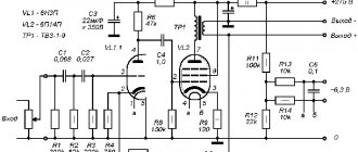
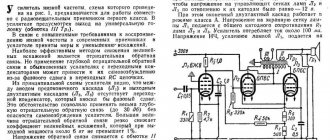
Calculation of the input stage
The input stage is made according to the circuit of a parallel-controlled two-tube amplifier (SRPP).
Rice. 9.
Schematic diagram of the input stage
Rice. 10.
Family of anode characteristics of the 6J5G lamp (lamp description (by RCA) taken from frank.pocnet)
With a given quiescent current of 4mA through the lower lamp, we obtain the voltage on the lamp grid = 4V, then the automatic bias resistance in the cathode circuit of the lower (as well as upper) lamp = 4V/4mA = 1kΩ.
The gain of the cascade, provided that the same lamps are used as the “upper” and “lower”, and also that the cathode resistor of the lower lamp is shunted by a capacitor:
A = μ x (rA2 + RK2 x (μ + 1)) / (rA1 + rA2 + RK2 x (μ + 1)) = 20 x (8000 + 1000 x (20 + 1)) / (8000 + 8000 + 1000 x (20 + 1)) = 15.7.
Where:
rA1 – internal resistance of the “lower” lamp rA2 – internal resistance of the “upper” lamp RK2 – bias resistance in the cathode circuit of the “upper” lamp
μ – lamp gain
The amplifier is designed for a nominal input voltage of the audio signal ~1.0VP–P; therefore, at this signal level, the output voltage of the cascade will be 1.0 x 15.7 = 15.7VP–P. Since the connection between the input and driver stages is direct, the voltage value on the grid of the driver lamp will be UC + 15.7/2 = 125 + 7.85 = 133V.
Amplifier circuit
I chose the scheme “according to Manakov”:
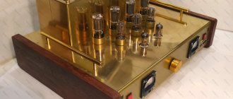
I started, as always, by assembling the case. I will not dwell in detail on the technology of its manufacture; I talked about this in detail in As always, I assembled the amplifier on a separate metal chassis mounted inside the case on racks. This allows you to minimize the number of holes in the top cover of the amplifier. To make the case, I used an aluminum corner 20x20x2.0, duralumin sheets, 1.5 mm thick (for the top cover) and 1 mm (for the bottom cover and chassis). The paneling is made of beech, painted with stain and varnish in several layers. Dural is spray painted. This time I used ready-made caps for transformers, having ordered them in advance.
In addition to different amplification classes, the components that generate power may vary. From tubes to transistors, manufacturers offer different solutions for varying and more or less questionable costs and benefits. Finally, the bass players we have can have a bi-amplification system. This does not mean that their amplifier has turned into sails and steam, but it does mean that the signal coming out of the amplifier is split into two parts thanks to a crossover filter that sends them to different speakers. will be able to distribute high frequencies and bass on one body or another in accordance with their specifics.
All mechanical work was performed on the balcony. I used a folding workbench, a drill, an electric jigsaw, a disc sander, a hand router, a Dremel and a professional miter box. Over the years of amateur radio, I have acquired a lot of good instruments. This allows me to complete many complex jobs much faster and more accurately. But most of this work can be done manually. With more effort and time, of course.
Cabinet: Also known as a cabinet or baffle, this is the last link in your audio chain. Consists of one or more loudspeakers and a consolidated structure. Typically ranging from eight to eighteen inches, the configurations we're interested in tend to focus on fifteen inches, 10 inches, and twelve inches. Their role is to generate sound from the electrical signal coming out of the amplifier through a simple process: a magnet, serving as a continuous magnetic field generator, moves a copper coil depending on the voltage of the current flowing through it, the coil is attached to a membrane, its movement causes the latter to vibrate, creating sound.
Radio components, in general, are the most common. I used capacitors K78-2 and K71-7 as isolation capacitors, everything else was a “hodgepodge”.
I bought EL34 lamps already selected in the “four”.
The larger the diameter of the bowl, the wider the vibrating surface and wider movements to correctly reproduce low frequencies. So we'll look at fifteen inches as the boomer, ten inches and twelve as the mid speakers, and the bottom ones for the tweeters. Another type of loudspeaker that specializes in reproducing high frequencies and is often found on the front panel of our amplifiers: the tweeter. Cone tweeters, high-frequency tweeters and piezo tweeters are available.
The choice of loudspeaker(s) is not limited by their size, but also by their design: the type of magnet used on the membrane, the rendering will not be the same depending on the nature of these elements. Initially, our speakers only had a large fifteen-inch boomer that took up most of the low frequencies, but manufacturers soon offered multi-bowl configurations. Its main function is to direct sound waves, first to the facade and especially inside its walls. Because the loudspeaker also reproduces the sound wave backwards, and it is very important that this wave does not interfere with the projection onto the façade.
Power transformer: torus, 270Vx0.6A - anode secondary, 50Vx0.1A - bias secondary, 2x6.3x4A - for filament power supply.
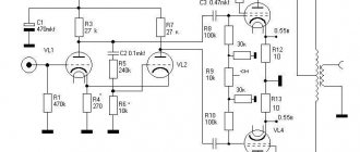
Driver cascade calculation
As noted earlier, the bias voltage UC of the driver tube (drop across the cathode resistor) must be at least 133V. With the selected anode current of the driver lamp IА0 = 27 mA, the cathode resistance of the driver lamp RК = 133/27 = 5 kΩ. The power released by this resistor PRK = UC x IA0 = 133V x 0.027mA = 3.6W.
Rice. eleven.
Schematic diagram of the driver stage
An NC-14 transformer from ISO Tango was chosen as an intermediate transformer. The total resistance of the parallel-connected anode windings of the transformer is 1.25 kΩ (active resistance 82.5 Ω), the permissible current is 30 mA. The total resistance of the series-connected anode windings of this transformer is 5 kΩ (0.33 kΩ), the permissible current is 15 mA.
Rice. 12.
Transformer NC–14
The constant voltage on the grid of the driver lamp in quiescent mode is UC0 = 125V, the resistance in the cathode circuit of the driver lamp is RК = 5 kΩ (bias voltage at the selected quiescent current IА0 = 27 mA, UC = 133V), so there is a constant bias voltage on the lamp grid relative to the cathode UC =125 – 133 = –8V (lamp operating point).
The anode load line (see Fig. 13) for direct current, which determines the division of the anode voltage between the lamp (Ri) and the resistances in the anode (RA) and cathode (RK) circuits, is constructed based on the following considerations: If the anode current is zero, then the voltage at the anode of the lamp is equal to the source voltage EA = 320 V. If the voltage drop across the lamp is zero, then the current through the lamp is limited by the value IAmax = EA/(RA + RK). At a given RA = 0.0825 kΩ (active resistance of the parallel-connected anode windings of the transformer) and RК = 5.0 kΩ, the approximate value of the maximum current IАmax = 320 / (0.0825 + 5.0) = 63 mA.
Rice. 13.
Family of anode characteristics of the EL38 lamp in triode connection (by Tom Schlangen)
I made some changes to the diagram
Instead of a 6N9S lamp, I first arrogantly tried to use a 6N2P (EV). The result was... a “dead” sound. Not that! Not at all. And the holes for the panels are drilled, and the chassis is already installed. What to do? I started looking for a replacement for this lamp. It turned out that the ECC85 lamp (according to reviews from colleagues on the forums) is “very good.” I bought a pair. Changed the values of the “piping” resistors. The anodes have 36 kOhm (2W), the cathode resistors have 180 Ohm, and the bias is about 1.5 V. I’ll say right away that this has greatly benefited the sound!
Thus, the shell volume envelops this wave, resulting in acoustic pressure. This is done using internal panels and acoustic wool. The principle is simple, one returns the acoustic pressure to the façade with one or more ventilation openings. This is why subwoofers have large holes. These latter have no flap, no annoying jokes from your beloved pet.
To sum things up in one sentence, the preamplifier senses the signal, the amplifier provides the electrical power, and the speaker disperses the volume. A preamplifier, power amplifier and loudspeaker can be used in a combined version, this will be called a "combo". But it is also possible to play on an amp head separated from the speakers and then "stacked". Some brands even offer preamps independent of their amp.
Amplifier Parts List
Mechanical elements
Chassis: Hammond Chassis Walnut
| P-HWCHAS1310AL | 2 pcs | |
| Hammond Bottom Panel | P-HHW1310ALPL | 2 pcs |
| Mounting panels (distance between blades - 9.525 mm): | ||
| 47.6 mm 6 petals | P-0602H | 10 pieces |
| 57.2 mm 7 petals | P-0702H | 10 pieces |
| 66.6 mm 8 petals | P-0802H | 10 pieces |
| Clamps for electrolytic capacitors MPSA 35 – 50 mm | MUNDORF-75217 | 6 pcs |
| Bias Voltage Regulator Knobs | P-K310 | 4 things |
| Lamp sockets (CNC) | 14pcs | |
| Rack | M4 30mm FF | 8 pcs |
| Rack | M4 10mm MF | 16 pcs |
| Rack | M3 10mm MF | 8 pcs |
| Rack | M3 10mm FF | 8 pcs |
| Screw | M4 x 6mm | 100 pieces |
| Screw, countersunk head | M4 x 6mm | 100 pieces |
| Screw | M3 x 6mm | 100 pieces |
| Screw, countersunk head | M3 x 20mm | 100 pieces |
| Lock washer | 100 pieces | |
| Lock washer | 100 pieces | |
| Washer | 100 pieces | |
| Washer | 100 pieces | |
| screw | 100 pieces | |
| screw | 100 pieces | |
| Aluminum sheet 2.3 mm | 304 mm x 914 mm | 1 PC |
Electromechanical elements
| Single-core insulated installation wire | 21.5 AWG | 1 reel |
| Single-core insulated installation wire | 16.5 AWG | 1 reel |
| Teflon insulation internal ø 1.5mm external ø 1.8mm | 7.5m | |
| Speaker terminals (long) | 12 pcs | |
| RCA connectors type “D” (inputs) | NF2D-B-0 | 2 pcs |
| Anode voltage terminal (Pomona) | 2142-0 | 2 pcs |
| Anode voltage plug (Pomona) | 3690-0 | 2 pcs |
| Anode Cap (Yamamoto Plate Caps) 6mm | 320-070-91 | 2 pcs |
| Pointer indicator (Yamamoto Precision Panel Meter) 100mA | 320-059-18 | 2 pcs |
| Mains connector (IEC) + fuse | 2 pcs | |
| Power switch (Nikkai) | 2 pcs | |
| Switch for measuring the quiescent current of the final stage (Nikkai) | 2 pcs |
Electronics
| Power Transformer (Tango) | ME–225 | 2 pcs |
| Filament transformer (Hammond) | 266JB6 | 2 pcs |
| Power Choke (Tango) | LC–3–350D | 2 pcs |
| Intermediate transformer (Tango) | NC–14 | 2 pcs |
| Output Transformer (Tango) | XE–60–5 | 2 pcs |
| Kenotron | GZ-34 | 4 things |
| Lamp (GEC) | 6J5GT | 4 things |
| Lamp (Mullard) | EL38 | 2 pcs |
| Lamp (Gold Lion) | KT88 | 4 things |
| Electrolytic capacitor, Mundorf, M-TubeCap | 47μF x 600V | 2 pcs |
| Electrolytic capacitor, Mundorf, M-Lytic HV | 470μF x 550V | 2 pcs |
| Electrolytic capacitor, Mundorf, M-Lytic MLSL HV | 100μF + 100μF x 500V | 2 pcs |
| Quenching resistor, Mills, MRA–12 | 20kΩ 12W | 4 things |
| Quenching resistor, Mills, MRA–12 | 3.9kΩ 12W | 2 pcs |
| Quenching resistor, Mills, MRA–5 | 10kΩ 5W | 2 pcs |
| Electrolytic capacitor, Elna Silmic II | 100uF 16V | 2 pcs |
| Electrolytic capacitor, Elna Silmic II | 470 uF 25 V | 2 pcs |
| Electrolytic capacitor, Elna Silmic II | 100uF 100V | 4 things |
| Anode voltage delay relay (Panasonic) | HC2-H-DC6V-F | 2 pcs |
Amplifier settings
Here I fully quote Manakov:
The first stage is adjusted by a drop in DC voltage of 1.8-2 V at the control point on the cathode resistor by selecting the value of this resistor. The second stage is adjusted by the DC voltage drop at the control points on the cathode resistors of the 1 Ohm lamps of the output stage, by adjusting the bias voltage on the control grids of these lamps. The voltage drop across them should be 0.035-0.04 V, which corresponds to an anode current of each lamp of 35-40 mA. The most “economical” ones can reduce the currents of the output lamps to 25-30 mA. I think it is unnecessary to remind you that all these settings need to be made in silent mode. By alternating voltage, the phase inversion stage is adjusted by applying an alternating voltage of about 0.5 V with a frequency of 3 kHz to the grid of the left triode of the 6N9S lamp; a trimming resistor in the grid circuit of the right triode of the lamp sets the same alternating voltage on the anodes of the lamp. In this case, you need to use a voltmeter with an input resistance of at least 1 megohm.
Defects of a two-particle solution: its price, as a rule, is higher and more voluminous; the dimensions of independent caissons are slightly increased. There are, however, independent boxes of smaller volume and weight with the same characteristics. These are all problems with modern technologies, such as the neodymium magnet that is increasingly equipped in our loudspeakers or the use of isobaric housing, to mention just these two solutions.
It is difficult for me to provide a solution to each of your personal needs, and this article is not intended to promote a specific brand or model. This way you will learn how to choose your gain according to the elements described earlier. The difficult part will be to combine all these qualities into one combo if you choose this amplification solution, however, you will need to evaluate its components separately. The choice of preamp should suit your taste in terms of its definition.
I will only add that when using EL34 lamps, the quiescent currents can (and should!) be safely raised to approximately 56 - 60 mA, with an anode voltage of about 350 V.
Mechanical drawings
Placement of amplifier elements. View from above
Rice. 14.
Placement of amplifier elements. View from above
Dimensions and placement of amplifier elements. Back view
Rice. 15.
Dimensions and placement of amplifier elements. Back view
Top mounting panel
Rice. 16.
Top mounting panel
The bottom panel. Ventilation holes
Rice. 17.
The bottom panel. Ventilation holes
Location of power supply parts. View from above
Rice. 18.
Location of power supply parts. View from above
Location of power supply parts. Side view
Rice. 19.
Location of power supply parts. Side view
Internal mounting panels
Rice. 20.
Internal mounting panels
Mounting panel of the amplifier part
Rice. 21.
Mounting panel of the amplifier part
Partition
Rice. 22.
Partition
Filament transformer mounting panel
Rice. 23.
Filament transformer mounting panel
Rectifier mounting panel
Rice. 24.
Rectifier mounting panel
Gallery
Several photos from different stages of amplifier construction.
Rice. thirty.
Power transformer
Rice. 31.
Power and filament transformers assembled
Rice. 32.
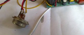
Throttle and kenotron sockets assembled
Rice. 33.
Glow circuit routing
Rice. 34.
Amplifier housing
Rice. 35.
Amplifier, top view
Rice. 36.
Amplifier from the inside
Rice. 37.
Amplifier with installed tubes, top view
From the assembly features
The most important thing is the distribution of land.
It can be clearly seen that I organized two ground points, collected the grounds of the left and right channels on them and connected them to the “minus” of the anode voltage filter capacitor. As a result, together with the “electronic throttle”, this gave a very good effect. I can't hear the background at all. Not 10, not 5, not 2 centimeters from the speaker. But the main quality of the two-body solution is its modularity. You can buy an amp head and change its distribution to suit your needs. Unlike a combo, there's nothing stopping you from changing speakers or amps if one or the other no longer suits you.
So the two bodies offer superior credentials for a combined solution and an alternative to purchasing a complete system when your needs change. Some heads can even work without speakers, so they can be used separately for recording without the need to push a speaker into the studio. In most cases, the head must be connected to a cabinet to avoid overheating and transforming into makeshift smoke.
Notes
Standard range of metal drill diameters (mm)
1, 1.5, 2, 2.5, 3, 3.3, 3.5, 4, 4.1, 4.2, 4.5, 5.0, 5.5, 6, 6.5, 7, 7.5, 8, 8.5, 9, 9.5, 10, 10.5, 11, 12, 12.5, 13
How to read inch screw sizes
For example: #4–40 1/4″.
The first digit is the number corresponding to the diameter of the screw (diameter = “#” x 0.013″ + 0.060″). The second number is the thread pitch (number of threads per inch): 25.4 / 40 turns = 0.635. The third number is the length of the screw: 1/4″ = 6.35 mm.
Some correspondence between the screw number and its diameter are shown in the table.
| Screw no. | diameter (inch) | diameter (mm) |
| #0 | 0.0600″ | 1.5240 mm |
| #1 | 0.0730″ | 1.8542 mm |
| #2 | 0.0860″ | 2.1844 mm |
| #3 | 0.0990″ | 2.5146 mm |
| #4 | 0.1120″ | 2.8448 mm |
| #5 | 0.1250″ | 3.1750 mm |
| #6 | 0.1380″ | 3.5052 mm |
| #8 | 0.1640″ | 4.1656 mm |
| #10 | 0.1900″ | 4.8260 mm |
| #12 | 0.2160″ | 5.4864 mm |
Table 1.
Some correspondence between the screw number and its diameter
Correspondence between American and European wire diameter records
| American Wire Gauge (AWG) | Diameter (inches) | Diameter (mm) | Sectional area (mm2) |
| 0000 | 0.46 | 11.68 | 107.16 |
| 000 | 0.4096 | 10.40 | 84.97 |
| 00 | 0.3648 | 9.27 | 67.40 |
| 0 | 0.3249 | 8.25 | 53.46 |
| 1 | 0.2893 | 7.35 | 42.39 |
| 2 | 0.2576 | 6.54 | 33.61 |
| 3 | 0.2294 | 5.83 | 26.65 |
| 4 | 0.2043 | 5.19 | 21.14 |
| 5 | 0.1819 | 4.62 | 16.76 |
| 6 | 0.162 | 4.11 | 13.29 |
| 7 | 0.1443 | 3.67 | 10.55 |
| 8 | 0.1285 | 3.26 | 8.36 |
| 9 | 0.1144 | 2.91 | 6.63 |
| 10 | 0.1019 | 2.59 | 5.26 |
| 11 | 0.0907 | 2.30 | 4.17 |
| 12 | 0.0808 | 2.05 | 3.31 |
| 13 | 0.072 | 1.83 | 2.63 |
| 14 | 0.0641 | 1.63 | 2.08 |
| 15 | 0.0571 | 1.45 | 1.65 |
| 16 | 0.0508 | 1.29 | 1.31 |
| 17 | 0.0453 | 1.15 | 1.04 |
| 18 | 0.0403 | 1.02 | 0.82 |
| 19 | 0.0359 | 0.91 | 0.65 |
| 20 | 0.032 | 0.81 | 0.52 |
| 21 | 0.0285 | 0.72 | 0.41 |
| 22 | 0.0254 | 0.65 | 0.33 |
| 23 | 0.0226 | 0.57 | 0.26 |
| 24 | 0.0201 | 0.51 | 0.20 |
| 25 | 0.0179 | 0.45 | 0.16 |
| 26 | 0.0159 | 0.40 | 0.13 |