The most interesting videos on Youtube
Other articles devoted to the construction of this ULF.
How to calculate and wind a low-frequency power transformer for a ULF power supply? FAQ.
Homemade amplifier and speakers for a computer, player or mobile phone from available parts. ULF, part 1.
Power supply for low frequency amplifier from available parts. ULF, part 3.
Electronic volume, stereo and tone control unit. ULF, part 4.
Block of low frequency final amplifiers. ULF, part 5.
Simple technologies for processing plastic and metal. ULF, part 6.
Final assembly, adjustment and testing. ULF, part 7.
What are the advantages of electronic regulators over mechanical ones?
The main advantage of using a block of electronic regulators is that there is no need to search for potentiometers with different transfer characteristics, but the same standard sizes.
Dual potentiometers.
- Potentiometer type SP3-4.
- Imported potentiometer.
- Potentiometer SP3-33-24 with loudness compensation output.
For example, a volume control would require a dual potentiometer with an inverse logarithmic response, and a stereo control would require a dual potentiometer with a linear response.
The search for a dual potentiometer with taps to organize loudness compensation might not be successful at all.
And when electronically adjusting the signal, variable resistors with a linear dependence can be used for all regulators. The microcircuit itself will generate the necessary transfer characteristic required for each regulator.
Electronic regulators not only simplify the search and selection of components, but also eliminate the problem of the so-called “rustling” of potentiometers.
Power supply
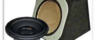
The power supply is transformer based on a low-frequency power transformer T1 type 109-01AF11-01. It has a primary winding of 220V, a secondary winding of 26V and a current of 2.2A with a tap from the middle part. The tap forms the midpoint (GND).
Since there is a tap from the center of the secondary winding, it was decided to make the rectifier circuit using a full-wave circuit using two diodes VD1 and VD2.
Rice. 2. Schematic diagram of the power supply for a homemade low-frequency amplifier on the TDA2003.
The source is not stabilized. You can use another transformer with similar parameters. If there is one 11-13V winding, the rectifier circuit will need to be made as a bridge with four diodes. It can also be powered from a ready-made source, with a constant voltage of 12-18V at a current of at least 2 A, for example, from a power supply for some computer peripherals or office equipment.
Selection of potentiometers.
High-quality linear potentiometers were often used in industrial equipment of the past, but their use in audio equipment was limited precisely because of the lack of non-linear variable resistors. Now such potentiometers can be bought very inexpensively on any radio market at a price of 0.1... 0.3 $.
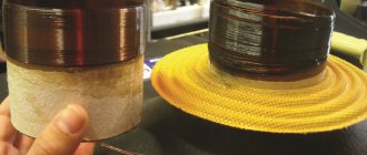
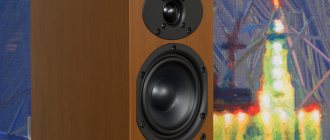
For the regulators, I selected potentiometers of the SP4-1 type, since, despite their relatively small sizes, they have proven themselves to be quite reliable products.
The shaft diameter of the selected resistors is 3mm, and the nominal value is 100kOhm.
In the nominal range from 22 to 100 kOhm, I removed the frequency response of the regulator block and did not notice any deviations.
It would be possible to completely abandon potentiometers, but then the control would not be so efficient, and there would be a need for at least some indication of the position of the regulators.
So, I settled on the simplest, combined electronic regulator, combining the advantages of electronic regulators and the convenience of mechanical ones.
Chip TDA1524A.
The regulator unit is developed based on the TDA1524A microcircuit. The choice fell on it simply because it turned out to be one of the microcircuits that required minimal wiring, and it was possible to purchase it on the local market at a reasonable, although, in my opinion, slightly inflated price, which amounted to $2.
The TDA1524 microcircuit can be powered from a voltage of 7.5 to 16.5 V, with a current consumption of 15... 56 mA.
The adjustment range for high frequencies is: –15… +15dB (±3dB), and for low frequencies: –19… +17dB (±3dB).
Volume control circuit on the TA8119P chip
These are the TA8119R chips from TOSHIBA (Fig. 1) and VAZ520 from POHM (Fig. 2). As can be seen from the figures, they differ only in the number of pins, and their electrical characteristics are almost the same. By the way, the TA8119 IC is available only in a DIP package for through-hole mounting. and BA3520 - in DIP and SOIC packages (BA3520 and BA3520F, respectively, the latter for surface mounting). The distance between the rows of pins for the TA8119 and the SOIC version of the BA3520F is 7.5 mm. for BA3520 in DIP package - 10 mm.
Printed circuit board.
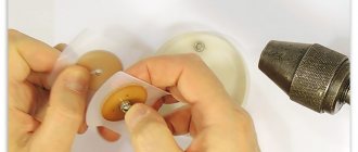
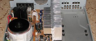
This Printed Circuit Board (PCB) was designed based on the available SP4-1 potentiometers and the selected housing. In this case, the PP is attached not to the ULF housing, but to the current-carrying contacts of the potentiometers, which eliminates the need to use a connecting cable between the regulators and the PP.
The holes marked with arrows pass through the centers of the potentiometer shafts and can be used to mark the corresponding holes in the amplifier housing.
The area of some PCB tracks has been increased to improve the reliability of PCB attachment to the potentiometer legs. The solid fill area has been modified to provide acceptable quality when using a worn printer cartridge. You can read more about this technology here.
And this is a ready-made printed circuit board, manufactured using the technology described here. To connect the PP with other blocks, copper pins are riveted into the corresponding holes in the PP.
Passive tone controls (page 1)
As is known, the rated output voltage of modern audio frequency signal sources (3Ch) does not exceed 0.5 V, while the rated input voltage of most 3Ch power amplifiers (UMZCH) is usually 0.7...1 V. To increase the signal voltage to the level 3Ch pre-amplifiers are used to ensure normal operation of the UMZCH, as well as to match the output impedances of the signal sources with its input impedance. As a rule, it is in this part of the sound reproduction path that volume, timbre and stereo balance are adjusted. The main requirements for preamplifiers are low nonlinear signal distortion (harmonic distortion - no more than a few hundredths of a percent) and a low relative level of noise and interference (no higher than -66...-70 dB), as well as sufficient overload capacity. All these requirements are largely met by the preamplifier of the Muscovite V. Orlov (he took the Japanese AU-X1 amplifier circuit as a basis). The nominal input and output voltages of the amplifier are 0.25 and 1 V, respectively, the harmonic coefficient in the frequency range of 20 Hz at the rated output voltage does not exceed 0.05%, and the signal-to-noise ratio is 66 dB. Input impedance amplifier, tone control limits (at frequencies of 100 and 10000 Hz) from -10 to +6 dB. The device is designed to work with UMZCH, the input impedance of which is at least 5 kOhm. Amplifier (in Fig. 1)shows a schematic diagram of one of its channels) consists of a source follower on transistor VT1, a so-called bridge passive tone control (elements R6-R11.1, C2-C8) and a three-stage symmetrical signal voltage amplifier. The volume control - variable resistor R1.1 - is included at the input of the amplifier, which reduces the likelihood of its overload. The timbre in the region of lower frequencies of the audio range is controlled by a variable resistor R7.1, in the region of higher frequencies by a variable resistor R11.1 (resistors R7.2 and R11.2 are used in another channel of the amplifier). The transfer coefficient of a symmetrical amplifier is determined by the ratio of the resistances of resistors R18, R17 and, with the values indicated in the diagram, is approximately 16. The operating mode of the final stage transistors (VT6, VT7) is determined by the voltage drop created by the collector currents of transistors VT4, VT5 on diodes VD1 connected in the forward direction - VD3. Trimmer resistor R15 serves to balance the amplifier. The amplifier can be powered either from the source that powers the UMZCH, or from any unstabilized rectifier with output voltages of +18...22 and -18...22 V. A possible version of the printed circuit board for one channel of the device is shown in Fig. 2. It is made of foil fiberglass laminate with a thickness of 1.5 mm and is designed for the installation of resistors MLT and SP4-1 (R15), capacitors MBM (C1, C4, C8, C11), BM-2 (SZ, C5-C7) and K50 -6, K50-16 (rest). Capacitors MBM and BM-2 are mounted vertically on the board (one of their terminals is extended to the locally required length using tinned wire with a diameter of 0.5... 0.6 mm). Double variable resistor R1 of any type of group B, resistors R7 and R11 - group B. Transistors KP303D can be replaced with KP303G, KP303E, transistor KP103M with KP103L, transistors KT315V and KT361V-transistors of these series with index G. Field-effect transistors must be selected according to the initial drain current, which at voltage Uс=8 V should not go beyond 5.5...6.5 mA. Diodes D104 are completely replaceable with diodes of the D220, D223, etc. series. Adjustment comes down to setting the trimmer resistor R15 to zero voltage at the output and selecting resistor R18 until an output voltage of 1 V is obtained at an input voltage of 250 mV with a frequency of 1000 Hz (resistor sliders R7, R11 is in the middle, and resistor R1 is in the upper position in the circuit). A significant drawback of the one described, and many other similar devices using transistors, is the relatively large number of elements and, as a consequence of this, the rather large dimensions of the circuit board. Pre-amplifiers based on operational amplifiers (op-amps) are much more compact. An example is a device developed by Muscovite Yu. Solntsev based on the general-purpose op amp K574UD1A (Fig. 3).
His studies showed that the harmonic coefficient of this op-amp strongly depends on the load: it is quite acceptable when its resistance is more than 100 kOhm, it increases to 0.1% when the load resistance decreases to 10 kOhm. To obtain sufficiently low nonlinear distortions, the author added to the specified op-amp a so-called parallel amplifier, characterized by the virtual absence of “step” distortion, even without negative feedback (NFB). With OOS, the harmonic coefficient does not exceed 0.03% in the entire audio frequency range with a load resistance of more than 500 Ohms. The remaining parameters of the preamplifier are as follows: nominal input and output voltage 250 mV, signal to noise ratio at least 80 dB, overload capacity 15 dB. As can be seen from the diagram, the device consists of a linear amplifier with a horizontal frequency response using op-amp DA1 and transistors VT1 - VT4 ("parallel" amplifier) and a passive bridge tone control (elements R12 - R14, R17 - R19, C6 - C9). If necessary, this regulator can be excluded from the path using relay K1 (the signal in this case is removed from the voltage divider R10R11). The amplifier's transmission coefficient is determined by the ratio of the resistance of resistor R3 to the total resistance of resistors R2, R4. The bridge regulator has no special features. At lower frequencies, the timbre is adjusted with a variable resistor R18.1, at higher frequencies with a resistor R13.1. Resistors R12, R14 prevent monotonous rise and fall of the frequency response outside the nominal frequency range of the amplifier. For normal operation of the tone control, the load resistance must be at least 50 kOhm. When working with a signal source whose output voltage contains a constant component, it is necessary to turn on a separating capacitor at the amplifier input (shown in the diagram with dashed lines). All parts of the amplifier, with the exception of the tone control elements, are mounted on a printed circuit board made of foil fiberglass. The board is designed for mounting resistors MLT, SP4-1 (R4), capacitors K53-1a, K53-18 (C1, C4), KM-6b (C2, C3, C5, C6) and MBM (others). Double variable resistors R13 and R18 - any type of group B. The tone control elements are mounted directly on their terminals and connected to the board with shielded wires. Instead of those indicated in the diagram, transistors KT3107I, KT313B, KT361K (VT1, VT4) and KT312V, KT315V (VT2, VT3) can be used in the amplifier. Relay K1 - brand RES60 (passport RS4.569.436) or any other with suitable dimensions and operating current and voltage. Diode VD1 - any with a permissible reverse voltage of at least 50 V. To connect to the amplification path, a detachable connector MRN14-1 is used (its plug is installed on the board). To power the amplifier, a bipolar power supply is required, capable of delivering a current of about 30 mA to the load at a ripple voltage of no more than 10 mV (otherwise, if the installation is unsuccessful, a noticeable background may appear). Adjusting the amplifier comes down to setting the required transmission ratio with and without a connected tone control. In the first case, the desired result is achieved by changing the resistance of the tuning resistor R4 (and, if necessary, by selecting resistor R2), in the second, by selecting resistor R11. The amplifier is designed to work with UMZCH, described in the article by Yu. Solntsev “High-quality power amplifier” (“Radio”, 1984, No. 5, pp. 29-34). The volume control (double variable resistor of group B with a resistance of 100 kOhm) is switched on in this case between its input and the output of the pre-amplifier. The same resistor, but group A, is used as a stereo balance regulator (one of its outer terminals and the output of the slider in each channel is connected to the volume control slider, and the other outermost terminal is connected to the UMZCH input). In recent years, the industry has mastered the production of integrated circuits (ICs KM551UD, KM551UD2), specially designed for operation in the input stages of audio frequency paths of household radio equipment (preamplifiers-correctors of electric players, amplifiers for recording and playback of tape recorders, microphone amplifiers, etc. devices). They are distinguished by a reduced level of self-noise, low harmonic distortion, and good overload capacity. In Fig. 5
The circuit diagram of a pre-amplifier based on the KM551UD2 IC is shown (proposed by Muscovite A. Shadrov). This IC is a dual op-amp with a supply voltage from ±5 to ±16.5 V. An IC with index A differs from a device with index B in half the input common-mode voltage (4 V) and the normalized noise voltage referred to the input (no more than 1 μV with a signal source resistance of 600 Ohms; for KM551UD2B it is not standardized). The rated input and output voltages of this amplifier are the same as those of the device according to the circuit in Fig. 1, harmonic distortion in the frequency range 20..Hz no more than 0.02%, signal/noise ratio (unweighted) 90 dB, volume and timbre control range (at frequencies 60 and 16000 Hz) respectively 60 and ±10 dB, transition attenuation between channels in the frequency range 100..Hz not less than 50 dB. The input and output resistances of the amplifier are 220 and 3 kOhm, respectively. The bridge tone control is included in this case in the OOS circuit, covering the op-amp DA1.1 (hereinafter, the pin numbers of the second op-amp of the microcircuit are indicated in parentheses). At the input there is a fine-compensated volume control on a variable resistor R2.1 with a tap from a conductive element. Loudness compensation (raising low-frequency components at low volume levels) can be turned off using switch SA1.1. Stable operation of the KM551UD2 IC (its frequency response has three bends) is ensured by capacitor C7 and circuit R5C5, the values of which are selected for the transfer coefficient Ki = 10 (the rate of rise of the output voltage with such amplification reaches 3...4 V/μs). Capacitors C12, C13 prevent the amplifier from interconnecting with other devices in the path when powered from a common source. The variable resistor R12.1 (in another channel R12.2) regulates the stereo balance. All parts of the amplifier, except for variable resistors R2, R7, R11 and switch SA1, are mounted on a printed circuit board made of foil fiberglass. It is designed for the installation of MLT resistors, capacitors MBM (C1, C10), BM-2 (SZ-S5, C11), KM (C6, C7, C12, C13) and K50-6, K50-16 (others). Capacitors MBM and BM-2 are mounted vertically. Any dual variable resistors of group A are suitable for regulating volume and stereo balance; resistors of group B are suitable for regulating tone. The amplifier does not require adjustment. The frequency response of bridge tone controls, as is known, has fixed inflection frequencies, therefore, in essence, only the slope of the frequency response sections to the left and right of these frequencies is smoothly adjusted, and its maximum value does not exceed 5...6 dB per octave. To obtain the required limits of tone control at higher and lower frequencies of the audio range, the inflection frequencies must be selected in the mid-frequency region. Such a regulator is ineffective if it is necessary to suppress low- or high-frequency interference in the signal spectrum. For example, with a corner frequency of 2 kHz, the tone control can reduce the level of interference with a frequency of 16 kHz by 15 dB, only at the same time attenuating the spectrum components of 8 and 4 kHz by 10 and 5 dB, respectively. It is clear that in such a case this is not a way out, therefore, to suppress interference at the edges of the spectrum, switchable low-pass (LPF) and high-pass (HPF) filters with a large frequency response slope outside the transparency band are sometimes used to suppress interference. However, even in this case, the desired result is not always achieved, since these filters usually have fixed cutoff frequencies. It's a different matter if the filters are made tunable in frequency. Then, by smoothly shifting the boundaries of the range of transmitted frequencies in the desired direction, it will be possible to “remove” the interference beyond its limits without affecting the shape of the frequency response within the range. By the way, it is advisable to make such filters non-switchable: they will help combat infra-low-frequency interference from the mechanism of an insufficiently advanced electric player.
STEREO PRE-AMPLIFIER
E. Devyatov
Recently, radio amateurs have been paying increasing attention to high-quality audio power amplifiers. However, the quality of the sound reproduction path is greatly influenced by the pre-amplifier, which must have a low harmonic distortion, low self-noise, high overload capacity, as well as good matching with various audio frequency signal sources. The proposed stereo preamplifier largely meets these requirements. It is designed to work together with any power amplifier with a sensitivity of 0.5...1 V and an input impedance of at least 1 kOhm. A special feature of the amplifier is the absence of clicks when turning all control buttons on and off.
The input signal goes to the variable resistor R1, which is a balance regulator, and from its slider to the gate of the field-effect transistor VT1, which is connected by the source follower. The source follower ensures the high input impedance of the amplifier and the normal operation of the thin-compensated volume control. From the source of transistor VT1, the signal goes to variable resistor R6, which serves as a volume control, and its slider goes to the input of a voltage amplifier made on transistors VT2 and VT3 of different structures. The gain of this stage is 22 dB. From the collector of transistor VT3, the signal is supplied to the tone controls, and then to another voltage amplifier on transistors VT4 and VT5, which compensates for the weakening of the signal at the sound tone control unit. The timbre of the sound at lower frequencies is regulated by variable resistor R22, at higher frequencies - with resistor R27. The SB1 button turns on the loudness compensation performed on the resistor R6 without a tap. Use the SB2 button to switch the amplifier channel to the “Mono” mode. The SB3 button turns on the low-pass filter with a cutoff frequency of 10 kHz, and the SB5 button turns on the low-pass filter with a cutoff frequency of 60 Hz. The slope of the frequency response of the filters is 6 dB/octave. The SB4 button turns off the tone controls to obtain a linear frequency response. Both preamplifier channels are powered by a stabilized 20 V DC source. Maximum current consumption is 50 mA. Construction and details. The amplifier is assembled on a printed circuit board measuring 135x50 mm (Fig. 2) from single-sided foil fiberglass laminate with a thickness of 1.5 mm. All fixed resistors are MLT-0.25, variable resistors are dual SPZ-ZOg. Resistors R6, R22 and R27 must be group B, and R1 - group A. Trimmer resistor R34-SP-5. Capacitors - K50-6 and KM. Push-button switches P2K. The KP303G transistor can be replaced with any of the same series. Instead of KT3102D, you can use transistors of the same series with letter indices A, B, V, KT315 (B, D) or KT342 (A, B), instead of transistors KT3107D-KD3107 (B, D, E, F), KT361 (B, D) or KT502(B, G).
Setting up an amplifier begins with checking that there are no errors in the installation. Then turn on the power and select resistor R3 to set the voltage at the source of transistor VT1 to 8...9 V. Next, a signal with a frequency of 1000 Hz and a voltage of 250 mV is supplied to the input from the generator, and an oscilloscope and a high-resistance voltmeter are connected to the output. The volume and tone control sliders are set to the top position according to the diagram, and the balance control to the middle position. Using trimmer resistor R34, the voltage at the amplifier output is set to 1 V and the generator voltage is increased until two-way signal clipping occurs. Symmetrical limitation of the signal at the output of the amplifier is achieved by selecting resistor R12. If necessary, resistor R29 can be selected more accurately. The harmonic distortion coefficient, indicated in the main technical characteristics of the described preamplifier, was measured by an automatic nonlinear distortion meter S6-7, and the GZ-112-1 generator was used as an input signal source.
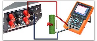
Testing the tone block.
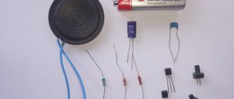
The picture shows a diagram for switching on a block of regulators when taking Amplitude-Frequency Characteristics (AFC).
I used the SpectraLAB program to measure the frequency response, both as a Sweeping Frequency Generator (SWG) and as a spectrum analyzer.
True, I had to run two copies of the program at once. The GKCH is on one computer, and the analyzer is on another.
When running the generator and analyzer on the same computer, due to the low attenuation between the inputs and outputs of my built-in audio card, the measurement error was unacceptable.
On the graph of the frequency response of the regulator block with loudness compensation turned on and the middle position of the HF and LF regulators.
The frequency response of the tone block, taken at the maximum rise (upper curve) and maximum fall (lower curve) of high frequencies and low frequencies.