Circuit of a high frequency generator that produces signals in the range from 10 to 50 MHz. The signal can be frequency modulated by applying low-frequency voltage from an LFO or microphone. The frequency deviation depends on the magnitude of this AF voltage. If you need a deviation of 50-100 kHz, then, at the extremely high .
Schematic diagram of a homemade logic pulse generator with a frequency from 1 Hz to 10 KHz, assembled on a 4011 chip (K561LA7). When repairing and setting up circuits on digital microcircuits, a logic pulse generator can be very useful. In general, it is a square wave generator.
A low-frequency sine wave generator is a very important device in the laboratory of any radio amateur. Perhaps everyone already has one. But I still want to introduce the magazine’s readers to my generator. The generator is designed as an independent device, powered from the mains. But the scale.
A simple homemade generator-probe, with adjustable output frequency from 100 Hz to 10000 Hz, is made on the K561LA7 microcircuit. If you need to impromptu check the passage of a signal along the audio path, many luminaries use their own finger as a low-frequency generator (50 Hz network interference), adjusting.
Schematic diagram of a homemade wide-range sinusoidal signal generator for laboratory purposes, made on the MAX038 microcircuit. A sine wave generator is one of the most important instruments in a radio amateur laboratory. Usually two generators are made, low-frequency and high-frequency.
Schematic diagram of a simple smooth range generator on the HC4046 chip, Frequency up to 50 MHz. The NS4046 chip (as well as analogs MM74HC4046N, MJM74HC4046 and others) is an RC oscillator with a PLL capable of generating a stable frequency of up to 50 MHz, which allows you to make a GPA.
A schematic diagram of a low-frequency signal generator, which is made on the KR140UD708 op amp, is presented. A low-frequency generator is one of the most necessary devices in an amateur radio laboratory. With its help, you can set up various amplifiers, measure the frequency response, and conduct experiments.
To power electronic watches, and possibly other equipment made in the USA and some other countries, you need a voltage with a stable frequency of 60 Hz. If you have a quartz resonator with a frequency of 1966 08 kHz, it is not difficult to obtain (see, for example, the article by V. Polyakov “Converter.
The proposed generator design can be used to configure cascades of radio receivers and various analog and digital devices. The generator generates low-frequency (LF) and high-frequency (HF) sinusoidal and square waves. HF oscillation range 0.15. 1.6 MHz with smooth .
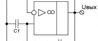
The former contains an RC trigger assembled on 2I-NOT logic elements, an integrating circuit R1, R2, C1 and an inverter on transistor V1. If the logic level is high at the input of the shaper, a high logic level will appear at output 1, and a low logic level at output 2. Upon arrival at the entrance.
Circuit of a high frequency generator that produces signals in the range from 10 to 50 MHz. The signal can be frequency modulated by applying low-frequency voltage from an LFO or microphone. The frequency deviation depends on the magnitude of this AF voltage. If you need a deviation of 50-100 kHz, then, at the extremely high .
Schematic diagram of a homemade logic pulse generator with a frequency from 1 Hz to 10 KHz, assembled on a 4011 chip (K561LA7). When repairing and setting up circuits on digital microcircuits, a logic pulse generator can be very useful. In general, it is a square wave generator.
A low-frequency sine wave generator is a very important device in the laboratory of any radio amateur. Perhaps everyone already has one. But I still want to introduce the magazine’s readers to my generator. The generator is designed as an independent device, powered from the mains. But the scale.
A simple homemade generator-probe, with adjustable output frequency from 100 Hz to 10000 Hz, is made on the K561LA7 microcircuit. If you need to impromptu check the passage of a signal along the audio path, many luminaries use their own finger as a low-frequency generator (50 Hz network interference), adjusting.
Schematic diagram of a homemade wide-range sinusoidal signal generator for laboratory purposes, made on the MAX038 microcircuit. A sine wave generator is one of the most important instruments in a radio amateur laboratory. Usually two generators are made, low-frequency and high-frequency.
Schematic diagram of a simple smooth range generator on the HC4046 chip, Frequency up to 50 MHz. The NS4046 chip (as well as analogs MM74HC4046N, MJM74HC4046 and others) is an RC oscillator with a PLL capable of generating a stable frequency of up to 50 MHz, which allows you to make a GPA.
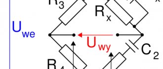
Bridge of Wine
The Wien bridge itself is a bandpass filter consisting of two RC filters. It emphasizes the central frequency and suppresses other frequencies.
The bridge was invented by Max Wien back in 1891. On a schematic diagram, the Wien bridge itself is usually depicted as follows:
Picture borrowed from Wikipedia
The Wien bridge has a ratio of output voltage to input voltage b=1/3 . This is an important point, because this coefficient determines the conditions for stable generation. But more on that later
How to calculate frequency
Autogenerators and inductance meters are often built on the Wien Bridge. In order not to complicate your life, you usually use R1=R2=R and C1=C2=C . Thanks to this, the formula can be simplified. The fundamental frequency of the bridge is calculated from the ratio:
Almost any filter can be thought of as a frequency-dependent voltage divider. Therefore, when choosing the values of the resistor and capacitor, it is desirable that at the resonant frequency the complex resistance of the capacitor (Z) is equal to, or at least of the same order of magnitude as, the resistance of the resistor.
Zc=1/ωC=1/2πνC
where ω (omega) is the cyclic frequency, ν (nu) is the linear frequency, ω=2πν
Wien bridge and operational amplifier
The Wien bridge itself is not a signal generator. For generation to occur, it must be placed in the positive feedback circuit of the operational amplifier. Such a self-oscillator can also be built using a transistor. But using an op-amp will clearly simplify life and give better performance.
Re: Amplifier for DDS Signal Generator.
———- Message added 11.43 ———- Previous message was 11.40 ———-
I also have a DDS generator with a 14-bit DAC, but I don’t need 100 watts, I wanted to attach some kind of ear composite, but I don’t have time
———- Message added 12.02 ———- Previous message was 11.43 ———-
I keep looking at Hantek, in theory, if the DAC is really 16 bit, then if you give it a normal exhaust, you can get a very good device.
———- Message added 02/12 ———- Previous message was 02/12 ———-
Gain factor of three
The Wien bridge has a transmittance b=1/3 . Therefore, the condition for generation is that the op-amp must provide a gain of three. In this case, the product of the transmission coefficients of the Wien bridge and the gain of the op-amp will give 1. And stable generation of the given frequency will occur.
If the world were ideal, then by setting the required gain with resistors in the negative feedback circuit, we would get a ready-made generator.
This is a non-inverting amplifier and its gain is determined by the ratio: K=1+R2/R1
But alas, the world is not ideal. ... In practice, it turns out that to start generation it is necessary that at the very initial moment the coefficient. the gain was slightly more than 3, and then for stable generation it was maintained at 3.
If the gain is less than 3, the generator will stall; if it is more, then the signal, upon reaching the supply voltage, will begin to distort and saturation will occur.
When saturated, the output will maintain a voltage close to one of the supply voltages. And random chaotic switching between supply voltages will occur.
Therefore, when building a generator on a Wien bridge, they resort to using a nonlinear element in the negative feedback circuit that regulates the gain. In this case, the generator will balance itself and maintain generation at the same level.
Schematic diagram
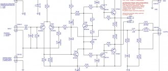
The maximum output level (position 1/1 S2) of sinusoidal voltage (RMS) is 3.1 V. Accordingly, in other positions of S2 the maximum output signal (RMS) is 310mV and 31mV. The generator is powered from the mains through a built-in power supply on a low-power power transformer.
The generator circuit is a ULF with a push-pull output stage, covered by positive feedback by an RC Wynne bridge circuit. The frequency is determined by variable resistors R2 1 and R2.2, which are components of a dual variable resistor used as an organ for smoothly adjusting the frequency within the selected range. And capacitors switched by a double switch S1.1-S1.2.
Rice. 1. Schematic diagram of a laboratory low-frequency signal generator 15 Hz - 160 KHz.
During installation, variable resistors must be soldered so that when the handle is rotated, their resistances change equally (if turned on incorrectly, when the handle is rotated, the resistance of one variable resistor will decrease while the resistance of the other will increase).
The closer the adjustment characteristics of the resistors that make up the block of variable resistors, the less signal distortion will be at the output. The same applies to the capacitors that form the Winn bridge - their capacitances simultaneously operating in the same range should be as identical as possible (C1=C5, C2=C6, C3=C7, C4=C8, as the inequality of these capacitances increases, distortion increases).
The nonlinear distortion coefficient is no more than 0.3% over the entire frequency range (subject to careful tuning of the generator and small spacing of the capacitors and resistors of the Winn bridge arms).
If there is only a Winn bridge, the amplifier (generator) circuit will enter the signal limiting mode. That is, in this case, this is an overload that will cut off the vertices of the sinusoids and the signal will be more similar to a rectangular one than a sinusoidal one.
Therefore, a negative feedback system is also necessary, which will reduce the transmission coefficient of the amplifier so that the swing of the output signal does not go into the zones of limitation and nonlinearity.
In addition, there must be automatic adjustment of the OOS depth, keeping the transmission coefficient at the optimal value, which here is formed by resistors R7, R6, R5, as well as capacitor C9. The element that regulates the depth of environmental protection is the H1 incandescent lamp.
As is known, the resistance of an incandescent lamp strongly depends on the current through it, since the current causes heating of the filament made of a high-resistance metal alloy. The greater the current, the greater the heating and the greater the resistance of the light bulb. Here the lamp is connected to the OOS circuit; as the resistance in this circuit increases, the depth of the OOS increases and the transmission coefficient of the amplifier decreases.
The output alternating current flows through the lamp, so the heating of the lamp depends on its value. In this way, the output signal level is stabilized within the linear portion of the characteristics of the low-frequency amplifier.
The amplifier that forms the basis of the LFO is built on transistors in a three-stage circuit with a bridge output stage and direct connections between the stages.
To eliminate the “step,” the bias voltage on the bases VT3 and VT4 differs by the amount specified by a chain of three diodes VD1-VD3. Smooth adjustment of the output signal is carried out by variable resistor R11, stepwise by switch S2, switching divider resistors R12-R14.
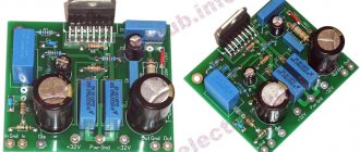
The power supply produces a bipolar DC voltage of approximately + 11V. The power supply uses a low-power power transformer T1 with one secondary winding for a voltage of 9V. In order to obtain bipolar voltage from such a transformer, two half-wave rectifiers on diodes VD4 and VD5 are used.
As a result, the positive half-wave of AC is used to generate a positive DC voltage, and the negative half-wave of AC is used to generate a negative DC voltage.
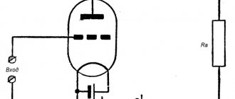
Amplitude stabilization on an incandescent lamp
In the most classic version of the generator on the Wien bridge at the op-amp, a miniature low-voltage incandescent lamp is used, which is installed instead of a resistor.
When such a generator is turned on, at the first moment, the lamp spiral is cold and its resistance is low. This helps to start the generator (K>3). Then, as it heats up, the resistance of the spiral increases and the gain decreases until it reaches equilibrium (K=3).
Amplitude stabilization on LEDs
VD1 and VD2 in the negative feedback circuit .
The main gain is set by resistors R3 and R4 . The remaining elements ( R5 , R6 and LEDs) regulate the gain in a small range, maintaining the generation stable. Resistor R5 can be used to regulate the output voltage in the range of approximately 5-10 volts.
It is advisable to use low-resistance resistors ( R5 and R6 ) in the additional OS circuit. This will allow significant current (up to 5mA) to pass through the LEDs and they will be in optimal mode. They will even glow a little