Horn. Design and calculation
As you know, a loudspeaker can be horn-loaded. There are two known modifications of the horn head device. In the first of them, the so-called wide-neck, the throat of the horn is directly adjacent to the diffuser of the head. Due to the fact that the mouth has a diameter larger than the diameter of the head diffuser, the directionality of such a horn is sharper than the directionality of the head. Therefore, sound energy is concentrated on the horn axis and the sound pressure increases here.
In the second modification (narrow-neck), the horn is connected to the diaphragm (diffuser) of the head through a pre-horn chamber, which plays a role similar to that of an electrical matching transformer. Here the mechanical resistance of the moving system of the head and the throat of the horn is consistent, which increases the load on the diaphragm and, as it were, increases its radiation resistance, due to which the efficiency greatly increases. Thus, this makes it possible to obtain high sound pressure.
There are many different types of horns, but practically the most often used in household equipment is an exponential horn, the cross section of which varies according to the law:
S
= S 0 ∙ eβx
,
where S 0
– area of the horn inlet,
β
– exponent index.
In Fig. 1 shows various horn profiles:
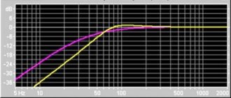
As can be deduced from the formula above, the cross-section of such a horn increases by the same percentage for each unit of its axial length. The value of this percentage increment determines the lower limit frequency of the horn. In Fig. Figure 2 shows the dependence of the percentage increment of the cross section per 1 cm of axial length on the lower limit frequency. So, for example, to ensure that the horn reproduces the lower limit frequency of 60 Hz, the cross-sectional area must increase by 2% for every 1 cm of its axial length. This dependence can also be represented in the form of the following expression:
f gr.n
= 6.25 ∙ 103 ∙ log (0.01 k + 1)
where k
– increment of cross-sectional area, %.
For low frequencies (up to 500 Hz), this expression is simplified and takes the form: f gr.n
= 27k
If the horn is made of a square or circular cross-section, then the side of the square or the diameter of the circle should increase for every 1 cm of the length of the horn by √ k
percent.
If it is made of a rectangular cross-section with a constant height, then the width of the horn section should increase by k
percent for every 1 cm of its length.
However, maintaining the required percentage increase in the cross-section is not yet sufficient for good reproduction of low frequencies. It is necessary to have a sufficient area of its outlet - the mouth. Its diameter (or the diameter of an equal circle) should be:
D
≥ λ gr.n / ∏ ≈ 110 / fgr.n
So, for the lower boundary frequency of 60 Hz, the diameter of the mouth will be about 1.8 m. For lower boundary frequencies, the size of the mouth will be even larger. In addition, the horn head, well reproducing low frequencies (above f gr.n
), does not reproduce a wide frequency range well enough.
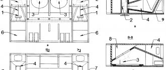
Given this, it is advisable to have two horn heads: one for reproducing low frequencies and the other for high frequencies. In Fig. Figure 3 shows the appearance and cross-section of such a speaker with two horn heads and a bass reflex for reproducing frequencies below the f gr.n
of the horn.
The use of low-frequency horn designs in residential premises is limited by the size of the room. However, if such a possibility exists, then the calculation of the horn should begin by specifying the area of the mouth at the selected lower limit frequency, reducing the cross-section by percent for every 1 cm of axial length until a cross-sectional area equal to the area of the head diffuser is reached. At the same time, in order to mate the head with a wide-necked horn, the horn must have a cross-section of the same shape, i.e. round or elliptical. For narrow-neck horns, the identity of the cross-sectional shape and the diaphragm of the head is not necessary, since the throat and diaphragm are articulated through the pre-horn chamber. Note that the height of the chamber must be significantly greater than the amplitude of oscillations of the moving system of the head in order to avoid the occurrence of strong nonlinear distortions due to the asymmetry of the deformation of the air volume in the chamber. However, if the pre-horn height is too high, high-frequency reproduction is impaired.
Sometimes, in order to reduce the overall dimensions of speakers, rolled horns are used, the various designs of which are shown in Fig. 4. Rolled horns are calculated in almost the same way as regular ones. When calculating the profile, it is necessary to ensure that at the transition points (knee bends) there are no sudden changes in sections that cause irregularities in the frequency response.
ACTIVE SPEAKER SYSTEM
WITH INCREASED OUTPUT AT LOW FREQUENCIES
The birth of this description was preceded by a whole series of calculations, the production of prototypes, some successful and some not so successful. In the end, these were the dimensions of the universal housing of an active acoustic system of an economy class, suitable for MOST acoustic heads. When building this acoustic system, the goal was not to achieve the HIGH-END class; it should be an acoustic system competitive with the average price category of stage equipment, reliable and maintainable even in “field” conditions. When creating this acoustic system, four goals were set: Not to sacrifice much sound quality Not to spend a lot of money on construction To get increased output at low frequencies, since the loudspeaker system was intended for large rooms and open spaces Not to “sharpen” the body for a specific set of dynamic drivers These goals were We have solved and here is a description of how to make an acoustic system yourself, without using any scarce and expensive components.
Several options were tested - closed enclosures, enclosures with bass reflexes, bandpasses and horn enclosures. I liked the latter the most, but the CORRECT horn housing is quite labor-intensive to calculate and manufacture. Therefore, we decided to compile some kind of arithmetic average similarity to the horn, since for almost all types of speakers included in the calculations, one trend was clearly visible - the length of the horn is about 3 meters and the horn should have a more or less constant expansion plus a bell at the end. The horn can be folded in different ways, for example, take the Hitchcock horn system and the length of the horn itself depends on the desired resonant frequency. The length of the horn can be calculated using the formula L = 344 / F, where 344 is the speed of sound, F is the resonance frequency. Since the dynamic head is facing the listener, it is necessary to receive a signal at the output of the horn in antiphase, because the exciter of air vibrations for the horn will be the back side of the diffuser. Therefore, the resulting horn length is divided in half, i.e. The radiation of sound waves turns out to be shifted in phase relative to the front side of the diffuser by exactly 180 degrees. In essence, this is how the SOUND BARREL turned out. In other words, this is a fairly universal case for almost ANY low-frequency section and the output power depends only on the power amplifier and speakers used. The most accessible and not very expensive are acoustic systems designed for cars, the so-called car acoustics. Based on this, the choice was made on this acoustics. A 400 W (normal W) subwoofer speaker and a set of two 13 cm two-way dynamic heads for reproducing the mid-high frequency range were taken. It’s worth making a reservation right away - 2 x 40 W initially chosen for mid-high frequencies turned out to be not enough and when supplied to the assembled kit 500 W (slight overload for texting reliability). Both speakers died for a long time. Therefore, for the mid-high frequency range it is necessary to take a kit with a power of at least 60 W, and there are no round dimanic heads of such power less than 16 cm. Therefore, the final set of dynamic heads for a power of 400 W looked like this: a low-frequency head - a subwoofer for open speaker systems with a diameter of 31 cm with a maximum long-term power of 400 W and a set of two 16 cm two-way dynamic heads for midrange-HF with a maximum short-term power of 100 W. However, it should be noted here that this design of the speaker system is quite suitable for lower powers, which is what actually caused the appearance of fully ready-to-install modules for 150 W, 300 W and its m
modified version, 550 W and stereo version, 150 W each channel.
The modules contain the entire set of necessary devices - a switching power supply, AC protection from DC voltage, some are also equipped with output power indicators and overheating protection, as well as systems for smoothly increasing the volume at the moment of switching on. The main difference for speaker systems of different powers lies in the materials used - for powers up to 150-180 W, 18 mm thick chipboard is used, for powers up to 300 W - 22 mm thick chipboard or 18 mm thick plywood, for powers up to 600 W, 22 mm thick plywood . The blanks are cut in such a way that the thickness of the material is taken into account only when making the back wall, while the other dimensions do not change. When choosing a material, it is necessary to make allowance for the fact that depending on the year of manufacture, the quality of chipboard differs markedly, therefore, for powers above 150 W, we strongly recommend that you go to relatives and friends and inquire about the availability of old wardrobes, bookcases and sideboards. Chipboard produced before 1990 has a much higher density and is more difficult to process, since the adhesive components used at that time were much stronger and the sawdust material was compressed much more strongly. If you're lucky, you may stumble upon a very old wardrobe with a chipboard thickness of 22
mm. This can be considered a gift of fate, since even 800 W speakers were made from such material only by installing a spacer cross inside the woofer box. You can advertise in the local newspaper about buying old furniture; in any case, it will be much cheaper than buying new, rather loose chipboard and much cheaper than buying plywood.
Appearance of a speaker system with increased efficiency at low frequencies. Right without rear wall
You should start by making a block of mid-high frequency heads. To do this, you will need to cut out 4 parts, the dimensions of which are shown in Figure 1. After this, a U-shaped structure is assembled from parts 2-4 using 3.5x45 self-tapping screws. Before screwing in, you need to drill a hole under each screw with a drill with a diameter of 3 mm. The drill needs to be elongated, i.e. so that the resulting hole is longer than the screw. Pre-drilling holes for screws completely eliminates delamination of the material during screwing in the screws, and the slightly smaller diameter of the holes in no way reduces the mechanical strength of the connection. Before screwing in the screws, the contact points between the chipboard and each other must be coated with polyurethane foam.
Perhaps it’s worth saying a few words separately about foam. Polyurethane foam is primarily good because it has very good adhesive properties. In addition, expanding in all directions, it completely fills all existing voids and cracks. It is also quite simple to obtain different densities of foam in a frozen state - the slower it comes out of the container, the less it will increase in size and will have a much higher density. And the opposite effect - the more you press the release valve, the faster it will come out of the balloon, and accordingly, it will swell more and increase in size. In addition, hardened foam has good mechanical properties and is a good sound-absorbing material. For greater clarity, we introduce three concepts of density - DENSE
, when the foam is released from the balloon at the minimum possible speed and more closely resembles sour cream or cream for a cake and increases in size barely noticeably,
MEDIUM
- when the foam is released from the balloon at an average speed, it immediately begins to increase,
LOAF
- when the foam from the balloon is released at the maximum speed , there is immediately a lot of it and it begins to increase in size.
But let's get back to assembling the MF-HF box. Parts 2 and 3 are attached with their ends to part 4 with four 3.5x45 self-tapping screws, the contact points of the parts are coated with dense foam, then part 1 is attached to the resulting structure in such a way that the upper part of part 1 coincides in height with the upper part of part 2. Contact points They are also coated with dense foam.
Figure 1 Patterns for making the mid-high frequency side of an active speaker system.
After this, after allowing the foam to harden and cutting off the protruding foam from the outer seams, holes are cut out in part 1 for dynamic heads and forced cooling fans. The forced cooling system was chosen based on economic considerations - even a pair of fans are much cheaper than increasing the heat sink area to the required size, especially since the amplifier's output power exceeds 100 W. For clarity, let's say that one radiator from an old amplifier with a power of 50 W (Lort), installed on a sheet of aluminum 5 mm thick and measuring 300x150 mm, is quite enough for the SOUND BARREL 150 amplifier in the presence of two computer fans with a diameter of 80 mm and a consumption of 0.12 A ( current is indicated on the fan and determines the performance of the fan). The diameter of the holes for fans is 80 mm, by the way, sometimes you can find on sale fans with a diameter of 90 mm and a consumption of 0.24 A, these are ideal for the SOUND BARREL 550 amplifier. There are also fans with a diameter of 80 mm with a current consumption of more than 0.12 A These fans are best used for SOUND BARREL 300, SOUND BARREL 300M and SOUND BARREL 2x150 amplifiers. It is better to cut the holes for the dynamic heads according to the existing templates, which are ALWAYS drawn on the packaging boxes of car speaker systems. The result is the design shown in Figure 2.
Figure 2 External view of the mid-high frequency box for an active speaker system.
A few words about making round holes. There are quite a few methods, but the most preferred is still a jigsaw. Stepping back from the edge of the marking circle approximately 10 mm, drill a hole with a diameter for a jigsaw file and begin sawing in a spiral, bringing the file to the marking. It should be noted that there are special saw blades for jigsaws for cutting round holes. You can even distinguish them by their appearance - saws for cutting round workpieces have additional small teeth on the back side, which, when cutting the material, do not allow the file to break. When cutting out a round part with a regular file, the resulting hole has a cone-shaped shape, since the file bends when turning. After cutting the holes, the box must be wiped with a damp cloth and all sawdust must be carefully removed, since when marking the installation and mounting holes of the dynamic heads, sawdust may get into the speaker's acoustic system, which is highly undesirable. After marking ALL the required holes for mounting the speakers and mounting the amplifier with the radiator, the dynamic heads should be packed again in cellophane and a shipping box, and only after that the required holes should be drilled. Now you need to cut out 4 parts, the dimensions of which are shown in Figures 3 and 4. They will serve to create the inside of the horn.
Figure 3 Upper, lower and technological blanks for the inner part of the horn.
Figure 4 Load-bearing wall and inner horn assembly
After assembling and obtaining the workpiece shown in Figure 4 on the right (it is assembled in the same way as the box of MF-HF heads - using a 3.5x55 screw and dense foam in the places where the chipboard contacts each other), it is not worth filling the area shown in the figure with foam, until it is - a little bit later. Part 8 is installed approximately in the middle. Next, four blanks are made, shown in Figure 5. In essence, they will serve as the sidewalls, top and bottom parts of the body of the active acoustic system.
Figure 5 Sidewalls, top and bottom of the acoustic system
Then the inner part of the horn is installed between the sidewalls. The main condition for installation is that part 5 must be located from the edge of the sidewall exactly to the width of parts 13 and 14, in this case it is 100 mm. Suorka is made with self-tapping screws. Do not forget to drill holes, and for greater rigidity in the material through which the self-tapping screw passes through, it is better to drill a hole with a diameter of 4.2 mm, but where the self-tapping screw will be screwed only with a drill with a diameter of 3 mm. In Figure 6 on the right, ALL holes in part 9 are 4.2 mm in diameter, and in the ends of the workpieces 11, 12, 6, 5, 7, 16 ALL holes are 3 mm in diameter. We coat the contact areas of the chipboard with dense foam. After fixing the inner part of the horn to the sides of the active acoustic system, installing the upper part 11 and the lower part 12, installing additional pads 16 and 17, we begin to assemble the horn itself. To do this, you will need parts 13 and 14 (Figure 6), as well as the back wall (Figure 7). After assembling the inner part of the horn and the sidewalls, installing part 15, the corner between part 5 and part 6 is filled with foam, and starting from the connection point of parts 5 and 6, the foam is dense, then the middle and top layer is made of loose foam. Thus, the heterogeneity of the foam completely eliminates the resonant effects of the “visor” 6 and more tightly connects it to part 5. Before installing part 11 (top cover), the resulting container between parts 9, 15, 5 ( fill the figure halfway with loose foam and only after that install part 11. As its volume increases, the foam will either completely or almost completely fill this box.The box created between parts 7, 5 and 12 is filled in the same way - dense foam is poured from the corner, the second layer is the middle and the top layer is as loose as possible. The resulting bulges and irregularities should not be cut off; they are quite smooth and will not produce whistling sounds, but the irregularities completely eliminate the possibility of standing waves occurring.
Figure 6 Horn baffles (13, 14) and additional pads (16,17), upper bell (17) and installation of the inner part of the horn to the sidewalls.
Figure 7 Rear wall of the acoustic system.
Next, parts 13 and 14 are installed with fastenings, but before this it is necessary to round the end of the upper part of part 13 and the lower part 14 (in the figure they are angular, but should be round. This for a horn, although not very important, is better to do anyway. This can be done with a special grinding wheel for a grinder - many strips of sandpaper are glued to the wheel, and there is both coarse and fine sandpaper. It is better to use coarse sandpaper - at high speeds, without pressing hard, you can get a fairly smooth rounded surface. Parts 13 and 14 are attached to part 5 using 3.5x55 screws.Next, the back cover (Fig. 7) is wrapped with cellophane so that the cellophane is on the inside of the lid and the cover is attached to the body using 3.5x55 screws, but not completely , but only the upper and lower parts of the body. As soon as all the holes are drilled, the cover is removed and the corners of the horn are filled with dense foam with the first layer, then with middle foam. First, it is better to fill the lower part, the corners between the parts are 13-12-10, attach the back cover and let the foam harden, then turn the speaker body over, remove the back cover and fill the corners between parts 9-11-14 and close the back cover again. After the foam has hardened, the back cover is removed again and the kissing material is removed from it, which protected the cover from sticking to the foam poured into the corners of the horn. The hardened foam is given an approximate quarter-circle shape using a stationery cutter, i.e. trim off the excess foam until you get the look in Figure 8. Next, you should drill holes in the rear wall for installing the linear input connector and the 220 network connection connector and the linear input wire connector and the network wire. Figure 9 shows an example of fastening a linear input wire, which should have a shielding braid and the tighter the better.
Figure 8 Manufacturing of horn baffles and roundings.
After this, you should secure the back wall, coating the ends of the body parts in contact with it with dense foam. And now the rear wall is secured completely - along the perimeter and to the horn partitions (Figure 9, left). Next, a sheet measuring 410x430 mm is cut out of either denser chipboard or plywood lid, which will serve to fasten the low-frequency dynamic head of the speaker system. In the middle, a circle is cut out with a jigsaw according to the template available on the packaging box of the dynamic head and the installation holes for the screws are drilled. After this, the column is finally assembled and all irregularities and parts that do not fit together are smoothed out with a circle of sandpaper installed in a grinder. You should also drill holes in the sides of the housing for attaching the mid-HF box. After this, the box under the midrange-HF head and the sheet under the woofer head are removed and the body is covered with acoustic fabric, and the inside of the horn is also covered with fabric; special attention should be paid to pasting the sidewalls from the inside, since it is this material that will serve as an insulator of sound vibrations inside the box. After pasting and drying the acoustic fabric, a power amplifier unit with a power supply is installed on the back wall of the MF-HF box; inside the box, a separating capacitor of about 50 μF can be attached in any way, preferably an MBM, but they are now quite rare, so you can connect 10 pieces in parallel capacitors of 4.7 μF, or 5 pieces of 10 μF each. The voltage must be at least 100 V. At the bottom of the LF box, a separating inductance is attached in any way, wound on a mandrel with a diameter of 20 mm and containing layers of 20 turns of wire with a diameter of 1 mm for a power of 150 W, 1.5 mm for a power of up to 300 W and 2 mm for power up to 600 W. It is better to use the wire in mica or fiberglass insulation. After winding, the coil must be “painted” with epoxy glue.
Figure 9 Final assembly of the active speaker system housing.
Next, the circuit diagram shown in Figure 10 is assembled. The “ROOM-STREET” mode switch, the output power indicator, if available, and the power switch are installed on any sheet material - fiberglass, plywood, fiberboard sheet, plastic. It is only necessary to firmly fix this panel to the box of mid-high frequency heads so that when this box is dismantled, these controls and indications remain connected to the amplifier block and do not block more than half of the resulting window between the horn bell and the box of mid-high frequency speakers, since this will impede air circulation and will cause the power amplifier heatsink to overheat.
Figure 10 Schematic diagram of an active acoustic system and approximate appearance.
Well, that’s all - you yourself have assembled the body of a horn-powered active acoustic system, the power of which depends only on the material used and the installed power amplifier.
ALL DRAWINGS IN SPL FORMAT ARE POSSIBLE. OPEN WITH SPLAN 6, WHICH CAN . WHEN PRINTING DRAWINGS FROM THIS PROGRAM, YOU OBTAIN DRAWINGS IN A SCALE OF 1:10. So you can measure with a ruler and transfer it to the material, in case of any confusion with the dimensions. NOTE. When installing fans directly on radiators, they should not be installed parallel to the radiator, but using washers, stands, etc. tilt them slightly in the vertical plane, by 10...15°, so that the air flow passes through the radiator fins and goes upward. In this way, air circulation will occur inside the system and air heating will be eliminated (Fig. 11).
Figure 11 - fan orientation relative to the power amplifier radiator.
It is better to make the lower holes of part 1, intended for installing fans, not round, but to make one rectangular one with a height of 80 mm and a width of 200...250 mm.
If nothing is clear, then look
Site administration address
DON'T FIND WHAT YOU WERE LOOKING FOR? GOOGLE:
CUSTOM SEARCH STRING