The bipolar power supply proposed by V. Oreshkin largely meets the mutually exclusive requirements for the UMZCH supply voltage stabilizer [1, 2]. This note describes a modified circuit that allows, by simple means, to increase the stabilization coefficient and reduce the output resistance while maintaining a small time constant of the aperiodic process. The modification came down to replacing ballast resistors in compensation stabilizers with current sources and taking into account the recommendations of Texas Instruments for constructing power supplies for UMZCH.
↑ Schematic diagram of the upgraded UMZCH power supply
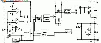
The diagram of a bipolar power supply is shown in Fig. 1.
Fig.1. Bipolar power supply UMZCH
It consists of two galvanically unconnected rectifiers VD1, C1, C2, C5, C6, C9, C11, C13 and VD2, C3, C4, C7, C8, C10, C12, C14, two parametric stabilizers made on zener diodes VD3, VD4 and current sources on transistors VT5, VT6, and emitter followers on transistors VT1, VT3 and VT2, VT4. The stabilization coefficient is increased due to the supply of the reference voltage source of one stabilizer from the output voltage of the other and the use of current sources instead of resistors.
The rectifiers are assembled on diode bridges VD1, VD2, consisting of double Schottky diodes with a common cathode 16CTQ100. The diodes are connected in parallel.
Capacitors C1...C8; C9, C10 and RC - chains R9, C23 and R10, C24 are installed in accordance with the recommendations of Texas Instruments for the construction of power supplies for UMZCH [3].
To reduce noise, each zener diode VD3, VD4 is shunted by a pair of capacitors - oxide and film (C15, C17 and C16, C18, respectively).
Current sources on transistors VT5, VT6 contain parametric stabilizers HL1, C19, C21, R8 and HL2, C20, C22 in the bases of the transistors.
The current of each source is equal to: IVD4=(UHL1-UbeVT5)/R4=(1.76-0.56)/0.13=9.2 mA, IVD3=(UHL2-UbeVT6)/R7=9.2 mA.
Resistors R5, R6 reduce the power dissipated on the collectors of the current source transistors.
The collectors (cases) of powerful transistors VT1, VT2 are connected to the common wire of the power supply, which makes it possible to do without heat-conducting gaskets, thereby improving heat dissipation at high load currents.
To reduce the dynamic resistance of the power supply, its outputs are shunted with pairs of oxide-film capacitors (C25, C27 and C26, C28, respectively). Ballast resistors with green LEDs serve for indication (HL3, R11 and HL4, R12).
Resistor R2 is designed to trigger the bipolar stabilizer when the power is turned on.
The stabilizer has protection against short circuits in the load. If there is a short circuit in any arm, both stabilizers are switched off.
Main technical characteristics:
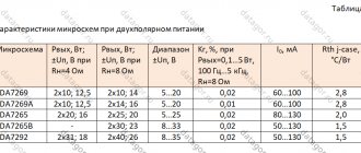
Stabilizer output voltage, V…. ±15 Maximum load current, A…. 20 Stabilization coefficient, not less than…. 1500 Output impedance, no more, Ohm.... 0.01 Voltage on the step-down windings of the power transformer, V.... 2×20
Connection diagram based on LM2940CT-12.0
The stabilizer body can be made of almost any material except wood. When using more than ten LEDs, it is recommended to attach an aluminum radiator to the stabilizer.
Maybe someone has tried it and will say that you can easily do without unnecessary troubles by directly connecting the LEDs. But in this case, the latter will be in unfavorable conditions most of the time, and therefore will not last long or will burn out altogether. But tuning expensive cars results in a fairly large sum.
As for the described schemes, their main advantage is simplicity. Manufacturing does not require any special skills or abilities. However, if the circuit is too complex, then assembling it with your own hands becomes unreasonable.
↑ Parts and analogues
The parts list (BOM) is below.
Details:
VD1, VD2 Schottky diode 16CTQ100 IR (100V, 16A) - 8 pcs., VD3, VD4 Zener diode BZX55C16 (16V, 0.4W), glass - 2 pcs., HL1, HL2 LED FYL-3014HD red d= 3 mm - 2 pcs., HL3, HL4 LED BL-B2141Q G green.d=3 - 2 pcs., VT1 Transistor KT827A (20A; 100V), housing TO-3 - 1 pc., VT2 Transistor KT825A (20A; 100V), case TO-3 - 1 pc., VT3 Transistor BD140, case TO-126 - 1 pc., VT4 Transistor BD139, case TO-126 - 1 pc., VT5 Transistor 2SA1013, case TO-92mod - 1 pc., VT6 Transistor 2SC2383, TO-92mod housing - 1 pc., R1, R3 Resistor -0.25-3.3 kOhm - 2 pcs., R2 Resistor -2-470 Ohm - 1 pc., R4, R7 Resistor -0.25- 130 Ohm - 2 pcs., R5, R6 Resistor -0.25-220 Ohm - 2 pcs., R8 Resistor -0.25-9.1 kOhm - 1 pc., R9, R10 CHIP resistor F2512-1 Ohm, 1W 1% - 2 pcs., R11, R12 Resistor -0.5-2.7 kOhm - 2 pcs., C1...C8 Capacitor 0.1/250V K73-17 - 8 pcs., C9, C10, C23, C24 Capacitor CHIP 1812 0.1µF/100V X7R 10% - 4 pcs., C11...C14 Capacitor 10000/50V 3035+85°C - 4 pcs., C15, C16 Capacitor 47/63V 0611+105°C - 2 pcs., C17 …C20 Capacitor 0.1/63V K73-17 - 4 pcs., C21, C22 Capacitor 47/16V 0511+105°C - 2 pcs., C25, C26 Capacitor 470/35V 0820+105°C - 2 pcs. C27, C28 Capacitor 1/63V K73-17 - 2 pcs., Radiator for VT1, VT2 Printed circuit board 150×70×2 mm - 1 pc.
The power supply uses MLT or foreign MF output resistors with the power indicated on the circuit diagram (Fig. 1).
Capacitors C1 - C8, C17 - C20, C27, C28 type K73-17, imported oxide capacitors. Capacitors C17 - C20 can be replaced with better results with CBB21/MPP made of metallized polypropylene (for example, 0.15 µF, 100 V from the Datagorsk fair). For C27, C28, 1 µF, 100 V (Suntan, polyester) is suitable.
Transistors KT825A and KT827A can be replaced with composite ones (KT819G + KT815G and KT818G + KT814G), while the emitter junctions of powerful transistors KT819G and KT818G must be shunted with resistors with a resistance of 100 - 150 Ohms. It is possible to replace high-power composite transistors with MJ11032 and MJ11033. With a maximum load current of 5 - 7 A, transistors TIP142 and TIP147, as well as BDW42G BDW47G, are suitable.
Transistors VT1, VT2 are mounted on a heat sink with a cooling surface area of 900 sq. cm without heat-insulating gaskets using heat-conducting paste ALSIL-3.
Instead of transistors BD139 and BD140, 2SC3502 and 2SA1380 or BF471 and BF472 are suitable. When replacing, be sure to check the pinout of the transistors.
Transistors VT5, VT6 type 2SA1013, 2SC2383 can be replaced with domestic KT502E, KT503E; KT6116, KT6117 or imported 2N5401, 2N5551; 2SA1145, 2SC2705 and others.
Schottky diodes in bridges VD1, VD2 are replaceable with MBR20200CTG (200 V, 10 A) with a common cathode, or with SR10100 (10 A, 100 V, TO-220-2). In the latter case, the printed circuit board will need to be adjusted.
For consumption currents of more than 2 A, it is necessary to equip the diodes with small radiators and (or) provide them with fan cooling.
With relatively low current consumption (up to 2 A) in diode bridges, you can use high-performance diodes HER505 (5 A, 1000 V), ultra-fast diodes SF56 (5 A, 400 V) or ultrafast STTH5R06FP (5 A, 600 V, TO-220- 2).
The maximum voltage stabilizer current is determined by the power transformer. For example, in the one shown in Fig. In diagram 1, transformer T1 type TPP321 provides a maximum current of no more than 4 A.
Do you need a voltage stabilizer for audio equipment?
A device intended for integration into a household electrical network to obtain specified parameters at the output is called a voltage stabilizer.
Reference. Since 2015, the Russian Federation has adopted a new power grid quality standard that corresponds to the European one. The normal voltage of the household network should now be 230 V (for industrial - 400 V). Frequency – 50 Hz. A deviation from the nominal value is allowed within 10%, that is, in the range of values 207-253 V.
Note: GOST 29322-2014 allows voltage to be supplied to consumers according to old standards - 220 V.
In fact, outdated equipment in many regions of the country and poor-quality wiring lead to significantly greater drawdowns, which could potentially result in breakdown or reduction in the service life of electrical appliances. How even a slight deterioration of the contacts in the distribution panel affects the voltage in the apartment is clearly shown in this video:
Currently, the energy company providing electricity supply services bears responsibility for damage to personal electrical equipment of citizens as a result of over- or under-voltage. However, you will have to seek compensation in court, and you will also have to prove that the actual voltage parameters are significantly higher/lower than normal. And this is a very complex process and not all victims are ready for litigation, which can last several months or even years.
Ultimately, people have to protect their equipment with the help of auxiliary devices - voltage stabilizers.
It is necessary to purchase a stabilizer that is 3-5 times greater than the total power of the electricity consumers connected to it. For example, a voltage regulator for a 150 W amplifier must be rated at least 450 W.
It is worth noting that a surge protector will not save devices from voltage sags; it can only slightly smooth out impulse noise present in the electrical network. But the stabilizer also performs the same function. This means that using a surge protector only makes sense when the user is confident that the electrical current parameters in his apartment or house comply with the standards.
You can read more about when a stabilizer can be replaced with a regular surge protector in this article.
↑ Printed circuit board
The parts of the device, except for the power transformer T1 and powerful transistors VT1, VT2, are mounted on a printed circuit board measuring 150x70 mm (see Fig. 2), made of foil fiberglass laminate.
Rice. 2. Placement of parts on the printed circuit board. The tracks are shown “in the light”, smd elements C9, C10, C23, C24, R9, R10 are installed on the side of the printed tracks
It is advisable to additionally solder the “power” tracks on the printed circuit board on top with tinned mounting wire with a diameter of 0.5 - 0.7 mm.
Device selection
When choosing a stabilizer, take into account the following characteristics:
- Dimensions. The selected stabilizer must be compactly placed in its planned installation location with normal access.
- View. Of the commercially available devices, the most reliable, compact and inexpensive are stabilizers based on small microcircuits.
- Possibility of self-repair. Since even the most reliable devices fail, it is necessary to give preference to repairable stabilizers, radio components for which are commercially available in sufficient quantities and at an affordable price.
- Reliability. The selected stabilizer must provide a constant voltage value without significant deviations from the range declared by their manufacturer.
- Price. For the electrical system of a car, it is enough to purchase a device costing up to 200 rubles.
Also, when choosing a stabilizer, it is necessary to take into account customer reviews, which can be found on specialized forums and websites.
↑ Conclusions
The use of two separate rectifier bridges in the device, in my opinion, is a disadvantage, since compared to one diode bridge we have a twice as high voltage drop across the rectifier diodes, therefore, a lower maximum power.
In addition, the design with two diode bridges has large dimensions. The presence of two independently operating secondary windings of the transformer puts forward the additional requirement that their output voltages be equal.
The only advantage of a circuit with two rectifier bridges is that the maximum voltage on the bridge diode is two times lower, which can play a positive role when choosing Schottky rectifier diodes that have a low reverse voltage, no more than 45 - 200 V.
The described device can be used not only as a power source for UMZCH, but also as a powerful power source for automation devices.
Stabilizer for LEDs on the L7812 chip in cars
The current stabilizer for LEDs can be assembled on the basis of a 3-pin DC voltage regulator (L7812 series). The mounted device is perfect for powering both LED strips and individual light bulbs in a car.
Required components to assemble such a circuit:
- chip L7812;
- capacitor 330 uF 16 V;
- capacitor 100 uF 16 V;
- 1 ampere rectifier diode (1N4001, for example, or a similar Schottky diode);
- wires;
- heat shrink 3 mm.
There can actually be many options.
↑ Sources mentioned
1. Oreshkin V. Power stabilizer UMZCH // Radio, 1987, No. 8, p.
31. 2. A modified version of a low-noise bipolar power supply (see comments 32-36 to the article.) 3. Recommendations from Texas Instruments for constructing power supplies for UMZCH. Thank you for your attention!
Linear stabilizer for LED lamps on cars
So, why do marker bulbs, LED bulbs or other LED bulbs that are in the car burn out so quickly, because they use a regular current-limiting resistor as a driver.
As a rule, LED lighting devices with a power of 10 W and above already use a high-quality pulse stabilizer - the driver does not suffer from such a disease, unlike large, cheap LED lamps.
First, these light bulbs begin to flicker, that is, these are already the first signs of crystal degradation, and then they simply burn out. On average, a simple LED light bulb has a lifespan of one year, sometimes less, sometimes a little more.
Why is this happening?
And this happens because this current-limiting resistor is calculated using a specialized formula (there are many such calculators online on the Internet) and is connected to the appropriate voltage.
Classic model
Classic stabilizers are a large class of devices assembled based on semiconductor parts such as bipolar transistors and zener diodes. Among them, the main function of maintaining the voltage at 12 V is performed by zener diodes - a type of diodes connected in reverse polarity (the plus of the power supply is connected to the cathode of such a semiconductor device, and the minus to the anode), operating in breakdown mode. The essence of how these semiconductor parts work is as follows:
- When the voltage of the power source connected to the zener diode is less than 12 V, it is in the closed position and does not participate in adjusting this characteristic of the electric current.
- When the threshold of 12 Volts is exceeded, the zener diode “opens” and maintains this value in the range specified by its characteristics.
If the voltage supplied to the zener diode exceeds that stated as the maximum by the manufacturer, the device very quickly fails due to the effect of thermal runaway.
In order for any model of zener diode to serve as long as possible, it is recommended to specify, according to its specification, the voltage range and current strength in which it should be operated.
Depending on the connection, there are two versions of the classic stabilizer: linear - the adjusting elements are connected in series with the load; parallel – voltage stabilizing devices are located parallel to the powered devices.
12 volt stabilizer in Balashikha
An “Online Consultant” is available on the seller’s website. To go to the site, click “Go to store”
An “Online Consultant” is available on the seller’s website. To go to the site, click “Go to store”
An “Online Consultant” is available on the seller’s website. To go to the site, click “Go to store”
An “Online Consultant” is available on the seller’s website. To go to the site, click “Go to store”
An “Online Consultant” is available on the seller’s website. To go to the site, click “Go to store”
An “Online Consultant” is available on the seller’s website. To go to the site, click “Go to store”
An “Online Consultant” is available on the seller’s website. To go to the site, click “Go to store”
An “Online Consultant” is available on the seller’s website. To go to the site, click “Go to store”
An “Online Consultant” is available on the seller’s website. To go to the site, click “Go to store”
An “Online Consultant” is available on the seller’s website. To go to the site, click “Go to store”
An “Online Consultant” is available on the seller’s website. To go to the site, click “Go to store”
An “Online Consultant” is available on the seller’s website. To go to the site, click “Go to store”
An “Online Consultant” is available on the seller’s website. To go to the site, click “Go to store”
An “Online Consultant” is available on the seller’s website. To go to the site, click “Go to store”
An “Online Consultant” is available on the seller’s website. To go to the site, click “Go to store”
An “Online Consultant” is available on the seller’s website. To go to the site, click “Go to store”
“One-click ordering” is available on the seller’s website. To go to the site, click “Go to store”
An “Online Consultant” is available on the seller’s website. To go to the site, click “Go to store”
“One-click ordering” is available on the seller’s website. To go to the site, click “Go to store”
An “Online Consultant” is available on the seller’s website. To go to the site, click “Go to store”
“One-click ordering” is available on the seller’s website. To go to the site, click “Go to store”
An “Online Consultant” is available on the seller’s website. To go to the site, click “Go to store”
“One-click ordering” is available on the seller’s website. To go to the site, click “Go to store”
An “Online Consultant” is available on the seller’s website. To go to the site, click “Go to store”
“One-click ordering” is available on the seller’s website. To go to the site, click “Go to store”
An “Online Consultant” is available on the seller’s website. To go to the site, click “Go to store”
“One-click ordering” is available on the seller’s website. To go to the site, click “Go to store”
An “Online Consultant” is available on the seller’s website. To go to the site, click “Go to store”
“One-click ordering” is available on the seller’s website. To go to the site, click “Go to store”
An “Online Consultant” is available on the seller’s website. To go to the site, click “Go to store”
A toll-free number 8-800 is available on the seller's website. To go to the site, click “Go to store”
Do-it-yourself power supply
What kind of homemade power supply is needed?
The power supply can be assembled completely independently. It will operate from a 220 volt network. Thus, through it you can connect a car radio and listen to music in your own garage without disturbing your neighbors. The primary task will be to obtain a constant voltage of 14 V from a 220 V outlet. Everything seems clear, but on the other hand, a car radio with speakers and full volume is a very power-consuming device. Here you need as many amps as possible.
Note. It turns out that a homemade power supply must maintain a constant voltage of 14 V and at the same time be capable of delivering a current of several Amperes, necessary for the normal operation of the entire speaker system.
Simple 220 V mains power supply
Attention. All stabilizers must be placed on the radiator so as not to burn out from overheating. This is a mandatory condition, even taking into account that in the drag-out they write about the protection against short circuits and overheating. As they say, trust, but verify. It’s better to insure yourself in advance, because if it accidentally shorts out, the microcircuit and transistors along with it will go to hell.
- We find a future blank for payment;
- We remove everything unnecessary from there: microcircuits, capacitors, etc.
Note. If the found board has 4 working diodes located at the bottom left, two capacitors and a radiator at the top right, then there is no need to remove them.
- The diodes should be KD203A, although others are possible, as long as they can withstand the current passing through them;
- As for capacitors, one of them should be 2000 µF, and the other should be 100 µF.
Note. We note right away that the capacitor must be selected according to the following principle: the larger its capacity after the diode bridge, the better. In addition, we pay special attention to tension. We try to choose capacitors that are capable of operating in circuits up to 50 Volts.
- Selection of a powerful transformer is the next stage in the work. Under no circumstances should you install a transformer from a radio or various Chinese toys, as well as from other small equipment. The transformer must be full-fledged and have good dimensions.
Note. You can determine whether a given transformer is suitable or not using the passport information. Where there are the most turns in the transformer, there is a primary winding, which must be connected to 220 V and measure the voltage on the secondary windings: it should be within 15-25 Volts.
- After that, all that remains is to select the microcircuit. We take into account what speakers the homemade power supply will work with. If the speakers are small, then the microcircuit can be taken at 3 Amperes;
- We install a stabilizer, for which you need to prepare a seat on the board with fine-grained sandpaper. We just take the skin and clean it;
- The stabilizer is treated with heat-conducting paste KPT-8;
- We place it on the radiator using a clamp;
- We take a soldering iron and solder the entire circuit using the surface-mounting method.
Checking the assembled power supply is the most important and responsible part of the work. If the output is 13.7 Volts, then this is quite enough to drive a couple of small speakers.
- We connect the radio with a homemade power supply. The yellow and red wires go to the positive, the black to the body.
The above instructions will allow you to select or make a power supply for your car radio with your own hands. It will be useful to watch a thematic video review or photo materials. The price of a computer power supply, as mentioned above, is low and you can even find it at home, in a pile of unnecessary hardware.
You can post now and register later. If you have an account, log in to write on your behalf. Note: Your post will require moderator approval before it will be visible.
Related publications
Hello. I have this problem: I have a regular servo with 3 inputs. Plus, minus and pin for control. It is already on my model, glued. But I noticed that the wire that comes out of its body was bent and almost broke. It has not completely broken off, but is already on the border. What can be done? How to delicately fix it?
Good afternoon. I got my hands on a glitchy operator's remote control Aries SP307-R. The symptoms are as follows: reboot, both on its own and when trying to select any item in the menu. Carcass power supply is from 23 to 27 volts. In the unit where it is installed, it is powered by a stabilized 25 volt power supply. I found out that when the power supply increases to 27 volts, the remote control begins to work more stable. But not for long. I opened the beast - inside there is a multilayer board with the index TG765-M-151026. If you look at the picture, on the left is the voltage stabilizer on the UC3844b chip. When a voltage of 23 to 27 volts is applied, the carcass starts. The voltage on the USB connectors on the right is no more than 4.4 volts. Moreover, it floats depending on the applied voltage. I checked all the capacitances around the UC3844b chip. Capacitances 470 microfarads - somewhere around 430-450 microfarads. ESR is somewhere around 0.2-0.3. Capacitances of 220 and 100 microfarads are almost the same as the nominal values. Yes, the containers heat up to 40-45 degrees during operation. I checked the microcircuit: The power fluctuates from 19.7 to 20 volts Vref - 5.19 volts. (should be 5.00) on Rt/Ct stable saw. True, at pin 6 there are not rectangular pulses, but rather strange ones (in the photo) I understand that the hat is in the stabilizer, but I can’t figure out where. Can someone recommend something?
Guys, good morning, I bought a skad 210 machine for wheel balancing, but it turned out to be a power supply, I need a power supply diagram
Computer block
Connecting the car radio to the computer power supply
Before getting down to business, you need to have the car radio itself and a computer power supply on hand (both AT and ATX formats are suitable).
Note. You don't have to buy a computer power supply. At every house you can find a pile of computer hardware, which includes old units.
To be precise, the power supply can be found in three ways:
- Pull it out of an old computer that has not been used for a long time;
- Buy used radio products on the market for mere pennies;
- Repair a faulty computer unit.
Connecting a car radio to the computer power supply
How to fix a faulty unit
This is easy to do if you follow the instructions below:
- We try to turn on the power supply.
Note. As a rule, most used computer units are fully functional, but have certain defects, such as low voltage on one channel or lack of voltage on any output.
12V power supply for car radio
- Another way to “revive” the power supply involves forcibly discharging high-voltage capacitors of the electrolytic type of the input rectifier. To do this, you need to connect a resistor (100-200 kOhm) in parallel with the capacitor for a few seconds.
Note. It is extremely forbidden to hold the resistor with bare hands, as you can receive an electric shock, although light, but quite noticeable. We hold it with special tweezers or some other instrument.
- We attach great importance to the capacitors of the output rectifiers. We pay attention to whether they are swollen or have a serif gap. If this is the case, replace the capacitors with new ones;
- Some people advise painting the old block with some kind of spray paint.
Connecting a car radio at home
Many of us have old car radios in our homes or garages that sit idle and gathering dust. They can all be given a “second life” as a regular receiver or music center. The sound quality and power of such devices is higher than that of portable or stationary ones.
How to connect a car radio at home
The main thing in connection is making a power supply or using a ready-made one (or a battery instead). Connection options are given below:
We decided on the power source. Now let’s make the connection itself, it is performed according to the following diagram:
How to connect in a car
We do not connect the antenna power and backlight control wires. We connect the battery and ignition switch together and connect to positive, ground to negative.
The speakers are suitable from any music center with an internal resistance of 4–16 Ohms, or car speakers with homemade housings.
Legends and myths
If you type the phrase “buy a voltage stabilizer” in the search bar on your PC, you will get a kilometer-long list of sellers who will assure that their super-precise devices are necessary for all users without exception. In most cases, prices range from five to six figures.
But upon deeper analysis, it turns out that not everything is so simple.
- Precise adjustment of the voltage parameter is a good marketing ploy for the manufacturers of these same stabilizers. They often indicate ranges of ±2, 4, 6% and even 0.5% and sell devices at exorbitant prices. In reality, for the vast majority of equipment, a real voltage of 220-230 V ± 10% is sufficient. Almost all equipment has a margin of “strength”; in extreme cases, you can familiarize yourself with the recommendations of the audio equipment manufacturer from the device’s passport;
- All stabilizers improve sound quality - this is not true, moreover, a stabilizer can worsen the sound signal. This is the problem with many electronic stabilizers created on the basis of thyristors and triacs. The reasons are radio interference emitted by such semiconductors. This fact has been proven many times when connecting an oscilloscope to the output of stabilizers of this type.