If you have a radio tape recorder lying around, you can make a good music center out of it yourself. And if desired, a home cinema. It’s enough to find good acoustics for it and find an alternative 12 V power source. Let’s list some ways to connect a radio at home from a 220 volt network.
Home cinema from a radio
What to connect where in the car radio
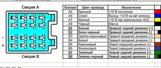
Output blocks on radios can vary in size and wire layout. The good news is that manufacturers try to adhere to certain rules in choosing colors for each system. And you can take advantage of this.
Connectors on radios
Most often, the colors of the wires for each of the systems are as follows:
- Yellow and red - 12 volt power supply. Yellow - from the battery, red - from the ignition, this is control.
- White, purple, green and gray (and their variants with black or white stripes) - for the audio system.
- Black is mass.
- Blue - antenna output.
The colors of the audio system connection wires may vary slightly. But for food and weight these will be the colors.
A standard connection diagram that makes it easy to understand what needs to go where
We will deal with power supply further, and in this connector we will talk about connecting the audio system and antenna. With the antenna everything is simple - blue wire. Temporarily you can “hang” here even just a piece of wire, or you can use a purchased or homemade antenna .
An audio system is rarely complex. Most often they install one or two columns. We connect them to any pair of wires from the list. A pair is lilac and lilac-black or lilac and white, for example.
The primary color indicates that this pin is positive, "+". A white or black stripe indicates that the output is negative “-“. This must be taken into account when connecting speakers. They will definitely indicate the plus and minus of the connection.
We connect one of the wires of the pair to one input of the speaker, the second to the other. After power is applied, sound will appear in the speakers.
How best to connect wires
Depending on the condition in which you received the car radio, it may have an output block, or it may have a bundle of wires. Both options are workable. The second option is preferable, as it is easier to make a high-quality connection. If you no longer plan to use this device in your car, it is easier to cut off the ISO block. Well, or those wires that need to be cut off from the block.
Connecting wires when connecting a car radio
If you decide to keep the block, when connecting, we strip the conductors and insert them into the sockets opposite the wires of the desired color. If you chose the “wires without block” option, the ends of the required conductors must be stripped of insulation (0.8-1.0 cm). Then, during operation, the connected wires are twisted tightly. If you have a soldering iron, it is better to solder all the twists after testing - when you are sure that everything works.
When they are convinced that the radio is working, the connections are isolated. You can use electrical tape, but it is safer to use heat shrink tubing.
Is it possible to make a 12V power supply yourself?
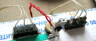
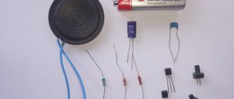
Is it possible to build a 12V - 220V power supply with your own hands? It is possible to make such a device, but this process requires certain skills and experience, so be careful when performing this task. For manufacturing you will need a 12 volt transformer unit, as well as four diodes with a 470 uF 25 volt capacitor device. Any diode elements can be used, since the voltage will be low. As for the capacitor device, a minimum of 25 volts will be required, since ultimately it will output the required 12 volts.
How to make a power supply with your own hands:
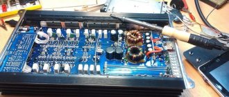
- Diode elements have polarity, in fact, just like a capacitor device. If you see a mark in the form of a strip on the contact, then this is a positive terminal, but if there is no strip, then the terminal is negative. Take two diode elements and connect them to each other according to the plus-minus circuit, do the same with the second pair. The elements themselves can either be soldered or simply twisted. We will demonstrate the simplest manufacturing method - if necessary, you can build the device on a board or in a case.
- After this, you will need to connect two solders or twists of diodes to each other. When connecting, the positive terminal on one of the solders must be connected to the positive terminal on the other solder. Do the same with the negative contacts - the minus of one solder is connected to the minus of the other. So you made a diode bridge.
- Then you will need to connect the output from the transformer device to the constructed diode bridge. One contact from the device should be connected to the plus-minus contact on the bridge, the second contact is similarly connected to the same output. At this stage, the plus-plus and minus-minus contacts are still free.
- Once these steps are completed, you will need a capacitor that also has polarity on it. As a rule, on such devices only the negative contact is marked; accordingly, the terminal that is not marked will be positive. The capacitor element should be connected to the diodes. The terminal of the plus-plus diodes is connected to the positive contact of the capacitor, and the minus-minus diodes must be connected to the negative terminal.
- Next, you will need two conductors, preferably they have different colors - one of them is connected to the positive terminal, and the other to the negative terminal. For example, in the photo we used a red conductor to connect to the positive terminal (plus-plus) on the diode bridge, and a blue one to the negative terminal, that is, minus-minus. The positive output has the plus from the capacitor device, and the negative output has its minus.
- At this point the assembly procedure can be considered complete. Now all you have to do is measure the voltage. If the operating parameter is 16.3 volts, then there is no need to worry, since this is a normal value for the voltage of a power supply running idle. When a load is placed on the block, it will eventually produce 12 volts.
Photo gallery “Independent production of power supply”
1. Soldering of four diodes - bridge 2. Connecting the diode bridge to the transformer winding 3. Connecting the capacitor to the resulting circuit 4. At the final stage, connect the wires
Power supply for the radio: how many volts and watts and where to get them
When connected normally in a car, the radio operates on 12 volts DC. This is exactly the voltage you need if you want to use it at home. Power consumption depends on the model and audio system, but in most cases it is up to 150 W.
We're using simple physics here. Power calculation formula P=UI. Hence 12V*10A=120 W. 10 amps is the size of the radio fuse. That is, this is the maximum current consumption of the radio. In reality it is somewhat smaller.
If the radio says 4*50 W (200 W), this is not entirely correct. From the formula it turns out that the current consumption is 200 W/12V≈16.7 A. The amplifiers used can indeed provide such output power, but at a voltage of 18 volts or a load of 2 Ohms.
Connecting the radio from the computer power supply
Similar parameters can be obtained from the following devices:
- Voltage converter 220/12 V.
- Power supply for a computer.
- Chargers for various devices - laptops, phones, LED lamps, small household appliances.
- 12 V batteries.
When choosing a power source for your car radio, also look at the power. If it’s too weak, it won’t work or won’t work for long. So, at least when connecting for the first time, supply power through a fuse.
Connection diagram of the car radio to the car ignition switch
Connecting power to the car radio itself is simple. When connected normally in a car, the yellow one receives power from the battery, the red one receives positive from the ignition switch. Just twist them together and connect the power source to this twist, whatever it may be.
Is it possible to make a 12V power supply yourself?
Is it possible to build a 12V - 220V power supply with your own hands? It is possible to make such a device, but this process requires certain skills and experience, so be careful when performing this task. For manufacturing you will need a 12 volt transformer unit, as well as four diodes with a 470 uF 25 volt capacitor device. Any diode elements can be used, since the voltage will be low. As for the capacitor device, a minimum of 25 volts will be required, since ultimately it will output the required 12 volts.
How to make a power supply with your own hands:
- Diode elements have polarity, in fact, just like a capacitor device. If you see a mark in the form of a strip on the contact, then this is a positive terminal, but if there is no strip, then the terminal is negative. Take two diode elements and connect them to each other according to the plus-minus circuit, do the same with the second pair. The elements themselves can either be soldered or simply twisted. We will demonstrate the simplest manufacturing method - if necessary, you can build the device on a board or in a case.
- After this, you will need to connect two solders or twists of diodes to each other. When connecting, the positive terminal on one of the solders must be connected to the positive terminal on the other solder. Do the same with the negative contacts - the minus of one solder is connected to the minus of the other. So you made a diode bridge.
- Then you will need to connect the output from the transformer device to the constructed diode bridge. One contact from the device should be connected to the plus-minus contact on the bridge, the second contact is similarly connected to the same output. At this stage, the plus-plus and minus-minus contacts are still free.
- Once these steps are completed, you will need a capacitor that also has polarity on it. As a rule, on such devices only the negative contact is marked; accordingly, the terminal that is not marked will be positive. The capacitor element should be connected to the diodes. The terminal of the plus-plus diodes is connected to the positive contact of the capacitor, and the minus-minus diodes must be connected to the negative terminal.
- Next, you will need two conductors, preferably they have different colors - one of them is connected to the positive terminal, and the other to the negative terminal. For example, in the photo we used a red conductor to connect to the positive terminal (plus-plus) on the diode bridge, and a blue one to the negative terminal, that is, minus-minus. The positive output has the plus from the capacitor device, and the negative output has its minus.
- At this point the assembly procedure can be considered complete. Now all you have to do is measure the voltage. If the operating parameter is 16.3 volts, then there is no need to worry, since this is a normal value for the voltage of a power supply running idle. When a load is placed on the block, it will eventually produce 12 volts.
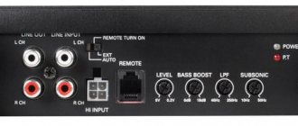
Connect via computer power supply
Any computer power supply produces +12 V and at least 10 amperes in this circuit. This is the voltage that needs to be supplied for the car radio. The first thing to do is start the power supply. In order for it to work when plugged into the network, you need to short-circuit the black and green leads. They are output to the power supply connector for 4 or 24 outputs. They must be connected with a jumper. Or cut off the necessary wires, strip the insulation, twist them together and insulate them.
Stages of work, wires and pads
When the power supply is turned on, the fan should start working.
Where to get 12 V on the computer power supply
We take the power supply connectors and look for the yellow wire. Usually there is a large connector and several small ones. The “large connector” can have 12 or 24 outputs. Depends on the block model. But the yellow wire is still there.
Where to look for 12 V on a computer power supply
The small connectors that go to peripheral devices also have a yellow wire and 12 V. You can take the power from there.
This is what a computer power supply looks like
You can make sure that it is working correctly by taking a multimeter and measuring the voltage on the yellow wire. On the multimeter we set the DC voltage measurement to 20 volts.
The stripped wire can be inserted into the block. But it’s better to cut off the wire, strip it and connect it to the desired conductor from the radio.
The second black wire we need is negative.
All this work - removing, cleaning, connecting - is carried out with the power supply unplugged.
How to connect wires
On the radio, power is supplied to the red and yellow wires. If you have a connector, you must either insert the wires into the appropriate sockets, or cut off the block and strip the necessary wires. If you decide to cut off the block, twist the wires that supply power to the car radio together. And we connect them to the yellow wire from the computer power supply.
We connect the black wire of the radio to the black wire from the power supply.
After turning on the power and connecting the speakers, you can enjoy music at home, in the garage or in the country house
If the block has not been cut off, you need to install a jumper between the red and yellow wires (you can use a piece of wire with stripped ends). Plug the yellow wire from the power supply into one of the connectors with a jumper. So it turns out that power is supplied to both inputs at once.
What is it for
The price of a good car radio is lower than the price of a music center. However, its sound quality may not be much lower. It happens that a car enthusiast purchased a car along with it, then decided to install a system in its place that is superior to the standard one, and install the freed one at home and connect it to a 220 V network.
Sometimes an old radio along with speakers is stored in the garage, and the owner decides to connect it in the garage to listen to music while repairing the car.
In addition, sometimes there are times when you need to check the serviceability of the car radio. To power it, you will need a 12 volt electricity source.
Expert opinion
Alexey Bartosh
Specialist in repair and maintenance of electrical equipment and industrial electronics.
Ask a Question
The simplest and most cost-effective option in such cases is to use a power stabilizer from the computer. You can get it from an old, no longer needed PC or buy it at a flea market. This will make it possible to install the radio at home without a battery.
Connection via adapter/charging
Most chargers or adapters for small appliances provide 12 volts. But you also need to select the current that this device produces. If you have a passport for the radio or a nameplate on it, look at the exact data there.
The car radio requires 12 V and 5-6 A to operate.
Most chargers or adapters for small appliances provide 12 volts. But you also need to select the current that this device produces. If you have a passport for the radio or a nameplate on it, look at the exact data there.
If there is nowhere to get the data, you can focus on the “average”. Typically, a car radio in normal operating mode consumes 5 A. At maximum load, perhaps, the consumption is 10 A. But with such a connection, you cannot squeeze the maximum out of it. So, we are looking for a network adapter or charger that produces 12 V and 5–6 A.
If you find an adapter or charger with suitable parameters, after five to ten minutes the car radio will work from the 220 network
Most of the procedure for connecting a car radio at home is outlined above. We will describe only the immediate actions.
If you find an adapter or charger with suitable parameters, after five to ten minutes the car radio will work from the 220 network
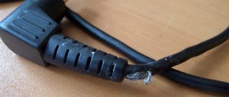
- Cut off the plug. The part that we insert into the equipment from the charger/adapter/adapter/power supply.
- We separate the conductors, being careful not to damage the insulation.
- Use a multimeter to determine plus and minus. You can often find a central wire and braid in the cable. Everything here is just a braid - this is a minus.
- We connect them to the power inputs of the car radio.
- We plug in 220 volts and check how it works.
If you don’t want to cut off the plug, you can simply strip the wires at some distance and draw conclusions. But after checking it is better to insulate the connections.
Another option is not to cut or clean anything. You can simply connect the wires to the plug. The “+” wire is stuck into the central hole, and the minus is the external contact.
Expert recommendations
Things to consider when performing this task:
It is advisable to use a ready-made and efficient power supply unit, rather than making it yourself. Of course, if you understand how to make a power supply, you can build it yourself. But practice shows that homemade devices are usually less powerful. Moreover, when making your own, you must make sure that you are using a working transformer device and diodes. You need to make sure of this at the initial stage. Before you start connecting, be sure to check the board of the unit, as well as the capacitors on it
The capacitor elements should not be swollen or damaged; if this is the case, they will need to be resoldered. Strictly follow the above instructions to correctly solder all the elements for connection. It is important that the speakers used are working. It happens that the audio system works with interference and noise, and the car owner, thinking that the reason is due to errors made during assembly, begins to check and repair the power supply
In this case, it is the speakers that are inoperative. If you make mistakes when connecting the wires from the speakers, the speakers will also work with interference.
How to turn on via a step-down transformer
A simple rectifier on a step-down transformer from a 220 V network
The implementation of this option is more difficult, but for those who love to tinker, it will not be difficult. We won’t tell you how to wind a transformer. We assume that you already have it and with the necessary parameters. Namely:
- input voltage 220–230 V, output - 12 V;
- power - from 120 watts depending on the audio system;
- current up to 10 A.
At its output we will have 12 V AC, and the car radio is powered by DC. Therefore, this tension must be straightened. You can assemble an elementary circuit using a diode bridge and a capacitor.
Diodes, for example, KD226, it is better to set the capacitor at 4700 μF to reduce ripple. Before connecting, check the output voltage parameters. Without load it can be slightly higher and amount to 14 - 15 volts.
Extraction of hornblende
On the territory of Russia, the soil of Primorye is rich in volcanic and igneous rocks.
This is where hornblende is mined. Stone is also formed in foreign countries. The most valuable and large crystals are brought from Vesuvius.
In addition to Italy, Norway is famous for snag, where mining is carried out in the Arendal area. But the largest crystals are brought from Bohemia. Czech samples are usually extracted from the Czernoszyn tuffs.
Collectible hornblende crystals have also been discovered in Burma. All types of units are found here. Crystals of the minerals of the group are prismatic and columnar with a hexagonal cross-section. The “full set” is also observed in Azerbaijan.
True, many of the hornblende outcrops here have been eroded. The weathering process transforms the stone into a mixture of clay minerals.
Several iron hydroxides are formed. The most valuable result of weathering is opal.
Rechargeable battery for powering the car radio
Another possible power source is a rechargeable battery. Not just the one for cars, but like the one for screwdrivers or other equipment. You can also supply power from an old car battery, but this is an option for the garage. At home we need something more environmentally friendly and safe.
Connection diagram of the car radio to the battery
There are, of course, ready-made units with a voltage of 12 - 14 volts. Ideal if you have other battery-powered equipment or an old case from a non-working battery with sagging banks. If it does not hold a charge, you need to change banks. Read more about this assembly in the article about battery restoration.
Screwdriver battery