INVERTER 1
This inverter is designed only to power a subwoofer amplifier using a lanzar circuit. Output voltage +/-65 Volts. The inverter does not have output voltage stabilization, but despite this, I did not observe any serious voltage surges. The inverter was built using a classic push-pull circuit using a PWM controller on a TL494 . The transformer was wound on two rings of the 3000NM brand (Evgeniy, thank you for helping out and sending the rings from the other side of the world), the dimensions of the rings are 45*28*8. If possible, use ferrite grade 2000NM, it will result in fewer losses in the transformer. I didn’t glue the rings together, I just wrapped them with clear tape. I didn’t round the edges of the ring, I just wrapped the core with a strip of fiberglass in two layers before winding. Fiberglass is not afraid of overheating and provides fairly good winding insulation, although in such industrial-style inverters the windings are never isolated from each other, since the voltage is not so high.
Winding was done with two completely identical busbars, each busbar consisting of 12 wire strands with a diameter of 0.7 mm. Before winding, we take a control wire, we will use it to find out how long the tire is needed. The control wire can be of any type, of any cross-section (for convenience, select a diameter of 0.3-1 mm). So, take the control wire and wind 5 turns around the ring, stretching the turns evenly throughout the ring. Now we unwind the winding, measuring the length, let’s say the length of the wire is 20 cm, therefore, to wind the main winding, the wire must be taken with a margin of 5-7 cm, i.e. 25-27 cm, of course, the length is not exact and is given only as an example. Now let's move on. Since our primary (power) winding consists of two completely similar arms, we need 24 strands of 0.7 mm wire of the same length. Next you need to assemble the tires from 12 cores, twist the ends of the cores and proceed to the winding process.
Different sources provide different winding technologies; this method differs in that it allows you to obtain the most equivalent windings. We wind it with two tires at once; it is advisable to use a harness for convenience, but I wound it without it. We wind 5 turns around the entire ring as carefully as possible, in the end we get 4 bends. To ensure the durability of the turns, we insulate the winding, the test insulation can be anything - tape, electrical tape, thread, etc., as long as the winding holds, if you are sure of the correctness of the winding, then you can install the final insulation (in my case, again fiberglass). Now you need to phase the windings, connecting the beginning of the first half-winding (arm) to the end of the second, or vice versa, the beginning of the second, to the end of the first. At the junction of the windings there is a tap from the middle; power plus 12 Volts is supplied to it according to the circuit. The secondary winding is wound and phased according to the same principle as the primary. The winding consists of 2x24 turns, wound with two tires. Each bus consists of 5 strands of 0.7 mm wire.
The diode rectifier is assembled from 4 diodes of the KD213A . These are pulsed diodes with a reverse voltage of up to 200 Volts, they feel great at frequencies of 50-80 kHz (although they can operate at frequencies up to 100 kHz), and the maximum permissible current of 10 Amps is what you need. The diodes do not require additional cooling, although heat generation may occur during operation.
I used ready-made chokes in the output circuit, from computer power supplies. The chokes are wound on a ferrite rod (length 1.5-2 cm, diameter 6 mm). The winding contains 5-6 turns, wound with 2-2.5 mm wire; for convenience, you can wind it with several strands of thinner wire. I took smoothing electrolytes with a voltage of 100 Volts 1000 μF, they work with a large margin. As a result, there are 4 such capacitors in the arm on the inverter board, two more similar ones are on the board of the Lanzar amplifier , i.e. the total capacitance of the filters in the arm is 5000 μF. Before and after the chokes there are film capacitors with a voltage of 100 Volts; their capacitance is not particularly critical and can be in the region of 0.1-1 µF.
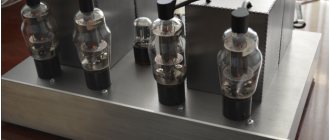
High input impedance and shallow feedback are the main secret of warm tube sound. It's no secret that the highest quality and most expensive amplifiers, which belong to the HI-End category, are manufactured using tubes. Let's understand what a quality amplifier is? A low-frequency power amplifier has the right to be called high-quality if it completely repeats the shape of the input signal at the output without distorting it; of course, the output signal is already amplified. On the Internet you can find several circuits of really high-quality amplifiers, which can be classified as HI-End and do not necessarily require tube circuitry. To obtain maximum quality, you need an amplifier whose output stage operates in pure class A. Maximum linearity of the circuit gives a minimum amount of distortion at the output, therefore, in the design of high-quality amplifiers, special attention is paid to this factor. Tube circuits are good, but not always available even for self-assembly, and industrial tube UMZCHs from brand manufacturers cost from several thousand to several tens of thousands of US dollars - this price is certainly not affordable for many.
The question arises: is it possible to achieve similar results from transistor circuits? the answer will be at the end of the article.
There are quite a lot of linear and ultra-linear circuits of low-frequency power amplifiers, but the circuit that will be considered today is a high-quality ultra-linear circuit, which is implemented with only 4 transistors. The circuit was created back in 1969 by British audio engineer John Linsley-Hood. The author is the creator of several other high-quality circuits, in particular class A. Some experts call this amplifier the highest quality among transistor ULFs, and I was convinced of this a year ago.
The first version of such an amplifier was presented on our website. A successful attempt to implement the circuit forced me to create a two-channel ULF using the same circuit, assemble everything in a housing and use it for personal needs.
Features of the scheme
Despite its simplicity, the scheme has several features. Correct operation may be disrupted due to incorrect board layout, poor placement of components, incorrect power supply, etc.
It is the power supply that is a particularly important factor - I strongly advise against powering this amplifier from all kinds of power supplies; the best option is a battery or a power supply with a battery connected in parallel.
The amplifier power is 10 watts with a 16 Volt power supply into a 4 Ohm load. The circuit itself can be adapted for 4, 8 and 16 Ohm heads.
I created a stereo version of the amplifier, both channels are located on the same board.
Since the original transistors of the circuit could not be found, analogues had to be used. The entire base is domestic. The first transistor (where the sound is actually formed) was made of germanium; it sounds better by ear. You can use any P-N-P low-power germanium transistors MP25 and the like. If desired, the transistor can be replaced with KT361 or no less noisy ones.
The second one is intended for driving the output stage, I installed KT801 (it was quite difficult to get hold of it.
In the output stage itself, I installed powerful bipolar switches of reverse conduction - the KT803 received undoubtedly high-quality sound with them, although I experimented with many transistors - KT805, 819, 808, and even installed powerful composite ones - KT827, with it the power is much higher, but the sound is not compare with KT803, although this is just my subjective opinion.
An input capacitor with a capacity of 0.1-0.33 μF, you need to use film capacitors with minimal leakage, preferably from well-known manufacturers, the same with the output electrolytic capacitor.
If the circuit is designed for a 4 Ohm load, then you should not increase the supply voltage above 16-18 Volts.
I decided not to install a sound regulator; it, in turn, also affects the sound, but it is advisable to install a 47k resistor parallel to the input and minus.
The board itself is a breadboard. I had to tinker with the board for a long time, since the lines of the tracks also had some influence on the sound quality as a whole. This amplifier has a very wide frequency range, from 30 Hz to 1 MHz.
Setup couldn't be easier. To do this, you need to use a variable resistor to achieve half the supply voltage at the output. For more precise settings, it is worth using a multi-turn variable resistor. We connect one multimeter lead to the minus power supply, put the other one to the output line, i.e. to the plus of the electrolyte at the output, thus, slowly rotating the variable we achieve half of the power supply at the output.
The quiescent current of the amplifier is 0.5-0.7A and this is quite normal for class A. The efficiency of the circuit is no more than 25%, all the main power of the power supply turns into unnecessary heat, which is released by the transistors of the output stage, so they need intensive cooling, possibly You will also need a cooler.
All electrolytic capacitors are selected for 25 Volts, although 16 is possible.
About the sound.
Well, what can I say, I have never heard a purer sound, even from some tube amplifiers, maximum detail of each note, it seems that a live orchestra is playing, divinely pure - and that says it all. Definitely, this circuit can sound better than many tube amplifiers. Without applying a signal to the input from the acoustics, there are no squeaks or noises, even very quiet ones, and any amplifier I know is not capable of this. I compared the sound with LM1875, with TDA 2030, even with STK412-010 and the Lanzar circuit - Linsley Hood is much better and cleaner.
In the future, we plan to assemble a stylish case for this amplifier, but more on that another time.
Printed circuit board
Sincerely - AKA KASYAN
STARTING THE FIRST PSU INVERTER
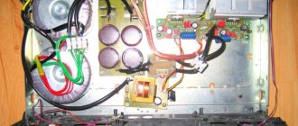
Before starting the inverter, carefully check the correct installation. Low-power transistors BC556/557 can be replaced with the domestic analogue KT3107, BC546 with KT3102 or any others with similar parameters. Field switches should not heat up during operation without an output load, and with a load the heating of the arms should be uniform. The last stage is heat removal. In my case, the field-effect transistors are mounted on a heat sink from the computer power supply, through mica spacers and insulating washers.
The circuit implements remote control (REM), i.e. the main, power plus and minus are always connected to the amplifier, and in order for the circuit to start, a plus is applied to the REM point, the BC546 transistor opens and power is supplied to the generator and the inverter’s operating cycle begins. Plus, the remote can be supplied from the car radio, or you can install a small toggle switch in the car that can be used to turn the amplifier on and off.
If you have any problems...
Problem . It happens that the field switches fail the first time they are turned on.
Cause and remedy . The primary winding is incorrectly phased or the transistors are defective. If you are sure of the correct installation and the serviceability of all components, then most likely the primary winding of the transformer is incorrectly phased. To do this, we turn off the secondary circuit, that is, the load that is connected to the secondary winding and start the transformer again (often, problems can arise on the secondary circuits), if everything is the same, then we check the transistors for serviceability, they will most likely be “dead,” replace them and We phase the transformer correctly.
Problem . When turned on, one of the pairs of transistors overheats, the second pair is cold.
Cause and remedy . First, we check the presence of rectangular pulses on pins 9 and 10 of the microcircuit; if everything is ok, then we check the connection of diodes and low-power transistors. This problem arises for two reasons - incorrect connection of low-power driver transistors or unequal arms of the primary winding.
INVERTER 2
The circuit and printed circuit board of the second inverter are completely similar to the first. The output voltage for powering the OM is 2x55 Volts (+/-55V). The secondary winding this time is wound with 6 strands of 0.8 mm wire and consists of 2x28 turns, wound using the same technology as in the case of the first inverter.
Please ensure that the primary and secondary windings are wound IN THE SAME DIRECTION!
The other secondary is intended to power the amplifier block based on LM1875 microcircuits. The winding consists of 2x8 turns, wound with 4 strands of 0.8 mm wire. After assembling the inverter, we carefully check the installation for errors; if there are none, then we take a multimeter and check the secondary circuits for short circuits.
FIRST TURN ON
The first start-up of the inverter should be done from a laboratory power supply with short-circuit protection, and at the time of start-up the protection may erroneously work if the unit is low-power; in my case, a converted power supply with a current of 3.5 A was used. The inverter no-load current is 170-280 mA, depending on the correct calculation of the transformer, the operating frequency of the generator and the type of field switches, the snubber resistor plays a significant role, in my case I had to play with it a little to reduce the consumption of the circuit.
During idling, there should be no heat generation on the keys; if there is any, then there is an installation problem or a non-working component. Before starting, wash the board from fluxes; you can use acetone or solvent for this. And now let’s get down to the UMZCH unit itself...
After successfully starting the power supply, we move on to the most interesting part of the design - the audio power amplifier block. Including a low-pass filter for the subwoofer and a stabilization module.
AMPLIFIER FOR SUBWOOFER ACCORDING TO LANZAR CIRCUIT
Well, what can we say about one of the most repeated power amplifier circuits - the Lanzar circuit was developed back in the 70s of the last century. On a modern high-precision elementary base, Lanzar began to sound even better. In theory, the circuit is excellent for wideband acoustics; distortion at half volume is only 0.04% - full-fledged Hi-Fi .
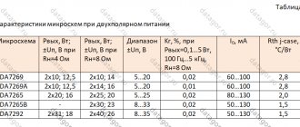
The output stage of the amplifier is built on a pair of 2SA1943 and 2SC5200, all stages are assembled on complementary pairs that are as close as possible in parameters, the amplifier is built entirely on a symmetrical basis. The rated output power of the amplifier is 230-280 watts, but much more can be removed by increasing the input supply voltage. The values of the limiting resistors of the differential stages are selected based on the input voltage. Below is the table.
| Power, V | Resistance, kOhm |
| ±70 | 3,3…3,9 |
| ±60 | 2,7…3,3 |
| ±50 | 2,2…2,7 |
| ±40 | 1,5…2,2 |
| ±30 | 1,0…1,5 |
These resistors are selected with a power of 1-2 watts; during operation, heat generation may be observed on them.
The regulating transistor was replaced with a domestic KT815; at that time there was no other one at hand. It is designed to regulate the quiescent current of the output stages; it does not overheat during operation, but is mounted on a common heat sink with the transistors of the output stage.
It is advisable to do the first start of the circuit from the mains power supply; connect a 100-150 watt incandescent lamp in series with the mains winding of the transformer; if there are problems, then burn a minimum of parts. In general, Lanzar’s circuit is not critical to the installation and components; I tried it even with a wide range of components used, using domestic radio components - the circuit shows high parameters even in this case. Lanzar's circuit diagram has two main versions - on bipolar transistors and using field switches in the penultimate stage, in my case the first version.
The second pre-output stage operates in pure class “ A ”, so during operation the transistors overheat. Transistors of this cascade must be installed on a heat sink, preferably a common one, do not forget about insulation - mica plates and insulating washers for screws.
A correctly assembled circuit starts up without any problems. We make the first launch with the INPUT SHORT-CORTED TO GROUND, i.e. The amplifier input is connected to the middle point from the power supply. If nothing explodes after launch, then you can disconnect the input from the ground. Next we connect the load - the speaker and turn on the amplifier. To make sure the amplifier is working, just touch the bare input wire. If a peculiar roar appears in the head, then the amplifier is working! Next, you can strengthen all the power parts with heat sinks and send an audio signal to the amplifier input. After 15-20 minutes of operation at 30-50% of the maximum volume, you need to adjust the quiescent current. The photo shows everything in detail; it is advisable to use a digital multimeter as a voltage indicator.
Amplifier output power measurement
How to set the quiescent current
LPF AND STABILIZATION UNIT
The low-pass filter and adder are built on two microcircuits. It is designed for smooth adjustment of phase, volume and frequency. The adder is designed to sum the signals of both channels to obtain a more powerful signal. Industrial high-power auto amplifiers use exactly this principle of filtering and summing the signal, but the adder can, if desired, be excluded from the circuit and make do with only a low-pass filter. The filter cuts off all frequencies, leaving only a limit between 35-150 Hz.
Phase adjustment allows you to match the subwoofer with speaker systems, in some cases it is also excluded. This unit is powered by a stabilized bipolar voltage source +/-15 Volts. Power can be provided using an additional secondary winding, or you can use a bipolar voltage stabilizer to reduce the voltage from the main winding. For this purpose, a bipolar stabilizer has been assembled. Initially, the voltage is reduced by zener diodes, then amplified by bipolar transistors and supplied to linear voltage stabilizers of type 7815 and 7915. At the output of the stabilizer, a stable bipolar power supply is formed, which powers the adder and low-pass filter unit.
Stabilizers and transistors can get hot, but this is quite normal; if desired, they can be mounted on heat sinks, but in my case there is active cooling by a cooler, so heat sinks were not useful, and besides, the heat dissipation is within normal limits, since the low-pass filter unit itself consumes very little.
Power amplifier Only Music 2.7 (ex “slap in the face mikruham”) [2018]
Prologue. The idea of creating this amplifier dates back to the development of the Only Music 3 (OM3) amplifier. Then the plan was to make, in addition to the main version of OM3, a simplified version of it. I abandoned this idea, but after some time I decided to return to it. This is due to the excessive complexity of replicating OM3, which caused many difficulties for those wishing to duplicate the amplifier. This is what prompted the creation of a new amplifier and a return to the original concept of the series - maximum quality with minimal complexity and dimensions.
Concept. As mentioned above, the new amplifier pursues the old concept laid down in the “slap in the face mikruham 2” (OM2). When developing the amplifier, the goal was to achieve maximum repeatability, reliability and stability of the circuit, as well as to minimize the diversity of the used element base and exclude less common items from the list of used radio components. The qualitative parameters of the amplifier also did not go unnoticed - the new amplifier is not inferior to the OM3, and in most respects even surpasses it. Thanks to the emergence of a huge number of printed circuit board manufacturers and their active competition among themselves, a huge number of profitable offers have appeared for the production of factory printed circuit boards in small quantities, so I decided to place a bet on a double-sided printed circuit board designed for factory production. However, I did not refuse a single-sided printed circuit board, so I also made a version of the printed circuit board designed for home production using “laser ironing technology” (LUT). The dimensions of the factory printed circuit board are exactly the same as those of the original printed circuit board for OM2 - 100x67mm, and the dimensions of the single-sided board are slightly larger - 100x73mm.
Name. You're probably wondering: why 2.7 and not 3.5 for example? In fact, everything here is extremely simple - in this way I wanted to show that this amplifier in its concept is closer to OM2 than to OM3.
Scheme. Once again I decided not to change traditions and use the classic Lin topology. The idea for the voltage amplifier (VA) circuit, which has undergone significant modifications and improvements in this amplifier, was borrowed from the well-proven BackBen amplifier, my design. The differential cascade (DC) was supplemented with a cascode, which made it possible to unload the input pair of transistors in terms of power and voltage. This made it possible to use low-voltage, low-noise, superbeta transistors at the input, which, together with a decrease in the collector-emitter voltage of the input pair and the power dissipated by them, made it possible to significantly reduce the noise level at the output of the amplifier. The ability to adjust the “zero” available in the OM2 amplifier was returned, which allows you to accurately balance the differential stage. Stable current generators (GST) for the differential stage and the voltage amplifier stage (VCA) are independent of each other and have independent reference voltage sources. Capacitor C12 increases the stability of the GTS and significantly reduces the ripple of their reference voltage. A fundamentally different method of frequency correction of the amplifier was used compared to those used in OM2 and OM3, which made it possible to obtain much greater gain with an open loop of the general negative feedback than in OM3 and much greater stability than in OM2. During the development of OM2.7, it was decided to abandon one solution used in the BlackBen amplifier - a composite transistor in the voltage amplifier stage, due to the fact that this solution did not provide any noticeable advantages, but reduced the repeatability of the device due to its not very high prevalence MPSA13 composite transistors on sale. The output stage, for the first time in the OM series, is a three-stage “three”, which made it possible to improve the buffering of the voltage amplifier from the amplifier load, to reduce the dependence of nonlinear and intermodulation distortions on the output power and the nature of the load. This amplifier, like OM3, has protection against short circuits in the load.
Specifications. The circuit parameters were measured using the computer program RMAA 6.2.5. An ASUS Xonar Essence ST sound card was used as the measuring DAC and ADC. Two parallel-connected powerful resistors with a resistance of 10 Ohms were used as a load for the amplifier (which gave a resulting resistance of 5 Ohms). To measure the rise/fall rate of the amplifier's output voltage, a square pulse generator and a UNI-T UTD2025CL oscilloscope were used. As a laboratory power supply, a classic, non-stabilized power supply was used, consisting of: a transformer, a diode bridge and smoothing capacitors with a capacity of 15,000 μF in each arm. The voltage on the amplifier power buses in the absence of an input signal is +/- 42V, the quiescent current of the output transistors is 80mA. Parameters marked with an asterisk (*) are obtained using a computer simulation of the operation of the circuit; parameters marked with two asterisks (**) are obtained by recalculating the actually obtained parameters for other measurement conditions (different load, different signal frequency, and so on).
Output Power (1kHz): Output Power (4Ohm) = 140W** Output Power (5Ohm) = 110W Output Power (8Ohm) = 70W**
Noise level: Noise level (A-weighted) = no worse than -100 dB
Harmonic distortion factor:
Coef. nonlinear distortion (1 kHz, 10 W, 5 Ohm) = no more than 0.0005% Coefficient. nonlinear distortion (1 kHz, 75 W, 5 Ohm) = no more than 0.0015%
Coef. nonlinear distortion (20 kHz, 10 W, 5 Ohm) = no more than 0.003%* Coefficient. nonlinear distortion (20 kHz, 75 W, 5 Ohm) = no more than 0.009%*
Intermodulation distortion + noise: Intermodulation distortion + noise (60Hz+7kHz, 10W, 5Ohm) = no more than 0.0025% Intermodulation distortion + noise (60Hz+7kHz, 75W, 5Ohm) = no more than 0.003%
Frequency range: Lower limit of the frequency range (at a level of -1.5 dB relative to 1 kHz) = 18 Hz (Note: the dip on the right side of the graph is due solely to the sound card parameter and does not depend on the presence or absence of the amplifier under test in the signal circuit).
Upper limit of the frequency range (at a level of -1.5 dB relative to 1 kHz) = 177 kHz*
Output voltage change rate = 25 V/µS
Transient response (1, 10, 20 kHz):
The given technical characteristics correspond to the author's version of the amplifier assembled on a factory printed circuit board; they may differ slightly, for better or worse, for each specific instance of the amplifier. The parameters of an amplifier assembled on a homemade board differ by no more than the measurement error. When comparing the parameters of amplifiers assembled on factory and homemade printed circuit boards, absolutely identical radio components and even wires were used. The first to be assembled and measured was the amplifier on the factory board. Then all the radio components were unsoldered from the factory board and installed on a homemade board, after which the parameters of the amplifier on this board were measured. Comparative characteristics of the parameters of amplifiers assembled on different printed circuit boards and photos of finished amplifiers:
Element base. In this part of the article, I will simply list the main points related to the element base, which should be taken into account and strictly adhered to in order to successfully repeat and launch this amplifier:
- all elements used in assembling the amplifier, before installing them on the board, must be checked for operability and compliance with the necessary parameters (resistance, capacitance, ESR, gain, and so on);
- It is not allowed to install elements based solely on their markings, without checking whether the actual denomination corresponds to the marking;
- it is better to refuse to use used radio components and use only new radio components during assembly;
- It is preferable to use metal film resistors (MF) and avoid using carbon resistors (CF) due to their high self-noise;
- the use of metal film resistors made in the USSR is allowed;
- when using resistors with a tolerance of 5%, it is highly desirable to select pairs of resistors R6 and R11, R7 and R12, with an accuracy of no worse than 1%;
- to achieve equal gain and, accordingly, equal volume of both channels of a stereo amplifier, it is recommended to select in advance two pairs of resistors 15 kOhm and 470 Ohm (for the left and right channels of the amplifier), with an accuracy of no worse than 1%, in order to use them as R1 and R19 , R2 and R8;
- when using resistors with a tolerance of 1%, there is no need to select;
- using wirewound resistors as R35 and R36 is not recommended;
- It is strictly forbidden to unauthorizedly replace any resistors with resistors of a different value, different from the value indicated in the diagram;
- as trimming resistors R9 and R20, it is allowed to use only multi-turn resistors of type 3296W; it is allowed to use trimming resistors with a resistance from 200 to 470 Ohms;
- when installed on the board, the slider of the trimming resistor R9 should be in the middle position (the resistance between each of the outer and central terminals should be the same), and the resistance of the trimming resistor R20 should be maximum;
- all types of capacitors used in the circuit and their minimum required operating voltage are indicated in the list of radio elements for this article;
- it is allowed to use capacitors with a higher operating voltage than indicated in the list of radio elements;
- You shouldn’t overpay for audiophile series capacitors - using them in an amplifier circuit will not lead to any improvements in the characteristics of the amplifier or its sound;
- Each capacitor, before installing it on the board, must be checked to ensure that its marking corresponds to the actual capacitance value, checked for the ESR value, and checked for the absence of increased leakage. This procedure is performed for EVERY capacitor installed on the amplifier board;
- It is not allowed to use electrolytic capacitors manufactured in the USSR, as well as used electrolytic capacitors, capacitors with visible defects in the form of dents or swellings, electrolyte leaks;
- it is allowed to use zener diodes of other models, but with the same rated stabilization voltage and power;
- it is allowed to use only those models of transistors that are indicated in the circuit, or their analogues indicated in the list of radio elements;
- Before installing each of their transistors on the board, you need to make sure that they are working and that the parameters correspond to those specified in the datasheet for this transistor;
- transistors VT18, VT19, VT20, VT21 and VT12 must be installed on a common radiator. The radiator area, very approximately, can be selected at the rate of 10-15 cm2 for each Watt of amplifier output power (1000-1500 cm2 for an amplifier with an output power of 100 W);
- transistors VT9 and VT13 can be installed on small heat sinks (spaces are provided for this on printed circuit boards), however, the amplifier can be operated without installing transistors VT9 and VT13 on radiators;
- transistors VT2 and VT6, VT3 and VT7, VT4 and VT8 must be paired according to the gain with an accuracy of no worse than 1%;
Printed circuit boards. Photos of “clean” printed circuit boards, as well as photos of these boards in the process of manufacturing, installation and testing:
Conclusions on the printed circuit board. The names and pin assignments on single-sided and double-sided boards are the same, so the following information is relevant for both boards. +U - power plus; -U — power minus; GND - main power ground; oGND - output ground (negative output terminal); sGND - signal ground; IN — signal input; OUT - signal output (positive output terminal).
Switching amplifier circuits. The correct way to connect the blocks and grounds of a stereo amplifier: Operating the amplifier without a speaker protection device (AS) is not safe and is strictly not recommended. Operation of the amplifier without protection devices is allowed only for the first start-up and configuration of the amplifier. As speaker protection for this amplifier, I recommend using a protection device - DEF 2022.
Setup. After successfully turning on the amplifier for the first time, it is necessary to adjust the “zero” and the quiescent current. To adjust the “zero”, you need to close the amplifier input (short the IN and sGND pins on the amplifier board), connect a millivoltmeter or multimeter to the amplifier output (OUT and oGND pins on the board), and then rotate the slider of the trimming resistor R9 to achieve the minimum DC voltage value at the amplifier output (the result can be considered good when the constant voltage at the amplifier output does not exceed +/-5mV). At the next stage of setup, it is necessary to set some value for the quiescent current in order to warm up the amplifier before the final adjustment of the quiescent current. The multimeter (millivoltmeter) probes must be connected to the emitters of the output transistors (VT20 and VT21), as shown in the illustration:
Then, by rotating the slider of the tuning resistor R20, set a small quiescent current (approximately 40-50mA, which corresponds to the reading of a millivoltmeter connected to the output of 18-22mV) and leave the amplifier in this state to warm up for about ten minutes. Adjusting the quiescent current without warming up the amplifier is not recommended, since after warming up the amplifier, the value of the quiescent current will change relative to the set value on a cold amplifier. When the amplifier warms up (the temperature of the output transistors stabilizes at one value and stops growing), you can proceed directly to adjusting the quiescent current itself. To do this, in the same way, by rotating the R20 engine, we set the quiescent current value you need. I recommend setting the quiescent current value in the range from 70 to 100 mA (which corresponds to the readings of a millivoltmeter connected to the amplifier output - 30-44 mV). A higher value of the quiescent current will not positively affect either the characteristics of the amplifier or its sound, but will significantly increase the heating of the output transistors and reduce efficiency. There is no need to connect a load to the amplifier output to adjust the “zero” and quiescent current. At this point, the setup can be considered complete, and the amplifier is ready for use. Now you can start listening.
Thank you for your attention!
P.S. Under the list of radioelements used, you can find and download printed circuit board files: single-sided - designed for home production by LUT (in .lay format), double-sided - designed for factory production (in Gerber format). The archive with Gerber files is already prepared for factory production, does not require any modifications and can be immediately sent to any printed circuit board manufacturer. Don't feed the middlemen - order factory boards directly from the manufacturer. That's all for sure now!
List of radioelementsDesignation Type Nominal Quantity NoteShopMy notebook
Only Music 2.7 R3, R31, R32 Resistor (0.25W)1 Ohm3 R23, R24, R25, R26 Resistor (0.25W)22 Ohm4 R6, R7, R11, R12, R16, R17, R30 Resistor (0.25W)100 Ohm7 R5 Resistor (0.25W)200 Ohm1 R2, R8, R21 Resistor (0.25W)470 Ohm3 R14, R29, R33, R34 Resistor (0.25W)1 kOhm4 R13, R18 Resistor (0.25W)2.4 kOhm2 R1, R4, R10, R15 , R19, R22, R27, R28 Resistor (0.25W)15 kOhm8 R38, R39 Resistor (1W)3.6 Ohm2 SMD 2512 R37 Resistor (1W)10 Ohm1 SMD 2512 R35, R36 Resistor (2W)0.22 Ohm2 R9, R20 Resistor (tuning )200 Ohm2 3296W C17, C18 Capacitor (ceramic)47 pF2 MLCC (NP0) 50V or CT81 (Y5P) 1000V C11 Capacitor (ceramic)4.7 nF1 CT81 (Y5P) 1000V or MLCC (X7R) 50V C15 Capacitor (ceramic)0.1 mkF1 MLCC (X7R) 50V C7, C19, C20 Capacitor (film)1 nF3 CL11 100V or MLCC (X7R) 50V C26 Capacitor (film)47 nF1 CL11 100V C1, C3, C9, C16, C25, C27, C28, C29 Capacitor (film )0.1 µF8 CL11 100V C2, C13, C21, C22 Capacitor (film)1 µF4 CL21 63V C8 Capacitor (electrolytic)100 µF1 Non-polar (NP) 16V C12 Capacitor (electrolytic)100 µF1 50V C4 Capacitor (electrolytic)220 uF1 25V C5, C6 Capacitor (electrolytic) 470 uF2 50V C23, C24 Capacitor (electrolytic) 1000 uF2 50V VD1 Zener diode BZX55-C151 15V 0.5 W VD2 Zener diode BZX55-C3V31 3.3 V 0.5 W VD3, VD4, VD5, VD6 Rectifier diode 1N41484 VT10 Bipolar transistor BC5501 BC550B or BC550C VT2, VT3, VT6, VT7 Bipolar transistor BC5604 BC560B or BC560C VT4, VT8, VT14, VT16 Bipolar transistor 2N55514 VT1, VT5, VT11, VT15, VT17 Bipolar transistor 2N54015 VT12 Bipolar transistor BD1351 or BD137, BD139, KT815, KT817 VT9, VT19 Bipolar transistor 2SD6692 or HSD669 VT13, VT18 Bipolar transistor 2SB6492 or HSB649 VT20 Bipolar transistor NJW02811 or NJW3281, NJW21194, 2SC5198, 2SC5200 VT21 Bipolar transistor NJW03021 or NJW1302, NJW21193, 2SA1941, 2SA1943 L1 Inductor 1 µH1 12-15 turns, wire d1.0-1.2mm, diameter 8.0-8.5mm Add all
Attached files:
- OM27LUT.lay (346 Kb)
- OM27_01_(2).zip (62 Kb)
Tags:
- ULF
SLAPPING TO CHIP CIRCUITS
Slap in the face mikruham is not the simplest, but high-quality low-frequency power amplifier. The amplifier is capable of developing a maximum output power of 130 watts and operates over a fairly wide input voltage range. The output stage of the amplifier is built on a pair of 2sa1943 2sc5200 and operates in AB . This version was developed by the author this year, below are its main parameters.
- Supply voltage range = +/- 20V ... +/- 60V
- Nominal supply voltage (100W, 4 Ohm) = +/- 36V
- Nominal supply voltage (100W, 8 Ohm) = +/- 48V
Everything is clear with power, but what about distortion?
- THD+N (at Pout<=60W, 20kHz) <= 0.0009%
- THD+N (at maximum output power, 1kHz) = 0.003%
- THD+N (at maximum output power, 20kHz) = 0.008%
The parts used in this module are trimming resistors, low- and medium-power transistors:
Power amplifier - “Slap in the face Mikruham 2.0” [2012]
Background. Why did I decide to make a new OM? That’s why I wanted to make an amplifier for myself, a good one, but I didn’t want to “fence the garden” and invent something complex, monster-like, so I started experimenting with the old slap circuit in order to obtain maximum quality with a minimum of details. Probably, many remember my symmetrical amplifier - large and complex... So, the new slap in the face, despite the simplicity of the circuit, is not an ounce inferior to that symmetrical amplifier. Making a complex circuit is easy, but making a high-quality circuit and at the same time abandoning a bucket of transistors and a printed circuit board measuring meter by meter is much more difficult. Therefore, the main goal of developing the amplifier was to obtain maximum parameters with maximum simplicity of the circuit, and this was achieved by optimizing the operating modes of the cascades, using other semiconductors and some changes in the circuit.
Amplifier circuit .
The diagram appears to be a typical Lynn known to our ancestors. The peculiarity of the circuit is not in the novelty, which is not here, but in the modern elementary base, correctly selected operating modes and correct correction. All this made it possible to obtain very good characteristics from a completely standard circuit. And here is the circuit itself: Amplifier specifications (partially obtained by modeling in Multisim):
Frequency range relative to 10 kHz (-0.1 dB) = 25 - 40,000 Hz Frequency range relative to 10 kHz (-1 dB) = 8 - 125,000 Hz Frequency range relative to 10 kHz (-3 dB) = 4 - 250,000 Hz Maximum output power (8 Ohm load, 1 kHz) = 97.4 W Maximum output power (8 Ohm load, 20 kHz) = 96.7 W THD+N (at Pout <= 60 W, 20 kHz) <= 0, 0009% THD+N (at maximum output power, 1 kHz) = 0.003% THD+N (at maximum output power, 20 kHz) = 0.008% Maximum slew rate (for differential stage) = 225 V/µs Maximum speed output voltage rise (for KUN) = 187 V/µs Supply voltage range = +/- 25 ... +/- 60 V Rated supply voltage (100 W, 4 Ohm) = +/- 36 V Rated supply voltage (100 W, 8 Ohm) = +/- 48 V
RMAA measurements:
Element base or “what to assemble from?” When assembling any UMZCH, you should remember that each component of the amplifier, each capacitor, transistor and even resistor, to some extent affects its technical characteristics, therefore, when assembling the amplifier, it is advisable to choose the highest quality components available.
Resistors. All resistors, except those additionally indicated in the diagram, are installed designed for a dissipation power of 0.25 W. It is better to use metal film resistors due to their lower intrinsic noise. You can use both Soviet MLTs and any of their Chinese analogues. It is not advisable to use wirewound resistors as R26-R29 due to their relatively high parasitic inductance. There is no need to strive to use high-precision resistors (with a tolerance of less than 1%). It is permissible to use resistors with a tolerance of 5%. Trimmer resistors (R3 and R16) should be imported, multi-turn ones (this will make tuning the amplifier easier).
Capacitors. The main attention should be paid to the quality of the capacitors that stand in the signal path (C1 and C2). In the role of these capacitors, it is better to choose the highest quality possible. It is better not to use ceramic capacitors as C1. It is better to use a non-polar electrolyte as C2, but if something happens, a polar one can be used. In no case should you use electrolytes produced in the USSR, since they most likely have dried out long ago and therefore will not be able to provide the required quality parameters. It is best to use film capacitors for C7 and C8, but ceramic capacitors can also be used. Capacitors C3, C4, C5 and C6 are ceramic. Capacitors C9, C10, C12, C13, C15, C16, C21, C22 – electrolytes, power filters. Their quality does not play a decisive role, but it is better to avoid left-wing Chinese companies, as well as dried-up Soviet electrolytes. The capacitor voltages along the power buses must be selected based on the supply voltage. Capacitors C11, C14, C17, C18, C19, C20 are film. Their voltage should also be selected based on the supply voltage. Their quality doesn’t matter much either, but it’s better to choose something better.
Transistors. The most important rule is to apply what is indicated on the diagram and there will be no surprises. It is not recommended to use analogue transistors, especially those made in the USSR, and it is also categorically not recommended to use KSE340/350 (MJE340/350) transistors - this is almost 100% guaranteed to lead to self-excitation of the amplifier. When purchasing transistors, you should be wary of counterfeit transistors. Below are photos of the original transistors:
2SC5200/2SA1943
2SC4793/2SA1837
2SD669/2SB649
BC546B/BC556B
BC337
Some important points for assembling the amplifier. Now that we have sorted out the element base and decided what we will build the amplifier from, we need to deal with other equally important points.
Radiator. The amplifier operates in class AB and therefore requires very serious cooling. Perhaps the main qualitative characteristic of a radiator for us is its surface area. To remove 1 W of heat, approximately 15 cm2 of radiator area is required (for aluminum and its alloys). The required radiator area can be calculated using the formula: S=Pout*(1-efficiency)*15. Where, Pout is the output power of the amplifier. For a 100 W amplifier, the radiator area must be at least: S=100*(1-0.55)*15=675 cm2.
Some important points. Next, I’ll just list what needs to be taken into account when assembling:
- Transistors VT7 and VT10 can be heated up to 70 degrees - this is their normal operating mode.
- Transistors VT11, VT12, VT13, VT14, VT9 must be installed on ONE radiator.
- It is advisable to thoroughly tin the power traces on the amplifier board (ground, output, power traces and emitter output traces).
- The amplifier must be configured with a short-circuited input and only after a 10-minute warm-up.
- The quiescent current can fluctuate within +/- 10-20% - this is normal.
- The amplifier does not have protection against short circuit, overheating and constant voltage at the output, therefore the use of the amplifier without additional means of protection is not allowed.
- When operating an amplifier without a speaker connection delay circuit, a slight pop may occur when turning the power on and/or off.
- An amplifier assembled using serviceable parts starts up immediately without any problems.
Setting the quiescent current. We connect a millivoltmeter between emitters VT13 and VT14. Apply voltage to the amplifier. The amplifier input must be shorted to ground. At first start-up, the voltmeter may show something from 0 to 15 mV. Using R16 we set the required quiescent current. The value of the quiescent current is calculated using the formula: Iok = U/R. Where, U is the voltmeter reading (in volts, 1 V = 1000 mV), R is the resistance between the output emitters (according to the diagram = 0.47 Ohm). I recommend setting the quiescent current to 40–80 mA, which corresponds to a millivoltmeter reading of 19–38 mV. When first turned on, resistance R16 should be maximum.
Setting “zero” at the amplifier output. We connect a DC millivoltmeter between the output and the ground and by rotating the trimmer resistor R3 we achieve a zero DC voltage at the output. We also carry out the adjustment with the input shorted to ground. When turned on for the first time, the slider of the trimming resistor R3 should be in the middle position.
Printed circuit boards. There are several options for printed circuit boards. The first one is the author's:
It was from the amplifier built on the author's printed circuit board that the technical characteristics were taken. This version of the printed circuit board is included in the attachment to the article.
The second option was developed by a comrade with the nickname “Lepyokhin”. This wiring option is also present in the archive with the article. Later, this version of the PP was modified by a comrade under the nickname “Gora” and now this final version of the PP is produced in the factory and anyone can purchase a factory board for building the “Slap in the Face Mikruham 2.0” amplifier. Factory board photo below:
Photos of the finished amplifier:
I thank everyone who took part in the discussion of the amplifier on the forum of the Soldering Iron site.
I would like to express my special gratitude to Lepekhin for developing the correct wiring for the amplifier, as well as Gora for taking over the factory production of boards for this amplifier.
I would also like to thank everyone who assembled my amplifier, everyone who is not indifferent to my creativity, thank you to everyone!
Below you can download printed circuit boards in LAY format
List of radioelements
| Designation | Type | Denomination | Quantity | Note | Shop | My notepad |
| VT1, VT4, VT8 | Bipolar transistor | BC556B | 3 | Search in the Otron store | To notepad | |
| VT2, VT5 | Bipolar transistor | BC546B | 2 | Search in the Otron store | To notepad | |
| VT3, VT6 | Bipolar transistor | BC337-40 | 2 | Search in the Otron store | To notepad | |
| VT7 | Bipolar transistor | 2SB649A | 1 | Search in the Otron store | To notepad | |
| VT9 | Bipolar transistor | BD139 | 1 | Search in the Otron store | To notepad | |
| VT10 | Bipolar transistor | 2SD669A | 1 | Search in the Otron store | To notepad | |
| VT11 | Bipolar transistor | 2SC4793 | 1 | Search in the Otron store | To notepad | |
| VT12 | Bipolar transistor | 2SA1837 | 1 | Search in the Otron store | To notepad | |
| VT13 | Bipolar transistor | 2SC5200 | 1 | Search in the Otron store | To notepad | |
| VT14 | Bipolar transistor | 2SA1943 | 1 | Search in the Otron store | To notepad | |
| C1, C7, C18, C20 | Capacitor | 1 µF | 4 | C1 - Epcos | Search in the Otron store | To notepad |
| C2 | Capacitor | 47 µF | 1 | Search in the Otron store | To notepad | |
| C3 | Capacitor | 470 pF | 1 | Search in the Otron store | To notepad | |
| C4 | Capacitor | 220 pF | 1 | Search in the Otron store | To notepad | |
| C5, C6 | Capacitor | 22 pF | 2 | Search in the Otron store | To notepad | |
| S8, S17, S19 | Capacitor | 100 nF | 3 | Search in the Otron store | To notepad | |
| C9, C10, C12, C13, C15, C16, C21, C22 | Electrolytic capacitor | 470 µF | 8 | Search in the Otron store | To notepad | |
| C11, C14 | Capacitor | 22 nF | 2 | Film, non-polar | Search in the Otron store | To notepad |
| R1, R24 | Resistor | 47 kOhm | 2 | Search in the Otron store | To notepad | |
| R2, R5 | 1.5K | 2 | Search in the Otron store | To notepad | ||
| R3 | Resistor | 220 Ohm | 1 | Trimmer | Search in the Otron store | To notepad |
| R4, R10-R12 | Resistor | 100 Ohm | 4 | Search in the Otron store | To notepad | |
| R6 | Resistor | 4.7 kOhm | 1 | Search in the Otron store | To notepad | |
| R7 | Resistor | 22 kOhm | 1 | Search in the Otron store | To notepad | |
| R8 | Resistor | 120 Ohm | 1 | Search in the Otron store | To notepad | |
| R9, R14 | Resistor | 1 kOhm | 2 | Search in the Otron store | To notepad | |
| R13 | Resistor | 10 ohm | 1 | Search in the Otron store | To notepad | |
| R15 | Resistor | 2.2 kOhm | 1 | Search in the Otron store | To notepad | |
| R16 | Resistor | 1 kOhm | 1 | Trimmer | Search in the Otron store | To notepad |
| R17, R22 | Resistor | 47 Ohm | 2 | Search in the Otron store | To notepad | |
| R18, R19 | Resistor | 22 Ohm | 2 | Search in the Otron store | To notepad | |
| R20, R25 | Resistor | 100 Ohm | 2 | Search in the Otron store | To notepad | |
| R21, R23 | Resistor | 3.3 Ohm | 2 | Search in the Otron store | To notepad | |
| R26-29 | Resistor | 0.47 Ohm | 4 | 2 W | Search in the Otron store | To notepad |
| R30 | 10 ohm | 1 | 2 W | Search in the Otron store | To notepad | |
| Add all | ||||||
Attached files:
- mark2_2012.rar (138 Kb)
Tags:
- Sprint-Layout
- ULF
HERE VIDEO
Not bad at all, almost hi-end ! In fact, if you focus only on SOI, then this amplifier is a full-fledged HI-END , but this is not enough for the high-end, so it was classified as the good old hi-fi category. Despite the fact that the amplifier develops only 100 watts, it is an order of magnitude more complex than similar circuits, but the assembly itself will not be difficult if all the components are available. I do not recommend rejecting the circuit values - my experience confirms this.
Low-power transistors may overheat during operation, but there is no need to worry - this is their normal operating mode. The output stage, as already said, operates in class AB, therefore, a huge amount of heat will be released that needs to be removed. In my case, they are reinforced with a common heat sink, which is more than enough, but just in case, there is also active cooling.
After assembly, we are waiting for the first launch of the circuit. To do this, I advise you to read the launch and configuration of Lanzar again - here everything is done in exactly the same way. We do the first start with the input shorted to ground, if everything is OK, then we open the input and sound a sound signal. By that time, all power components must be strengthened with a heat sink, otherwise, while admiring the music, you may not notice how the output stage switches smoke - each of them is very, very expensive.
We finally made our home audio system amplifier sound decent, checked its performance, and assessed the sound quality of the main channel. It's time to add a protection module against accidental short circuits to it so that all the work does not go to waste due to inevitable accidents during its operation. We will also assemble the remaining low-power ULF channels to connect the rear speakers.
Power amplifier “Slap in the face Mikruham” Mark II (100 W/4 Ohm) 2012
Background
.
Why did I decide to make a new OM? That’s why I wanted to make an amplifier for myself, a good one, but I didn’t want to “fence the garden” and invent something complex, monster-like, so I started experimenting with the old slap circuit in order to obtain maximum quality with a minimum of details. Probably, many from this forum remember my balanced amplifier - large and complex.
So, the new slap in the face, despite the simplicity of the circuit, is not inferior to that symmetrical amplifier by a gram. Making a complex circuit is easy, but making a high-quality circuit and at the same time giving up a bucket of transistors and a meter-by-meter signet is much more difficult. Therefore, the main goal of developing the amplifier was to obtain maximum parameters with maximum simplicity of the circuit, and this was achieved by optimizing the operating modes of the cascades, using other semiconductors and some changes in the circuit. Amplifier circuit
. The diagram appears to be a typical Lynn known to our ancestors from ancient times. The peculiarity of the circuit is not in the novelty, which is not there, but in the modern elementary base and correctly and subtly selected operating modes and correct correction. All this made it possible to obtain very good characteristics and excellent sound from a completely standard circuit.
Amplifier Specifications
Below are the main technical characteristics, most of them were measured using instruments, and the slew rate was calculated.
Frequency range relative to 10 kHz (-0.1 dB) = 25 – 40000 Hz
Frequency range relative to 10 kHz (-1dB) = 8 – 125000 Hz
Frequency range relative to 10 kHz (-3dB) = 4 – 250000 Hz
Maximum Output Power (8 ohm load, 1 kHz) = 97.4 W
Maximum Output Power (8 ohm load, 20 kHz) = 96.7 W
THD+N (at Pout<=60 W, 20 kHz) <= 0.0009%
THD+N (at maximum output power, 1 kHz) = 0.003%
THD+N (at maximum output power, 20 kHz) = 0.008%
Max. slew rate of output voltage (for differential stage) = 225 V/µs
Max. slew rate of output voltage (for KUN) = 187 V/µs
Supply voltage range = +/- 20V ... +/- 60V
Nominal supply voltage (100 W, 4 ohms) = +/- 36V
Nominal supply voltage (100 W, 8 Ohm) = +/- 48V
Element base or “what to assemble from?” When assembling any UMZCH, you should remember that every component of the amplifier, every capacitor, transistor and even resistor affects the sound of the amplifier and, accordingly, the final result, therefore, when assembling the amplifier, you should choose the highest quality components available. Next, I will tell you some important points regarding the elementary base.
Resistors
. We select all resistors, except those additionally indicated in the diagram, designed for a power of 0.25 W. It is better to use metal film resistors due to their lower noise. You can use both Soviet MLTs and any of their Chinese analogues. Resistors do not have a strong influence on the sound, but not all of them... Resistors in the emitters VT13, VT14 can have a strong influence on the sound at high powers, so it is better to use something of better quality as these resistors. It is not allowed to use wirewound resistors as R26-R29 due to their parasitic inductance. There is no need to strive to use high-precision resistors (with an error of 1% or less), because This will not have a strong impact on the final result. It is permissible to use resistors with a tolerance of 10%. Trimmer resistors (R3 and R16) should be imported, multi-turn (this will make it easier to adjust the amplifier), such as in the photo of the amplifier.
Capacitors
. The main attention must be paid to the quality of the capacitors, especially those that stand in the signal path (C1 and C2). In the role of these capacitors, it is better to choose the highest quality possible. It is better to use capacitors from Epcos as C1. You can use capacitors made in the USSR such as MBM, K78-19, K71-7 or (worse) K73-17, or its Chinese equivalent (the brown one, you've probably seen it). It is not allowed to use a ceramic capacitor as C1. It is better to use a non-polar electrolyte as C2, but a polar one can also be used (which is worse). It is better to choose C2 from a well-known company, for example Samwha, but you can also use inexpensive polar and non-polar electrolytes. Electrolytes from Elzet, Chang and other Chinese “brands” should be avoided. Under no circumstances should you use electrolytes produced in the USSR, because they have dried out a long time ago and cannot provide their parameters. Capacitors C7 and C8 should also be used, if possible, of higher quality, but the requirements for them need not be as high as for the choice of capacitor C1. It is not advisable to use ceramic capacitors as C7 and C8, but you can still use them. It is advisable to find film capacitors C3, C4, C5 and C6, but if this fails, then ceramic capacitors can be used. Capacitors C9, C10, C12, C13, C15, C16, C21, C22 – electrolytes, power filter. Their quality does not play a special role, but again you should avoid fraudulent Chinese companies, as well as dried-out Soviet capacitors. The voltages of these capacitors must be selected according to the supply voltage. Capacitors C11, C14, C17, C18, C19, C20 are film, non-polar. The voltage should also be selected in accordance with the supply voltage. Their quality doesn’t matter much either, but it’s better to choose something better.
Transistors
. There's not much to say about transistors. The most important rule is to apply what is indicated on the diagram and there will be no surprises. You should not use analogue transistors made in the USSR, and it is also categorically not recommended to use KSE340/350 (MJE340/350) transistors - this can lead to self-excitation of the amplifier. When purchasing transistors, you should be wary of counterfeit transistors.
Some important points for assembling the amplifier. Now that we have sorted out the elementary base and decided what we will build the amplifier from, we need to deal with other equally important points.
Radiator
. The amplifier operates in class AB and therefore requires very serious cooling. A qualitative characteristic of a radiator is its surface area. To remove 1 W of heat, 15-20 cm2 of radiator area is required (for aluminum and its alloys). The required radiator area can be calculated using the formula: S=Pout*(1-efficiency)*(15..20), where Pout is the output power of the amplifier. For a 100 W amplifier, the radiator area should be in the range: from S=100*(1-0.55)*15=675 cm2, to S=100*(1-0.55)*20=900 cm2.
power unit
. BP can and should be calculated using the PowerSup program. This program will calculate the required transformer power for you, select diodes, indicate the required power filter capacity and draw a diagram.
Some important points
. Below I will simply list what needs to be taken into account during assembly:
1. Transistors VT7 and VT10 can be heated up to 60 degrees - this is their normal operating mode.
2. Transistors VT11, VT12, VT13, VT14, VT9 must be installed on ONE radiator.
3. It is necessary to tin the power tracks on the amplifier board (ground, output, power tracks and emitter tracks of the outputs), the remaining tracks are optional, but remember that copper will oxidize over time.
4. The amplifier must be configured with a short-circuited input and only after a 10-minute warm-up.
5. The amplifier does not have protection against short circuit, overheating and constant voltage at the output, therefore it is not allowed to use the amplifier without additional means of protection.
6. The power supply must provide a low level of supply voltage ripple and provide the required output power.
7. When you turn on the amplifier without a delay circuit for connecting speakers, a slight click may occur when turned on.
8. An amplifier assembled using serviceable parts starts up immediately without any problems.
Amplifier settings
. Now you have already assembled the amplifier and perhaps you have already managed to “enjoy its sound”, but in order for the amplifier to really sound without quotes, you need to perform some actions with it called tuning. Next, I will describe point by point how and what to turn to make the amplifier sing.
Setting the quiescent current
. The quiescent current should be adjusted only after the amplifier has warmed up for 10 minutes. We connect a millivoltmeter between the emitter resistors VT13 VT14. Apply voltage to the amplifier. The amplifier input must be shorted to ground. At first start-up, the voltmeter may show something from 0 to 15 mV. Using R16 we set the required quiescent current. The current itself is calculated using the formula: I(current)=U/R, where U is the voltmeter reading (in volts, 1V=1000 mV), R is the resistance between the output emitters (according to the diagram = 0.47 Ohm). I recommend setting the quiescent current to 60 - 130 mA, this corresponds to millivoltmeter readings of 30-60 mV. The adjustment is carried out using a trimming resistor R16; when first turned on, the resistance R16 should be maximum. The quiescent current may change by +/-10% over time and as the amplifier warms up - this is normal.
Setting "zero"
at the amplifier output. We connect a DC millivoltmeter between the output and the ground and by rotating the trimmer resistor R3 we achieve a zero DC voltage at the output. We also carry out the adjustment with the input shorted to ground. When turned on for the first time, the slider of the trimming resistor R3 should be in the middle position. The DC voltage at the amplifier output may fluctuate slightly (+/-3 mV), this is a normal situation.
If the amplifier does not start the first time. An amplifier correctly assembled with serviceable parts starts up immediately and begins to work after the first turn on and even without configuration. If the amplifier does not work correctly after the first turn on: constant voltage at the output, overheating, smoke, self-excitation, this is most likely your fault. First, you need to check the installation, the quality of soldering, and wash the board from rosin or other fluxes. Check all resistor values for consistency with the circuit, check the pinouts of the transistors. Using the voltage map, check all operating modes of the active elements by measuring the voltage at the control points of the circuit.
Amplifier self-excitation and how to eliminate it. Self-excitation is a phenomenon in which the amplifier turns into a generator and itself creates some oscillations at its output. Self-excitation must be fought. Signs of self-excitation can be: increased heating of the output transistors even without a signal, squeaking, crackling at the output of the amplifier (which can be heard in the speakers connected to the amplifier), heating of the resistor R30, increased noise in the speakers, increased current consumption by the amplifier. Signs of self-excitation may be present either all at once or any one of them. To overcome self-excitation, it is necessary to increase the capacitance of capacitor C5 to 33 pF - 47 pF. You can also increase the capacitance of capacitor C4 to 330 pF. Another good and accurate way to eliminate self-excitation is to increase the value of resistor R9 (the higher the value of the resistor, the less likely it is for self-excitation to occur, but at the same time the sound quality will deteriorate slightly). As a last resort, if these methods do not help, you can increase the capacitance of capacitor C3 to 510-680 pF. These measures should be more than enough to overcome any self-excitation of the amplifier, and if after all these manipulations the generation does not disappear, then most likely you yourself have messed up somewhere: perhaps you have not washed the board from flux or rosin, or you have the wrong parts.
I thank everyone who took part in the discussion of the amplifier on the forum of the Soldering Iron site. It is thanks to you and your support that this amplifier was developed. Without you nothing would have happened.
I would like to express my special gratitude to Lepekhin for developing the correct wiring for the amplifier, as well as Gora for taking over the factory production of boards for my amplifier.
I would also like to thank everyone who assembled my amplifier, everyone who is not indifferent to my work, thank you all!
FAQ on the amplifier, more detailed description.
Help on the forum
Project author: Ilya Stelmakh ( Nem 0
)
Belarus, Molodechno
2012
UMZCH AS PROTECTION
Initially I thought of using a protection circuit from BRIG , but then reading reviews about triac protection I wanted to try it. The protection blocks were made at the very end, finances were tight then, and triacs and other circuit components turned out to be quite expensive, so we returned to relay protection.
As a result, three protection blocks were assembled, one of them for the subwoofer amplifier, and the other two for the OM channels.
You can find a large number of protection block diagrams on the Internet, but I have tried this scheme several times. If there is a constant voltage at the output (above the permissible level), the protection is instantly triggered, saving the dynamic head. After power is applied, the relay closes, and when the circuit is triggered, it should open. The protection turns on the head with a slight delay - this, in turn, is also an additional insurance and the click after turning on is almost inaudible.
The components of the protection unit may deviate from those indicated. The main transistor can be replaced with our KT815G, I used high-voltage transistors MJE13003 - I have a lot of them, in addition, they are quite powerful and do not overheat during operation, so they do not need a heat sink. Low-power transistors can be replaced with S9014, 9018, 9012, even with KT315, the best option is 2N5551. A 7-10 Ampere relay, you can choose any 12 or 24 Volt relay, in my case 12 Volt.
Protection blocks for the OM channels are installed near the transformer of the second inverter, this whole thing works quite clearly, at maximum volume the protection can work (falsely) extremely rarely.
Why can't headphone amplifiers be compared from volume to power?
We are accustomed to the fact that the louder amplifier is usually the one whose output power is higher under the same conditions (same load and comparable distortion).
So why does this rule fail with headphone amplifiers? How can they be compared? To begin with, remember that power is the product of voltage and current, and the current depends on the voltage and load rating. W=U*II=U/R
We cannot increase power by adding only current without changing voltage. In other words, with the volume control we only regulate the voltage at the output of the amplifier, and the current will be consumed depending on the load resistance (speaker or headphones). If we increase the voltage, the current consumption will automatically increase.
Any amplifier has limiting characteristics that can be expressed in terms of the maximum current and voltage levels for given quality criteria.
If we set the output level at which the amplified signal goes beyond the voltage limit, then the “tops” of the wave will be cut off. Example of a waveform from iHiFi-100, unbalanced limiting.
This type of distortion is often called “clipping” or “overdrive.” But there may also be a situation where the maximum voltage is not exceeded, but the current consumption at the load (speakers or headphones) is higher than the amplifier can deliver. As a result, we get similar sound distortions.
Audiolab M-DAC current limit on low-impedance load. The limit on the upper part of the wave is “soft”, and on the lower part it is “hard”.
Since power is the product of current and voltage, then at equal output power, current and voltage are inversely proportional.
U=W/I, I=W/U
With equal sensitivity to power of speakers (or headphones), but with different resistance, to provide equal sound pressure at the output, the same power is required, but different ratios of current and voltage.
Almost all speakers with dynamic drivers are low-impedance - 4 or 8 ohms. For such a load from the amplifier, the value of the output current is primarily important, because The voltage required is relatively small.
How is amplifier potential usually determined? The one with a heavier transformer and a larger capacitor capacity in the power supply is better. Although this is an indirect indicator, it is often quite accurate.
The musical signal is not a pure long-term sine; it is energetically 9-15 dB “quieter” due to the uneven amplitude over time. If, for example, we measured a power of 10 W (4 Ohms, 6.3 Vrms, 1.5 A), then the actual average consumption value will be 3.5 W (with an energy density 9 dB lower). Thus, if we raise the volume by 9 dB, then the voltage value on the music signal will be real 10 W. Type of wave for a sine and a musical signal
The picture shows the shaded areas for a sine and a musical signal. The area ratio is the same as the ratio of current consumption at equal voltage amplitude.
If the power supply does not have sufficient capacity, then at moments of short-term higher power we will get distortion in the sound from current clipping. But, with sufficient supply capacity, the amplifier will receive the necessary power. It is for this reason that close attention is often paid to the capacitance of capacitors. An amplifier with capacitive capacitors will in fact be more powerful, although in the sine test the power (long-term) will be equal to an amplifier with a smaller capacitor capacitor in the supply.
Another, more important point, if the amplifiers have the same voltage limit, for example 5 Vrms, then on the sine wave with a load of 4 ohms there will be a current consumption of 1.25 A, and on the musical one with a density 9 dB lower - 0.4 A. Let's say two Amplifiers for 4 Ohms have declared powers of 6 W (5 Vrms, 1.2 A) and 4 W (5 Vrms, 0.8 A). As you can see, the first amplifier has higher power on the sine wave, but the amplifiers will play at the same volume on the music signal, because their maximum voltage is the same. There will be no clipping due to lack of current, because both amplifiers are capable of delivering more than 0.4A into 4 ohms. The power reserve of the first amplifier is simply excessive (this is how statements appear that the characteristics lie and cannot be relied on).
The difference between a sine signal and a musical signal is so obvious that all standards, in one way or another, contain recommendations to carry out measurements or indicate the final data on signals that are close to the musical one. But none of these recommendations took root. The main suspected reason is that most amplifiers have a voltage headroom that is much higher than a current headroom for a low-impedance load.
For example, if an amplifier without load can give 12 Vrms, but under load with a current of 0.6 A, we will get clipping at 2.4 Vrms at 4 ohms on a sine wave and at 6.7 Vrms on a music signal. We simply will not reach the voltage limit.
The consumer has a simple question about what plays louder, and ranking by power in most cases gives the correct answer, because in terms of voltage and current, only current will be the limiting factor. If we recalculate the power into “current + voltage”, then we will simply make unnecessary calculations, and the answer will be the same.
Moreover, by comparing the values of power, voltage and current, we do not get the answer “how much louder”, because such an answer is contained only in units expressed in decibels. For example, in terms of power, three amplifiers will be arranged as follows: 10 W, 20 W and 30 W. But in terms of volume, will an amplifier with a power of 20 W be in the middle? In units expressed in dB, the powers will look like: 10 dBW, 13 dBW and 14.7 dBW. Ratios as -3/0/1.7 dB. So a 20W amp will be much closer to a 30W amp.
Perhaps, if the development of computers had occurred earlier, and the authors of glossy magazines and readers had been able to count logarithms, then we would have seen not abstract values of amplifier power, but specific values of sound pressure at the output of specific speakers and amplifiers. But alas, it was too complicated, although it would have given a more accurate answer.
But let's return to the main thing - simplifying the ranking of amplifiers by volume versus power did not lead to contradictions (especially for budget amplifiers), because the limiting factor was mainly current. But with headphone amplifiers the problem arose in full force.
Common headphone impedances range from 16 to 300 ohms. For low-impedance headphones the limiting parameter will be current, and for high-impedance headphones it will be voltage. Additionally, for low-impedance headphones there will be a current reserve of at least 9-15 dB.
If the amplifier for speakers with typical loads had only two, 4 and 8 ohms (and, accordingly, two power levels), then for a headphone amplifier there were about 8 such typical resistances: 8, 16, 24, 32, 60, 100, 200, 300 and 600 Ohm. At best, manufacturers indicate the power value for two ratings.
Untrained users do not always notice that different amplifiers have power ratings for different loads and it is impossible to compare powers of 0.5 W@32 Ohms and 0.3 W@300 Ohms.
If you plot the output voltage for the amplifier, it will take this form.
Along the horizontal axis is the load resistance (speakers or headphones).
Vertically, voltage, on the left in Vrms (familiar to many), and on the right in dBV. dBV is the voltage value in decibels, where 0 dB is 1 Vrms. These units have long been used to indicate voltage for professional equipment, because... Levels are adjusted in dB. In our case, this is convenient due to direct comparison of volume in dB. The blue broken line is the voltage limit. In the example it is 0 dBV or 1 Vrms. To simplify the example, the output impedance of the amplifier is 0 Ohm and this line is strictly horizontal.
The red line is the voltage value at an output current of 10 mA (using the formula U = I*R).
The black line is the result for current and voltage limits. If the voltage values are converted into power, we get 1.6 mW (at -16 dBV) for 16 Ohms and 3.3 mW (0 dBV) for 300 Ohms.
The power ratios give a difference of 3 dB (10*Log10(W1/W2) = 10*Log10(3.3/1.6) = 3 dB). Consider an example with headphones with a sensitivity of 100 dB/mW when assessed from a voltage graph:
If we have headphones with a sensitivity of 118 dB/V SPL (100 dB/mW) at 16 Ohms, then their maximum sound pressure will be -16 dBV + 118 dB/V SPL = 102 dB SPL. For headphones with a sensitivity of 105 dB/V SPL (100 dB/mW) at 300 ohms, the sound pressure will be 0 dBV + 105 dB/V SPL = 105 dB SPL. The difference in volume between headphones connected to this amplifier will be 105 dB SPL - 102 dB SPL = 3 dB, where the high-impedance model will play louder.
Mathematically, this is all good for sine. But for a musical signal the calculation will be different.
Since the energy density of the signal is at least 9 dB lower, the current limitation will be along the green dashed line, which is correspondingly higher by 9 dB. The voltage ratios will be different.
For 16 Ohm:
- For sine we will be left with a value of -16 dBV.
- For a musical signal, the value will already be 9 dB higher, equal to -7 dBV, and the “musical” power should no longer be 1.6 mW, but 12 mW!
- If we forget about quality (if the current level is exceeded, we will get distortion) or if the energy density of the signal is even lower, then the value can reach 0 dBV.
For 300 Ohm nothing will change, because...
There is only a voltage limitation. For the example above, for a music signal, headphones with a sensitivity of 118 dB/V into 16 ohms will give a sound pressure of -7 dBV + 118 dB/V SPL = 111 dB SPL. And the difference between the low-impedance and high-impedance models will be 111 dB SPL - 105 dB SPL = 6 dB, where the low-impedance model will be louder. And if you just turn the volume knob to maximum and don’t pay attention to the quality (wheezing from clipping), then the difference between the headphones will be 13 dB in favor of the low-impedance model.
If we look at the amplitudes, the current margin is less than 9 dB, then, accordingly, the maximum voltage level will remain at 0 dBV. In the example above, the actual increase turned out to be 6 dB.
What happens if we compare amplifiers with the same output power?
Let's add a second amplifier with a stated power of 3 mW at 32 Ohms and 3.3 mW at 300 Ohms. Our first amplifier in the example has exactly the same power at 32 and 300 Ohms.
The second amplifier has a maximum voltage of 2.3 dBV (1.3 Vrms), an output impedance of 100 Ohms and an output current of 100 mA. Due to the non-zero resistance, the voltage limit is not a straight horizontal line, but is a curve with the voltage decreasing into the low-resistance load region.
As you can see in the graph, the purple line intersects the black line at 32 and 300 ohms. The current headroom is so large (magenta dashed line) that it has no effect on the maximum values.
From the graph above you can see that for the first amplifier for 32 Ohms there is a margin of 9 dB, because this allows the maximum voltage value. For the second amplifier, with a larger current reserve, the maximum voltage does not allow obtaining “musical” power greater than that obtained for the sine wave.
Thus, formally the amplifiers have the same power, but in practice the first headphone amplifier at 32 Ohms will give a volume 9 dB higher with the same quality.
What global conclusions can be drawn from this? It is incorrect to compare amplifiers simply by power, despite the fact that this is common and more or less adequate for speaker amplifiers.
The development of reports in RAA has always been aimed not at the maximum number of graphs, but at the ability to compare products. And when comparing, getting practical answers, not abstract ones.
Operating power sensitivity and the power graph turned out to be less convenient for quick comparisons than, for example, comparing voltage sensitivity and, accordingly, voltage graphs.
However, the sine voltage graph was not accurate enough to compare volume between amplifiers. As a result of the work, an improved view of the voltage graph for “musical” power was added. This graph has been added to reports and various online services and comparisons.
Comparing graphs of power characteristics of amplifiers and determining the required voltage level for headphones from the amplifier
Link In this service you can compare amplifiers by volume, within certain quality classes.
If you choose the equivalent class A, then this will be a comparison of supposedly maximum quality amplifiers. And if you select “No current limit”, there will simply be a volume comparison without taking into account quality. By default, the signal energy density is set to 12 dB below the sine density. Typically, the music signal density varies from 9 to 15 dB. If desired, you can set a different density. If you select 3 dB and display “Point On”, you will get a graph plotted as a sine with the original values.
To analyze levels for a specific load, you can set the headphone resistance, and the additional table will contain the required values in dBV.
There are other interesting and useful algorithms in this service, but they are beyond the scope of this topic.
Comparison of the amplifier volume
Link
This is a simplified version in the form of a table, where you can set two resistance options and look at the amplitudes in dB. Similarly, you can select an equivalent quality class. Additionally, power values for sine are given. When sorting, you can see that the power values can differ noticeably at the same voltage values due to taking into account the energy density of the signal.
Calculator for determining basic amplifier characteristics
Undoubtedly, many will involuntarily ask the question, what about comparing those devices that were not measured in RAA?
How to calculate voltage and current? How to build a graph? For this purpose, a separate calculator is being prepared into which you can enter known data about the device and get the final values as output.
The calculator is not simple, because... Sometimes data from manufacturers is incomplete and it is necessary to calculate the likely range of possible values. For example, the manufacturer may specify the power for a single load and the maximum voltage level without load. Without specifying the output resistance, there may be several options for the graph. Various combinations of the specified data are being studied.
Bottom line
To compare the amplification part in terms of volume, it is necessary to take into account the energy density of the musical signal and separately the current and voltage limitations.
LOW POWER AMPLIFIERS
I spent a long time deciding which amplifier to use for low-power speaker systems. As a cheap option, I first decided to use TDA2030 microcircuits, then I thought that 18 watts per channel was not enough and switched to the TDA2050 - a more powerful analogue at 32 watts. Then, after comparing the sound of the main options, the choice fell on my favorite microcircuit - LM1875, 24 watts and the sound quality is 2-3 orders of magnitude better than that of the first two microcircuits.
I scoured the net for a long time, but I still couldn’t find a printed circuit board that suited my needs. Sitting at the computer for several hours, we created our own version for a five-channel amplifier on LM1875 , the board turned out to be quite compact, the board also includes a block of rectifiers and filters. This unit was completely assembled in 2 hours - all components were available by that time.
AMPLIFIER VIDEO
The sound quality of these microcircuits is at a very high level, in the end Hi-Fi , the output power is decent - 24 watts sinus, but in my case the power is increased by increasing the supply voltage to 24 volts, in which case you can get about 30 watts of output power. On the main amplifier board I had space for a 4-channel amplifier on the TDA2030 , but for some reason I didn’t like it...
The board for LM is attached to the main ULF board through racks in the form of tubes and bolts. The power for this unit is taken from the second inverter; a separate winding is provided. The rectifier and filter capacitors are located directly on the amplifier board. The rectifier diodes are traditional KD213A. I did not use chokes to smooth out RF interference, and there is no need to use them, since even fairly branded car amplifiers often do not install them. As a heat sink I used a set of duralumin blanks 200x40x10 mm.
A cooler is also attached to the board, which simultaneously removes warm air from this unit and blows away the heat sinks of the inverters. Now that we’ve completely figured out the electronics of the audio complex, let’s move on to mechanics and plumbing work...
The basis of any amateur radio design is a beautiful, comfortable case, especially since it should look decent on a device that takes its rightful place in the living room or your office.
CASE AND INSTALLATION
I struggled with the body for a particularly long time, until one fine day a stranger came to me. In his hands was a device that looked like an old power amplifier. The man introduced himself and started a conversation. It turned out that he knew me well and brought me an unnecessary thing to exchange for an uninterruptible power supply. He didn’t give him an uninterruptible power supply, but he persuaded him to sell the device for 400 rubles. Without thinking twice, he agreed. The device is a compressor from the TESLA , it was in quite working condition, but all I needed from it was a housing that was just suitable for the amplifier complex.
VIDEO - HOMEMADE AMPLIFIER
The transformers were secured to the board using especially strong “moment” glue; they were additionally pressed to the board with metal washers (with a rubber gasket so as not to pinch the windings), which had to be painted black so as not to be conspicuous. The washers are secured with bolts with a length of 40 mm and a diameter of 4 mm.
Power buses took almost 5 days. For a long time I couldn’t decide how to make them, from what material and what shape to make them. I tried a lot - aluminum, stainless steel (tires of the required section were available only from the specified metals). Both options were not suitable, there were too many losses, even buses with a cross-section of about 12 mm overheated, in the case of stainless steel there was a high resistance of the section of the used bus, within 5 minutes of operation of the inverters the bus heated up so much that you could easily boil water on it, resulting in losses only in the busbars - a modest 10 Amperes... As a result, a thick stranded wire with a cross-section of 16 mm was purchased and each inverter is connected to the main contact busbars through such a cable. The cross-section of this wire is more than enough, of course you can get by with a thinner one, but I made it with a reserve, so to speak, just in case.
The cable is connected to distribution buses (there are two such buses) - this is done for ease of installation. A power plus is supplied to each inverter through the distribution bus. The distribution busbars are made of brass, secured to the main board with a bolt and glue (again, for insurance).
The heat sinks were taken from some domestic amplifier, after the first launch, it became clear that they were not enough for such a monster, because all the output stages of the amplifiers are mounted on this particular heat sink. That is why I decided to add active cooling in the form of a cooler.
Initially I thought of bringing the heat sink of low-power amplifiers outside, but then I found duralumin blanks in the attic and decided to make a heat sink out of them. Fortunately, the blanks had threads and there were no problems with their joining. The finished heat sink is attached to the amplifier chassis. A cooler is installed on the board of low-power amplifiers, but not to remove heat from the radiators of this unit, but to cool the inverter power switches and rectifier diodes. During operation at low power, the heat sinks of the inverters are cold, but at high powers they overheat quite strongly, since the amplifiers consume up to 700 watts, a considerable part of the power is lost turning into unnecessary heat generation on transistors.
Initially I thought of assembling a simple case, since the amplifier itself was planned for a car. Already at the end of the work I thought seriously about the design and all that came out were completely original solutions. A mixture of bronze and gold carbon fiber, the signature logo and front panel design are all handmade. The volume control consists of three main parts; I initially planned to bring the controls of the low-pass filter block outside, but after thinking a little, I realized that the design of the front panel was being spoiled, so I adjusted them in advance to my taste so that I no longer had to open the case. The cutoff frequency is approximately 70 Hz, the volume is at maximum - that's all.
I made brass busbars on the board for ease of installation, so that I don’t have to solder the main power busbars when I need to remove the board. Initially I thought that there would be few power buses, but then, when the amplifier was at the last stage of work, I realized that there would be more wires than planned. In order not to spoil the appearance of the internal installation, I decided to use wires with the same insulation color. I used almost all stranded wires with a cross-section of 2.5 mm; to fasten them I used special strips with a latch; a pack of such mounting strips costs a dollar, one pack was enough for the entire project (100 pcs).
All power parts of the amplifiers were mounted on the main heat sink through mica spacers, so as not to drill a hole for each transistor, I decided to use common steel plates, which are attached to the heat sinks with just one screw. This method presses the transistors quite well against the heat sink, and besides, God forbid, in case of breakdowns it will be convenient to work with the output stages.
And in the final part, we will see how the case looks from the outside, calculate the costs of creating a home amplifier, and also summarize the results of the work.
TOTAL COSTS FOR THE COMPLEX
At first I wanted to remain silent about the costs, but I think many are interested in how much was spent in the end. the total cost of a certain component is indicated (for example, irfz44 (8 pcs) - $12 - total price for all transistors).
Let's start with inverters
- Rings (4pcs) – $8
- IRFZ44 (4pcs) – 8$
- IRF3205 (4pcs) -10$
- BC556 (4pcs) – $2
- BC546 (2pcs) – 1$
- KD213 (8 pcs) – 10$
- TL494 (2pcs) 1$
- Resistors 3$
- Film capacitors - $4
- Electrolytic capacitors - $12
AMPLIFIER LANZAR
- 2SA1943 2pcs – 8$
- 2SC5200 2pcs – 8$
- 2SB649 2pcs – 2$
- 2SD669 2pcs – 2$
- 2N5401 2pcs – 1$
- 2N5551 2pcs – 1$
- Resistors 5 watt – 4 pcs – 3$
- Other resistors - $4
- Non-polar capacitors - $3
- Polar capacitors - $5
- Zener diodes - 2 pcs - $2
OM AMPLIFIERS
- 2SA1943 2pcs – 8$
- 2SC5200 2pcs – 8$
- Other transistors - $10
- Capacitors 10$
FILTER BLOCK
- TL072 1pc -1$
- TL084 1pc – 1$
- Non-polar capacitors - $3
- Resistors - $2
- Regulators 3pcs – 4$
STABILIZATION BLOCK
- Transistors 2$
- Zener diodes 13 volt 6 pcs - $1.5
- Stabilizers 7815 2 pcs - $1.5
- Zener diodes 7915 1 piece - $0.7
- The rest is $2
PROTECTION BLOCK
- Transistors - $2
- Relay - for free
- The rest -1$
- Plugs, sockets and connectors - for free.
AMPLIFIERS ON LM1875
- LM1875 - 5 pcs - $18
- Diodes KD213A 4pcs 5$
- The rest is 3$
OTHER
- Glue moment (extra strong) 2 bottles - $4
- Epoxy resin 1 bottle – $3
- Hot glue (hot glue) 3 sticks 1$
- Thermal paste 1 bottle – 3$
- Self-tapping screws, screws and bolts $3
- Tires (brass) 2 pieces 4$
- Power buses $2
- Wire 16mm (1 meter) $2.5
- Single-core wire 6mm (2 meters) $2
- Tulips, head connectors - $5
- Heat sinks - for free
- Foil fiberglass - $10
- Etching reagents – $5
- Case – $20
- Carbon — 10$
- Cooler (2 pieces) – $7
ASSEMBLY TOOLS
Most of the instruments are Soviet style. A kilowatt drill from the 70s, which I wouldn’t exchange even for the most expensive power tool, it faithfully served my father and was inherited, it has lived in our house for 40 years, I work with it very often and it has never failed or broken - respect and bow to the engineers who made it. The hacksaw, also a Soviet model, helped a lot.
Soldering iron - replaced two soldering irons while assembling the amplifier, in the end I used a 25-watt soldering iron - for soldering small components, a 60-watt soldering iron - for soldering components with thick leads, and a hundred-watt monster - I used it to tin the tracks, solder the power buses and much more .
Wire cutters , stationery knife , scissors (I had 2 of them, for wires and plastic). A set of screwdrivers, tweezers (small, medium and large), pliers - in general, it was with their help that we managed to complete the job.
Taking into account all the small components, about 300 US dollars and 4 months of painstaking work were spent on the complex, someone will now think - why is this necessary, because for 300 $ you can buy a ready-made amplifier. Maybe so, but this amplifier is much more powerful and better than any consumer-class UMZCH - compared with many models, including magnad , xplod , ivolga . Secondly, it is completely handmade, every solder, every screw - everything is done by hand, in the end, the author’s original design, which is more reminiscent of the design of expensive tube amplifiers, and at the moment this ULF is the most expensive device for me in the house.
schemapedia
FAQ
Amplifier Assembly and Setup Guide
Developed by:
Stelmakh Ilya [Nem0]
January 2012
Background.
Why did I decide to make a new OM? That’s why I wanted to make an amplifier for myself, a good one, but I didn’t want to “fence the garden” and invent something complex, monster-like, so I started experimenting with the old slap circuit in order to obtain maximum quality with a minimum of details. Probably, many from this forum remember my symmetrical amplifier - large and complex... So, the new slap in the face, despite the simplicity of the circuit, is not one gram inferior to that symmetrical amplifier. Making a complex circuit is easy, but making a high-quality circuit and at the same time giving up a bucket of transistors and a meter-by-meter signet is much more difficult. Therefore, the main goal of developing the amplifier was to obtain maximum parameters with maximum simplicity of the circuit, and this was achieved by optimizing the operating modes of the cascades, using other semiconductors and some changes in the circuit.
Amplifier circuit.
The diagram appears to be a typical Lynn known to our ancestors from ancient times. The peculiarity of the circuit is not in the novelty, which is not there, but in the modern elementary base and correctly and subtly selected operating modes and correct correction. All this made it possible to obtain very good characteristics and excellent sound from a completely standard circuit. And here is the diagram itself:
Amplifier specifications.
Below are the main technical characteristics, most of them were measured using instruments, and the slew rate was calculated.
Frequency range relative to 10 kHz (-0.1 dB) = 25 – 40,000 Hz
Frequency range relative to 10kHz (-1dB) = 8 – 125,000 Hz
Frequency range relative to 10 kHz (-3 dB) = 4 – 250,000 Hz
Maximum Output Power (8 Ohm Load, 1kHz) = 97.4 W
Maximum output power (8 Ohm load, 20 kHz) = 96.7 W
THD+N (at Pout<=60W, 20kHz) <= 0.0009%
THD+N (at maximum output power, 1kHz) = 0.003%
THD+N (at maximum output power, 20kHz) = 0.008%
Maximum slew rate of output voltage (for differential stage) = 225 V/µs
Maximum slew rate of output voltage (for KUN) = 187 V/µs
Supply voltage range = +/- 20V ... +/- 60V
Nominal supply voltage (100W, 4 Ohm) = +/- 36V
Nominal supply voltage (100W, 8 Ohm) = +/- 48V
Elementary base or “what to collect from?”
When assembling any UMZCH, you should remember that every component of the amplifier, every capacitor, transistor and even resistor affects the sound of the amplifier and, accordingly, the final result, therefore, when assembling the amplifier, you should choose the highest quality components available. Next, I will tell you some important points regarding the elementary base.
Resistors.
We select all resistors, except those additionally indicated in the diagram, designed for a power of 0.25 W. It is better to use metal film resistors due to their lower noise. You can use both Soviet MLTs and any of their Chinese analogues. Resistors do not have a strong influence on the sound, but not all of them. Resistors in emitters VT13, VT14 can have a strong influence on the sound at high powers, so it is better to use something of better quality as these resistors. It is not allowed to use wirewound resistors as R26-R29 due to their parasitic inductance. There is no need to strive to use high-precision resistors (with an error of 1% or less), because This will not have a strong impact on the final result. It is permissible to use resistors with a tolerance of 10%. Trimmer resistors (R3 and R16) should be imported, multi-turn (this will make it easier to adjust the amplifier), such as in the photo of the amplifier.
Capacitors.
The main attention must be paid to the quality of the capacitors, especially those that stand in the signal path (C1 and C2). In the role of these capacitors, it is better to choose the highest quality possible. It is better to use capacitors from Epcos as C1. You can use capacitors made in the USSR such as MBM, K78-19, K71-7 or (worse) K73-17, or its Chinese equivalent (the brown one, you've probably seen it). It is not allowed to use a ceramic capacitor as C1. It is better to use a non-polar electrolyte as C2, but a polar one can also be used (which is worse). It is better to choose C2 from a well-known company, for example Samwha, but you can also use inexpensive polar and non-polar electrolytes. Electrolytes from Elzet, Chang and other Chinese “brands” should be avoided. In no case should you use electrolytes produced in the USSR, because they have dried out a long time ago and cannot provide their parameters. Capacitors C7 and C8 should also be used, if possible, of higher quality, but the requirements for them need not be as high as for the choice of capacitor C1. It is not advisable to use ceramic capacitors as C7 and C8, but you can still use them. It is advisable to find film capacitors C3, C4, C5 and C6, but if this fails, then ceramic capacitors can be used. Capacitors C9, C10, C12, C13, C15, C16, C21, C22 – electrolytes, power filter. Their quality does not play a special role, but again you should avoid fraudulent Chinese companies, as well as dried-out Soviet capacitors. The voltages of these capacitors must be selected according to the supply voltage. Capacitors C11, C14, C17, C18, C19, C20 are film, non-polar. The voltage should also be selected in accordance with the supply voltage. Their quality doesn’t matter much either, but it’s better to choose something better.
Transistors.
There's not much to say about transistors. The most important rule is to apply what is indicated on the diagram and there will be no surprises. You should not use analogue transistors made in the USSR, and it is also categorically not recommended to use KSE340/350 (MJE340/350) transistors - this can lead to self-excitation of the amplifier. When purchasing transistors, you should be wary of counterfeit transistors; I provide photographs of original products below.
2SC5200/2SA1943
2SC4793/2SA1837
2SD669/2SB649
BC546B/BC556B
BC337
Some important points for assembling the amplifier.
Now that we have sorted out the elementary base and decided what we will build the amplifier from, we need to deal with other equally important points.
Radiator.
The amplifier operates in class AB and therefore requires very serious cooling. A qualitative characteristic of a radiator is its surface area. To remove 1W of heat, 15-20cm2 of radiator area is required (for aluminum and its alloys). The required radiator area can be calculated using the formula: S=Pout*(1-efficiency)*(15..20), where Pout is the output power of the amplifier. For a 100W amplifier, the radiator area should be in the range: from S=100*(1-0.55)*15=675cm2, to S=100*(1-0.55)*20=900cm2. You can read more about radiators here, and a program for calculating a radiator.
Power unit.
BP can and should be calculated using the Power Sup () program. This program will calculate the required transformer power for you, select diodes, indicate the required power filter capacity and draw a diagram. How the program works is described here.
Some important points.
Next, I’ll just list what needs to be taken into account when assembling:
- Transistors VT7 and VT10 can be heated up to 60 degrees - this is their normal operating mode.
- Transistors VT11, VT12, VT13, VT14, VT9 must be installed on ONE radiator.
- It is necessary to tin the power tracks on the amplifier board (ground, output, power tracks and emitter tracks of the outputs), the remaining tracks are optional, but remember that copper will oxidize over time.
- The amplifier must be configured with a short-circuited input and only after a 10-minute warm-up.
- The quiescent current can fluctuate by 10-20% over time - this is within normal limits.
- The amplifier does not have protection against short circuit, overheating and constant voltage at the output, therefore it is not allowed to use the amplifier without additional means of protection.
- The power supply must provide a low level of supply voltage ripple and provide the required output power.
- When you turn on the amplifier without a speaker connection delay circuit, a slight click may occur when turned on.
- An amplifier assembled using serviceable parts starts up immediately without any problems.
Amplifier settings.
Now you have already assembled the amplifier and perhaps you have already managed to “enjoy its sound”, but in order for the amplifier to really sound without quotes, you need to perform some actions with it called tuning. Next, I will describe point by point how and what to turn to make the amplifier sing.
Setting the quiescent current.
We connect a millivoltmeter between emitter resistors VT13 VT14.
Apply voltage to the amplifier. The amplifier input must be shorted to ground. At first start-up, the voltmeter may show something from 0 to 15mV. Using R16 we set the required quiescent current. The current itself is calculated using the formula: I(current)=U/R, where U is the voltmeter reading (in volts, 1V=1000mV), R is the resistance between the output emitters (according to the diagram = 0.47 Ohm). I recommend setting the quiescent current to 60 - 130 mA, this corresponds to a millivoltmeter reading of 30-60 mV. The adjustment is carried out using a trimming resistor R16; when first turned on, the resistance R16 should be maximum.
Setting “zero” at the amplifier output.
We connect a DC millivoltmeter between the output and the ground and by rotating the trimmer resistor R3 we achieve a zero DC voltage at the output.
We also carry out the adjustment with the input shorted to ground. When turned on for the first time, the slider of the trimming resistor R3 should be in the middle position.
Printed circuit boards.
There are several options for PCB layout. The first one was suggested by me at the very beginning:
Using this option, I assembled the amplifier myself; it was from this version of the amplifier that I took the technical characteristics. This version of the printed circuit board is included in the attachment to the article.
The second option was developed by a respected comrade with the nickname “Lepyokhin”. This wiring option is also present in the archive with the article. Later, this version of the PP was modified by a comrade under the nickname “Gora” and now this final version of the PP is produced in the factory and anyone can purchase a factory board for building the “Slap in the Face of Mikruham” amplifier. To purchase a factory board you must write a message to Gora. Factory board photo below:
Photos of the finished amplifier.
Below are photos of my amplifier, how it turned out and how it all looks finished:
I thank everyone who took part in the discussion of the amplifier on the forum of the Soldering Iron site. It is thanks to you and your support that this amplifier was developed. Without you nothing would have happened.
I would like to express special gratitude to Lepekhin
for developing the correct wiring for the amplifier, as well as
Gora
for taking over the factory production of the circuit boards for my amplifier.
I would also like to thank everyone who assembled my amplifier, everyone who is not indifferent to my work, thank you all!
printed circuit boards in LAY format
Old version of the Mark II amplifier from 2011: Slap in the face Mikruham Mark 2 [2011]
Stelmakh Ilya
Aka Nem 0
Belarus, Molodechno 2012
COMPLETION
Yes, this project took a lot of my time and money, but you know what? I don’t regret it at all, in the end, a really cool amplifier was assembled that can be used both in the car and at home, and the sound quality is 200% better than any industrial audio center of the same class, it’s not for nothing that I used high-quality UMZCH circuits in the complex.
Initially, I was procrastinating on the project and didn’t know how much time it would take me, but thanks to the competition I brought it to the end and made it literally on the last day of accepting applications, although I very much doubted that I would make it on time.
The amplifier is quite suitable for discos in small halls - the colossal power will not let you down even at weddings, all that remains is to make a power supply and pre-amplifiers with all the amenities that I plan for next summer. It took 4 months to assemble, there were difficulties with components and time, which is so in short supply, but with all the components and components available, it can be completed in a much shorter time.
As for the sound quality, I can’t put it into words, you just need to listen once and everything will become clear! The main problems were that everything had to be adapted, cut, etched and mounted into a common block. The whole family thought about the appearance of the front panel, in the end the mother’s version won - it was she who proposed this option, for this and much more - low bow to her - she gave the main ideas, and of course the wife also did not stand aside - she helped and worked almost on par with me.
During the assembly process there were some stages when I abandoned the project, but found the strength and completed it, and today I proudly present it to your court - health to you, love and patience, always your KASYAN AKA .