Manufacturer: “Radiotehnika” , Riga, Latvia, produced since 1982.
Floor-standing 3-way speaker with bass reflex Radio equipment “S-50B” is designed for high-quality reproduction of music and speech phonograms in stationary domestic conditions with an input power of 20 - 50 W. The speaker has an overload indication, which is triggered when a signal is supplied to the speaker with a level exceeding its rated power.
Design
The speaker body is made in the form of a rectangular non-demountable box made of chipboard, veneered with valuable wood veneer. At the joints of the housing walls on the inside there are elements installed that increase the rigidity and strength of the housing.
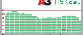
The heads installed on the front panel of the speaker are framed by two decorative overlays made of plastic and painted “metal-like” or without painting. One cover frames the midrange and tweeter heads, as well as the upper half of the front panel of the speakers, the other frames the woofer head and the lower half of the front panel. The midrange, tweeter and bass heads are protected by metal meshes. The top cover is secured with 8 screws, and the bottom with 10. The midrange head is isolated from the inside of the overall volume of the body by a plastic casing in the shape of a truncated cone. All heads are located on the front panel symmetrically relative to the vertical axis of symmetry of the speaker. At the top of the front panel there is a nameplate with the sound pressure frequency response curve and the name of the speaker depicted on it. In the upper right corner there is an indicator of speaker overload, and in the lower part of the panel there is a rectangular bass reflex output hole measuring 100x24 mm and with a tuning frequency of 37 Hz.
On the rear wall of the speaker there is a nameplate with the main technical characteristics and a block with clamps for connecting the connecting cord. The internal volume of the speaker is 27 liters. To reduce the influence of the resonances of the internal volume of the housing on the frequency response of sound pressure and the sound quality of the speaker, it is filled with a sound absorber, which is a mat of technical wool covered with gauze. The mats are located and fixed on the inner surfaces of the housing walls.
Add a link to a discussion of the article on the forum
RadioKot >Laboratory >Analog devices >
| Article tags: | Add a tag |
Radiotehnika S-50b, restoration and modification into an active speaker.
Author: Sergey Korshak Published 09.19.2010
2010
The magnificent fifties, oh, how I wanted to listen to them. I've wanted it for a long time. But I couldn't buy them. The price was too high. I couldn't afford it. Much water has passed under the bridge since then. My friends gave me an S-70, which I kept trying to perfect, changing the mid-frequency drivers and improving the ULF-50-8 tip. But I missed the novelty. I’m not a fan of listening to the same acoustics, I like it when there are a lot of them and each has its own sound, that is, its own frequency response and each acoustic is unique, but there are often coincidences. And so, having played well with the S-70, I decided to open the newspaper and look for an advertisement for the sale of the S-50b. I found a very tempting price in one of the advertisements. I decided to go and have a look. When I arrived at the place, I saw that the acoustics were in ruins. She played, but she looked miserable. Lots of scuffs and scratches + corners scratched, as if they had been hit with a hammer. I bargained and took the speakers home for 100 hryvnia (380 rubles). It turned out to be cheap according to my calculations. I brought this acoustics home and started listening. I really liked the sound. Even though there was a mid-range driver and a 20GDS, its sound was quite acceptable. There were no complaints about the tweeters. LF - the head produced pleasant soft bass. In general, good acoustics, the advisers did not lie. But her dead state depressed me, something had to be done about it. Restore, of course, as I restored the S-70 and S-30. The method here is not tricky. We take acrylic putty and begin to seal the scratched corners and dents. Of course it’s difficult with corners. Here you need to form a nice 90-degree angle, “training” the putty with a spatula. But there is a more humane way - put a little more putty on the corner and wait until it dries completely, then wrap the sandpaper in a rectangular, even block and polish until you get a nice, even corner. That's what I did during the restoration. After all the work, I covered the places where I puttyed with a thin layer of varnish, and after the varnish had dried, I wiped the entire column with a slightly damp cloth and began gluing the film. Yes, that same self-adhesive film, in the color of rare tree species, although no one forbids gluing a film the color of marble or ivory. But what came to my mind was not just the idea of restoring this speaker, but modifying it from passive acoustics to active! Like S-70. This solves all problems with space size and transportation. No one can cancel the passive connection option either, connect your amplifier for good health. In fact, the entire amplifier that will be built into the speaker consists of the end itself and the power supply. The power supply consists of a transformer and a rectifier board, on which a bank of high-capacity capacitors is also located to reduce the ripple of the rectified voltage. That's all. Now we need to decide on the amplifier. I went to wander around the “Internet” and in the depths of one forum I found an amplifier called Shushurin. A lot of people praised it for its sound quality and ease of assembly.
A symmetrical amplifier in which the pre-output stage operates in the “pseudo A” class, that is, relatively large radiators should be screwed to the outputs of the input stage. However, I was attracted to this amplifier and decided to build it. I also came across these numbers in this forum thread. “Frequency response unevenness (in the range 40 Hz - 15 kHz), dB +0.03, -0.10 Noise level, dB (A) -85.6 Harmonic distortion, % 0.0047 Output power 50 W at 4 Ohms At power close to maximum, harmonic distortion does not exceed 0.01 %" According to forum members, these indicators were measured in the Microcap simulator. The next day I already made a printed circuit board and soldered this amplifier that same evening. I installed one pair of outputs and applied voltage from a 30 volt 100 watt power supply. The amplifier started up the first time. The next step was to configure it. For those who don’t know, I’ll tell you how to properly make the first start and set up the amplifier. 1) Before turning it on for the first time, we need to make sure that the variable resistor slider for setting the quiescent current is turned to maximum resistance. Also make sure that all the transistors of the output stage, which sit on one radiator, are completely isolated from it using dielectric thermal spacers or mica, and when testing their collectors with the radiator, the multimeter showed 1 on the display, that is, infinity. Next, we need to “safely” turn on the amplifier, otherwise we were wondering if somewhere a transistor is installed with the wrong pinout. Fireworks are easy to get. So, we turn on a 220 volt light bulb into the gap between the positive and negative power supply arms of the amplifier. Turn on the power to the amplifier. If the light bulbs are bright, it means there is a problem with the installation somewhere, or maybe a defective part. If the lights do not light up or are very dim, then you should be fine. We measure the constant voltage at the output. If it does not exceed 100 millivolts, then everything is going in the right direction so far. Next you need to connect the speaker to the output. The speaker is preferably not needed, so as not to regret it later, otherwise no one is immune from force majeure. So, we connect the speaker to the output and send a signal to the input. If the signal amplifies normally, then this is good. Next, let's start setting up the amplifier 2) Let's move on to tuning the amplifier. We remove the light bulbs and connect the power directly. Let the amplifier warm up for 10-15 minutes. Then we turn on the multitester, or, more precisely, a milliammeter, into the positive gap of the amplifier power supply and begin to turn the variable resistor slider until the milliammeter shows 80 mA on the display. The quiescent current is set. Go ahead. We need to set the constant voltage at the output so that it is as close to zero as possible. To do this, we connect a millivoltmeter to the output of the amplifier and begin to turn the variable resistor motor until we find that golden mean where the constant voltage is near zero or as close as possible to it. For example, I managed to set up to 2.5 millivolts on one channel. On the second up to 4mV. 3) If you have an oscilloscope, I strongly recommend connecting a 4 or 8 Ohm load to the output; again, you may not need a speaker. (But if you have a bunch of powerful resistors, then you can connect them in series/parallel and thus create a load for testing amplifiers.) We apply a 1 kilohertz sine wave from a sinusoidal voltage generator to the input. You can use a computer sound card. We don't need super precision, we're just checking the amplifier for excitation. Next, connect the ground of the oscilloscope to the ground of the amplifier, and the probe to the output. We apply a sine and see what we have on the oscilloscope. If the oscilloscope screen shows a clean, even sine wave without steps or other nasty things, then your amplifier is ready for use. So, the amplifier is configured and ready to go. I really liked the sound of the amplifier, it sounds bright in the midrange and treble, the bass hits well. For my musical direction, ElektroHouse is what I need. As a radiator, I used a radiator from the Amphiton A1 amplifier. We tested the amplifier, it works great, now we move on to the power supply. I just had two TC-250s lying around at home, taken from old b/w TVs. Shore to build a powerful amplifier in a beautiful case, but in the end the project was frozen, and the transformers were moved to the power supply unit of the amplifier for the S-50. Why TS-250? For lack of choice. In our city, transformers are sold at such high prices that it is cheaper to buy a non-working Soviet TV from an ad in a newspaper and pull out this transformer from there, and you can also collect parts. That's what I did. I rewound the TS-250 to a voltage of 30 volts alternating. After the diode bridge and capacitors, the voltage should have been about 40 volts, that is, 30 * 1.41- (1.5 - 2) V (voltage drop across the diode bridge). At this voltage, the amplifier will deliver about 100 watts into 8 ohms, and only on one pair of 2SC5200/2SA1943 outputs. This is quite enough for the S-50b, even with a good margin.
Schematic diagram of power supply
Classic. A couple of cans to reduce ripple at the output + shunt capacitors to prevent interference. In practice, I have a 10 ampere 1000 volt diode bridge connected by thick, short copper wires and bolted to a printed circuit board. The board has 3 shoulder seats for 4700 uF x 50V capacitors. I have two per arm, according to my calculations, if you install a third, then it will only be in excess, and high-capacity capacitors for high voltage are now expensive, let’s not increase the cost of the design without a corresponding return. So now I needed to think about where I could place the structure so that it wouldn't affect the sound of the speakers, especially the bass response. The choice of place was obvious and it didn’t make me very happy, but what can you do, no one said it would be easy.
This arrangement has its drawbacks, for example, it is very difficult to fasten and assemble, but, nevertheless, I agreed to this option. So, the final amplifier with a radiator, transformer and rectifier had to be mounted on a plate, and then placed in the column through the holes of the woofer. But it didn't work out for me. The board fit through the hole, but with the electronics attached, it didn't. Then the following method was invented. The entire structure is pre-assembled outside the column. We adjust the entire layout and pre-drill holes for self-tapping screws. We check the stability of the design; after all, it will not lie in a bunker, but in a column, where very strong vibrations can create creaks and ringing from a poorly secured amplifier radiator or transformer.
After adjusting the structure outside the column, we can begin assembly. An empty board is placed in the column, then through the hole in the woofer I install all the parts and secure them with self-tapping screws in pre-drilled places. I switch blocks. Then I drag the structure, well fixed on the board, into the very front space of the column, as shown in the figure above. I tightly screw the board with the amplifier, rectifier and transformer with six long self-tapping screws. Of course, attaching the structure to the top of the speaker was very difficult. It was very difficult to stick your hands in and screw the screws to the 20 mm back wall made of chipboard. But the result exceeded all expectations. The transformer was firmly attached, not to mention the amplifier radiator and rectifier unit.
The proximity of the transformer to the amplifier does not affect its operation in any way. There is no 50 hertz background. Now let's move on to connecting the amplifier to the input and power supply, and also talk about other little things. We managed to place the amplifier in the column, we need to connect it. I drilled 4 holes on the back of the speaker, namely for attaching a switch type - button, fuse socket, input, as well as a hole for the power cord.
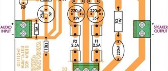
I bundled up all the wires inside the speaker, having previously secured them with insulation so that they would not dangle, everything should be in order. I also added one more little thing - I threw out the clip detector due to its uselessness, and in its place I put a red LED, which I soldered through a 5.1 kiloOhm resistor to the power supply. It's a small thing, but nice. Then I changed the location of the filter board, raised it up a little and placed it vertically relative to its previous position. I retained the ability to listen to speakers in passive mode. Well, it's all ready. Now let's move on to listening. We connect the plug to the socket and lightly press the button located on the back wall, turning on the internal amplifier. The red LED lights up, indicating that the power supply is operating. We connect the cord from the signal source to the input, which is also located on the back wall and enjoy the pleasant sound.
I listened, or rather, I’m currently listening to it while I’m writing an article, electronic music - Above & Beyond - Trance Around The World episode 337, to be precise. The sound is excellent for Soviet speakers, I can’t say anything negative, I usually listen at low and medium volumes. The appearance is impressive, if you only saw what these speakers were like when I bought them, you would gasp, it’s a pity that I didn’t take a photo, the camera was broken at that time. It is very difficult to believe that a month ago I brought these speakers killed from the outskirts of the city from some small village, where they stood in some dilapidated hut. A couple more photos taken during the creation of the project
And I congratulate our dear Cat on his anniversary and wish him prosperity, as well as more smart people on the forum!!! PS This is not the end of this article, there will be a continuation, but after the competition. The fact is that I was preparing a preamplifier for this speaker, which is based on an expensive, high-speed, two-channel op-amp - AD826, but, alas, I did not have time to finish the printed circuit board, since there was very little time left. But I promise that I will finish it soon and present it to you for your consideration. For now I can only show you a screenshot from Multisim.
Files:
Printed circuit boards in SL 5.0 format.
As usual, we put the questions here.
| What do you think of this article? | Did this device work for you? | |
| 22 | 0 | 0 |
| 0 | 0 |
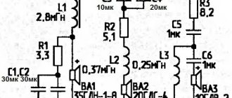
Filter S-50B
Electrical filters are mounted inside the housing on a single board, providing electrical separation of low-, mid- and high-frequency speaker bands. Crossover frequencies provided by the filters: between the bass and midrange heads - 900 Hz (±50 Hz); between the mid and high frequency heads - 5000 Hz (±500 Hz).
The design of the filters and the overload indication unit uses resistors such as BC, MLT, SPZ-386, S5-35V, capacitors such as R73-11, MBGO-2, K50-12 and inductors on plastic cast frames. The delivery set includes four plastic feet, which can be attached to the base of the case if necessary.
