Most modern subwoofer speakers are equipped with two coils. Connecting the subwoofer 2 2 is carried out in two ways, depending on which you can get different resistance. The smaller it is, the more power the amplifier will deliver.
In this article we will tell you about switching circuits and explain how serial and parallel methods differ, and also talk about the characteristics of amplifiers, since not all of them can operate stably in a low-impedance load.
We also recommend that you read the article “how to connect an amplifier for a subwoofer”, in it you will find a connection diagram and recommendations for selecting power and signal wires.
Serial and parallel connection
To connect a subwoofer speaker, use a serial or parallel connection. If the task is to connect two or more subwoofers, both serial and parallel connections can be used simultaneously.
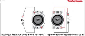
When connected in series, the rated power of the coils is multiplied by two. For example, there is a subwoofer with two 2 ohm coils. By connecting them in series, we get a resistance of 4 ohms at the output. The connection itself is made as follows: from the amplifier, “plus” is supplied to the “plus” of the first coil, and “minus” is supplied to the “minus” of the second coil. The “minus” of the first coil and the “plus” of the second coil remain unused; a jumper is installed between them. This is demonstrated more clearly in the diagram below.
When connecting subwoofer coils in parallel, the rated power will be divided by two. For example, we have a two-coil subwoofer, each coil has a resistance of 2 ohms. Using a parallel connection, we get a resistance of 1 ohm at the output. The connection is as follows: the “plus” from the amplifier is supplied to the “plus” of the first coil, then a jumper is installed that transfers the “plus” from the first coil to the second, the “minus” is connected to the “minus” of the second coil. A jumper is also installed, which transfers the “minus” from the second coil to the first. For better understanding, please refer to the parallel connection diagram below.
Do I need to switch impedance 8 ohms, 6 ohms, 4 ohms? (Which impedance should I choose?)
One of the most popular questions that an inexperienced user faces when connecting a receiver/amplifier to speaker systems is what impedance to choose on the receiver: 8 Ohm, 6 Ohm, 4 Ohm? This is especially a difficult task when the user purchases 6 Ohm speakers, but the receiver only offers 4 Ohm or 8 Ohm options. Or the speaker system data sheet indicates a range of 4-8 ohms. The desire of the owner of the equipment to understand this issue is understandable, because performance, durability will depend on this, after all, the very fact of compliance with operating rules is an important argument for warranty service. Let me make a reservation right away that I am writing this article based on many years of experience in operating and using Yamaha components, and of course, the recommendations that the user receives from the seller of a particular product should be a priority. Part of this issue has already been touched upon in the article Receiver and speaker impedance compatibility, but concerned mainly the stage of selecting components and speaker systems. To begin with, let me remind you that switching the impedance on the receiver/amplifier occurs in two ways: a) using a special switch (it is located on the rear side of the device) or b) by setting the appropriate value in the menu (usually in Yamaha receivers this is Advanced SetUp - additional , a custom menu called up by pressing a combination of buttons). In stereo amplifiers, such switching is carried out, as a rule, with a special lever on the rear side, and this lever must be switched only when it is turned off (otherwise you risk damaging the amplifier and the speakers connected to it).
Picture 1.
Amplifier rear panel.
Figure 2.
Additional menu Advanced Setup of the receiver.
First of all, the user must understand what happens inside the device when the impedance is switched. This will help you make a more correct decision and be more responsible in choosing operating modes. Switching the impedance of any amplifier or receiver changes the magnitude of the supply voltage by switching the power supply to the secondary winding of the transformer with fewer turns (switch SW101 in Fig. 3, relay RY101 in Fig. 4). So, according to the service literature, for the Yamaha A-S500 amplifier these are values of +- 78 Volts (for 8 Ohms) and 61 Volts (for 4 Ohms) AC, or +-53 Volts and 42 Volts DC, respectively, after diode rectification bridge. The need for this switching is associated with exceeding the output current maximum permissible values. As you know, according to Ohm's law: I=U/R. If the load resistance is reduced by 2 times, then the current will also increase by 2 times. If the resistance is reduced by 2 times and the supply voltage is reduced by 2 times, then the current will remain the same. A slightly different dependence of the nominal value of the output power: P=U*I=(U*U)/2R, as you can see, the power depends on the square of the voltage and if you reduce the voltage and resistance (as in the last example), then the power will drop by 2 times, in differences from the current which will remain unchanged. The question immediately arises - were the passport data for a 4 Ohm load recorded at what position of the impedance regulator? Continuing the logic, we can assume that if the rated power is 4 ohms significantly higher, then during the measurements the power supply was not switched to a smaller winding of the transformer. And one more important point - since when the load resistance is halved, the power does not increase by 2 times, this means only one thing - the capabilities of the power supply are limited to a certain limiting value.
Figure 3.
Impedance switching in the A-S500 amplifier.
Figure 4.
Impedance switching in the RX-V765, 767 receiver.
However, there are a lot of conventions in this whole theory. Firstly, the theory of calculation using direct current formulas is incorrect for a real alternating audio signal, all quantities are frequency dependent, therefore complex mathematics is required. Secondly, resistance (see the question Compatibility of the receiver and speakers in terms of resistance) also depends on frequency, and within quite wide limits, and not only should calculations take these changes into account, the main question remains - what kind of resistance does your acoustics create? real load on the amplifier/receiver? Most Yamaha speaker systems have a rated impedance of 6 ohms. This is the DC value (more precisely, it is the resistance of the voice coil of the woofer). The high-frequency capacitor of most speakers prevents direct current from flowing through the high-pass filter, leaving only the low-frequency section. As a rule, if Yamaha speakers have one woofer, then it has a DC resistance of 6 ohms, if the speaker is equipped with two woofers, then the resistance of each is 12 ohms, and their parallel connection gives the same 6 ohms. That’s all the mathematics, however, there cannot be direct current at the output of the receiver (the presence of direct current is a sign of a malfunction and it leads to the receiver turning off automatically), so these are just some guidelines in this whole house, and the real resistance of the speakers has a complex expression and is not recorded in passport. So, by switching the receiver impedance selector to 4 ohms, we automatically reduce the voltage of our power supply. It’s quite an obvious paradox - if all Yamaha speakers are 6 Ohm, then according to the instructions we must always switch to a lower voltage, the question arises: why is everything tailored to a single stamp? After all, it is absolutely obvious to me that the Soavo speakers have strong impedance minimums at some frequencies (below 4 ohms), and the Yamaha NS-555 speakers do not sag below 6 ohms, and have a comfortable impedance for most of the range. I think there is more marketing in this question, an attempt to clarify a rather complex issue, to secure some insurance...
In my opinion, the technique should be as follows: 1. It is advisable to leave the impedance of the receiver in its original (factory) position (8 ohms) - this will make it possible to receive all its electrical energy from the power supply, without reducing the dynamic range of the system, and to obtain the maximum sound quality. 2. If there are no visible reasons for switching, then leave it that way. The reasons for changing the impedance may be: auto-protection triggered due to excess current, severe overheating (usually in places where the receiver is installed with insufficient cooling). 3. There is no reason to switch to a lower impedance if your peripheral speakers (center and rear speakers) are rated at 4 Ohms. 4. It is necessary to switch to a lower impedance if: auto protection is triggered (sometimes the protection is triggered by poor-quality wire connections), if you use two pairs of front speakers (on amplifiers this is the Speaker A + B mode), if the seller or manufacturer thoroughly recommends this to you. 5. Don’t forget the main thing - operating amplification equipment in extreme modes (constant, high volume, using an equalizer, tone control at maximum values, poor cooling, poor-quality connection) can cause an overload much stronger than the impedance of the speakers.
| Return to list of questions | Go back to main page |
Which amplifiers can be connected to which resistance?
By lowering the resistance, we force the amplifier to deliver more power. For example, when connecting a speaker into 4 Ohms, the amplifier will output 500 W, and if the same speaker is reconnected to 1 Ohm, the power will be 1000 W.
The disadvantages of a low-impedance connection include:
- Increased load on the vehicle's on-board network.
- Increases amplifier distortion.
Simply put, we sacrifice sound quality in favor of volume. But not all amplifiers can be connected to a low-impedance load. As a rule, the manufacturer indicates in the instructions at what resistance the amplifier will operate stably without going into protection or breaking down.
The first thing we will pay attention to is the amplifier classes: AB and D.
- AB class amplifiers have a very low efficiency, that is, of the 100% of the power supplied to them, only 50-60% is converted into sound, the rest turns into heat. As a rule, manufacturers recommend using such amplifiers in 4 or 2 ohms. If such an amplifier is connected to 1 or 0.5 Ohm, it will get very hot. If there is protection, it will turn off itself. If it is not there, it will simply burn out.
- D-class amplifiers have an efficiency of more than 80%, as a result of which they heat up little. Such amplifiers are not afraid of low-impedance loads. The manufacturer recommends connecting them up to 1 ohm. But many people connect such amplifiers to 0.5 Ohm - here everything depends on the power supply and reliability of the amplifier.
In addition, amplifiers may differ in the number of channels. Using a two- or four-channel amplifier to connect a subwoofer, you will connect it with a bridge connection. In this mode, the device is already operating at its maximum load. If your bridged amplifier is class AB, then it can only be used into a 4 ohm load. When connected to a lower load, even 2 Ohms, it will get very hot and, possibly, go into protection, or simply burn out.
If the amplifier you want to connect is Class D, it is likely more suitable for low impedance loads and can be driven into 2 ohms. But first, you should still check in the instructions whether the manufacturer allows this.
Warning! You can connect the amplifier to a lower resistance (lower than indicated in the instructions) only if the following conditions are met: good power supply and not a maximum load. But remember that in this case the chance of equipment failure increases significantly. If something goes wrong, your warranty will be denied because you are using the device contrary to the recommendations provided by the manufacturer.
What to choose
To summarize, we can say that the speaker impedance value will not tell you anything specific and accurate about the sound quality. Manufacturers set this parameter so that impedance is taken into account when connecting the speaker and amplifier.
If the impedance is below the recommended load value of the amplifier during playback, sound distortion , or short circuit protection may come into effect; if higher than the recommended resistance, the sound will be much quieter. However, better control of the speaker sound is easier to achieve with a high parameter value and an appropriate amplifier.
So, for speakers used by music connoisseurs, where sound quality comes first, 8 Ohms are chosen. Where power is more important, the choice is made in favor of 4 Ohms.
But the most important thing is that when choosing, it is better to focus on the values indicated on the amplifier in order to correctly match the resistance, and not strive for one specific value.
Electronics and technologyComment
Switching circuits for one subwoofer to an amplifier
In this section we have collected all possible subwoofer options and variations of their connection.
Speaker with two coils 4+4 Ohm
How can I connect it?
- Using a series circuit in 8 ohms.
- Using a 2 ohm parallel circuit.
Speaker with two coils 2+2 Ohm
How can I connect it?
- Using a 4 ohm series circuit.
- Using a 1 ohm parallel circuit.
Speaker with two coils 1+1 Ohm
How can I connect it?
- Using a 2 ohm series circuit.
- Using a 0.5 ohm parallel circuit.
Switching diagrams for two subwoofers to an amplifier
In this section we have collected “almost” all possible options for connecting two subwoofers
Two speakers with two coils 4+4 Ohm
How can they be connected?
- Using a 4 ohm series circuit.
- Using a 1 ohm parallel circuit.
Two speakers with two coils 2+2 Ohm
How can they be connected?
- Using a 2 ohm series circuit.
- Using a 0.5 ohm parallel circuit.
Two speakers with two coils 1+1 Ohm
How can they be connected?
- Using a 1 ohm series circuit.
- Using a 0.25 ohm parallel circuit.