The goal of this project was to assemble a simple tube amplifier with your own hands. The main difficulties that radio amateurs who decide to assemble a tube amplifier have to face are the manufacture of transformers and housing. They were overcome by using unified TAN transformers and ready-made housings from Gainta. And although this amplifier cannot be classified as hi-end, it will be of interest to radio amateurs who decide to get involved in tube sound.
Frame
The case is the most important part of a tube amplifier, since it acts as a chassis on which transformers, lamps, capacitors, and connectors are mounted. Making a beautiful case with your own hands is quite a difficult task, so the choice fell on the use of universal cases. Thus, the basis for the chassis and casings of the transformers were aluminum alloy housings from the Taiwanese company Gainta. The advantage of these cases is good heat distribution, ease of processing, and noble appearance.
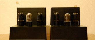
Structurally, the amplifier is made in the form of 2 monoblocks with an open design. For the chassis, B019BK housings with dimensions of 275x175x65 were chosen, on which output and power transformers, lamp sockets, and connectors are mounted. And the upper parts from B039BK housings with dimensions 171x121x106 were used as casings for transformers. The open design in combination with the aluminum housing ensures good heat dissipation from the lamps, which heat up significantly during operation.
Fig.1. Housings B019BK and B039BK - the basis of the tube amplifier chassis
To power modern tube amplifiers, kenotron voltage rectifiers are most often used. Their main advantage over semiconductor ones is the delay in the supply of anode voltage. However, this delay can also be achieved using a current source, for example, a field-effect transistor. It can also serve as an “electronic throttle” that has become popular recently. However, this device cannot fully replace a full-fledged “copper-iron” choke. Having correlated these facts, I came up with the idea of creating a tube amplifier with a not quite standard power supply. A 6N9S double triode is used as the input lamp. It gave the most natural, lively sound from a number of tubes: 6N1P, 6N2P, 6N23P, ECC83, 6N8S, 6N9S. 6N8S sounded very similar to 6N1P. The sound turned out to be slightly veiled, unclear. ECC83 is similar to 6N23P; it is not without reason that modern audio engineers, especially Western ones, love them for their soft, warm sound. 6N2P is a purely guitar tube; it is better not to use it in home audio. The most vibrant sound was achieved with the 6N9S lamp. 6P6S lamps are used in the powerful part of the amplification. For the final stage, the lamps were selected from octal 6P3S, 6P3S-E, 6P44SM, 6P6S, 6P31S. Precisely tetrodes, no triode romance. The 6P6S lamp was chosen as the most musical. This selection of tubes made it possible to create a very sensitive amplifier, which, when playing music loudly, does not forget to convey its quiet nuances, which is very valuable. When listening, we used acoustics with a resistance of 8 Ohms and a sensitivity of 91 dB (Ultimate Stage TR36). With it, the amplifier showed amazing results. The sound picture was panoramic and large-scale, despite the distance between the speakers of more than three meters. I was especially pleased with the bass; there was no need to turn it up using the tone control on the signal source. Such an audio system is completely self-sufficient even without a subwoofer. Listening to test songs confirmed this. The phase inversion stage (Fig. 1), also known as the input stage, is implemented on both triodes of the 6N9C lamp. Before the final installation of the structure, I tested two versions of bass reflexes: the above-mentioned one, as well as a bass reflex with a split load (Fig. 2). The only advantage of the latter was the ease of setup, which consisted in selecting equal values of the anode and cathode resistances. The balanced cascade is more complicated, since it requires adjustment not only for direct current (to set the operating point on the current-voltage characteristic), but also for alternating current, that is, according to the magnitude of the alternating signal on the grid of the second triode. Another important advantage of a balanced cascade is greater (compared to a cascade with a split load) gain. Although, as you know, a cascade with a split load does not provide amplification at all. However, initially only two triodes were provided for the input stage and bass reflex in the cylinder of one lamp. Therefore, the choice almost definitely fell on a balanced bass reflex.
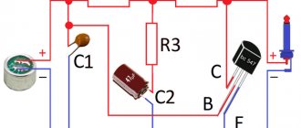
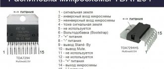
In general, tube AF amplifiers should be designed “from the end”. That is, from the output stage. Based on the value of the bias voltage, we determine the drive voltage; the driver stage and its lamp are selected for this voltage, which is usually selected from several different types according to different criteria. Some of them: internal resistance, shape of the current-voltage characteristic, shape of the cylinder, ergonomics. The lamp should be selected that is optimal not only for a given circuit, but also for a given housing. The amplifier circuit is shown in (Fig. 3). It is two-stage with a push-pull final stage. Since the final stage operates in class A, automatic biasing of powerful lamps is applied. The nominal values of the circuit elements are given in (Table 1). An RC circuit is installed in the anode load of the input triodes to improve the performance of the amplifier. There are few sources describing designs in which such a chain is used. The resistance of the resistor R is determined by the formula: R=0.12*Ra The capacitance of capacitors C3 and C4 is determined experimentally when a signal with a frequency of 1000 Hz is applied to the input of the amplifier. A rectangular signal is observed at the output of the cascade. By selecting the capacitance of capacitor C3 (C4) we achieve its best shape. The 6N9S lamp should be selected with the same parameters of both of its triodes, this is very important here. However, for other lamps of the same type the value of this capacitance will be different. Of course, no one is going to listen to a rectangular signal, but the use of such an RC chain once again speaks of how carefully the cascade is configured. The 6P6S lamp operates in the mode according to the datasheet in the mode: Ua=250 V; Ia=70 mA; Uc1= -15 V; Uc2= 250 V; Ic2=5 mA; Ra=17.5 W; Raa=10 kOm. Pout=10 W. (class A) Transferring the 6P6S tetrode with high internal resistance to triode mode does not improve the situation - in this case, the output power, even in the push-pull version, does not exceed 4 W, which is undoubtedly not enough for the desired volume level. A composite resistance of two parallel-connected resistors is used as a load for the input stage. In addition to the subjective preferences of this method of organizing the load, this method also benefits from the maximum power dissipated by the load. The device does not have a volume control. After many experiments with variable resistors, including ALPS, they did not give a satisfactory result: some, at an equal angle of rotation of the control knob, had different volumes in the amplifier channels, and most gave a noticeable effect on the sound. Therefore, it was decided to adjust the volume from the signal source - and only then did the sound of the stereo system become impeccable. The power supply in the amplifier is not quite traditionally organized: both classic, “iron” and electronic chokes are used. As can be seen from the diagram (Fig. 4), the power transformer has only one anode winding, common to both channels. In this way, smaller phase shifts between channels are obtained. How does this happen? When there is only one anode winding, then after the rectifier there is one electrolyte; if there are two anode windings, then there are respectively two electrolytic capacitors. Electrolytes, even from the same batch, most likely with different inductances. This can only be combated by averaging, introducing many capacitors; however, this approach is not justified, because fencing a box of capacitors is not entirely justified economically and energetically. Why? Well, with the money issue, I think everyone already understands. Let's look at the transformer-rectifier-capacitor-load circuit. The energy source is not a transformer with a rectifier (they only charge the capacitor), but the capacitor itself. Therefore, it does not matter which diode will be installed - fast or not. The main thing for him is to have time to charge the capacitor. Of course, this does not exclude capacitances after the voltage dividers in the power supply, but they should not be large. And there is no need to fence batteries with capacitors. Moreover, according to the recommendation of Nobu Shishido, it is electrolytic capacitors of small capacities that should be bypassed with non-polar capacitors. The second distinctive feature of the design is the use of a two-link power supply, in which, after the LC filter, two (according to the number of channels) electronic filters made on field-effect transistors are included. 2SK2996. The filter printed circuit board is shown in (Fig. 5). To maintain constant power supply to the input stage, you can use zener diodes, including vacuum ones. Structurally, the amplifier case is made in the form of a wooden box with dimensions of 220*500*80 mm. The arrangement of structural elements in it is presented in (Fig. 6). The housing is open, that is, its lamps are brought out. The power and output transformers are located on opposite sides of the housing, with lamps between them. The power supply choke is located next to the power transformer, its winding is protected by a decorative metal casing. The body material is wood, painted with automotive paint using a spray can. Each of the output transformers is placed in an individual case made of polycarbonate, treated with putty and also painted. The end result was quite beautiful covers. The space between the cover and the transformer is filled with paraffin, but it is quite acceptable to use wax. The assembly of the case and the transformer is mounted on the amplifier body using epoxy resin. At the junction of the housing and the output transformers, holes should be drilled in the housing for the conductors coming from the transformer. The winding data of the output transformer is as follows: the primary is 5100 turns of wire with a diameter of 0.2 mm with a tap from the middle. Secondary winding - 160 turns of wire with a diameter of 0.9 mm for a load of 8 Ohms. The core from the TS-80 transformer is used as a magnetic circuit. Using it, we achieve a lower playback frequency of 25 Hz (level +/-2 dB). The transformation ratio is 31. The transformer contains two identical coils. Each of them contains 3 sections of the primary and two sections of the secondary windings. Each of the primary winding sections contains 850 turns of copper wire of the appropriate diameter, each of the secondary sections consists of 40 turns. All sections of the primary and secondary windings are interconnected accordingly. Interlayer insulation is capacitor paper, no matter what they say about it. You need to wind it very tightly, since the window of the magnetic circuit is small. All secondary windings are connected in series. In general, connecting the secondary windings in series or parallel is not very good, however, this is a very separate issue. After winding the coils (still without a magnetic core), they should be boiled in wax or paraffin for 4-5 hours. Each of the output transformers is boiled in wax and enclosed in an individual polycarbonate case. Case dimensions: 130*85*110 mm. The space between the transformer and the cover is also filled with wax. No, don’t be afraid, the wax does not melt during operation of the amplifier. Irregularities at the joints of the covers are covered with putty, dried and rubbed with fine-grained sandpaper. Finished covers are spray painted. When operating even at full output power, the transformers are silent, as they should be. Choke L1 contains two identical windings. It is wound on a magnetic core made of W-shaped plates measuring 70*80 mm. The thickness of the set is 20 mm. A rewound television TSSh-170 was used as a power transformer. The voltages of its secondary windings are indicated on the power supply diagram (Fig. 4). The maximum output power of the amplifier is 10 W, but I took the characteristics at an output signal level that is typical for operation in cases of 8 and 4 Ohm loads, respectively. The measurement data after an hour's warm-up of the amplifier are given for a 4 Ohm load (Table 2), and the frequency response graphs are shown respectively in (Fig. 7). The frequency response in the low-frequency region is separately presented in (Fig. 8). Setting up the amplifier consists of balancing the bass reflex. By adjusting the variable resistor R11, equality of the alternating voltages at the anodes of the triodes is achieved with an alternating signal at the amplifier input. Next, a rectangular signal is supplied to the input and by selecting, or better yet, by smoothly adjusting a variable capacitor, the best rectangular shape is achieved at the cascade output. Then the final stage is configured. It is very important not to saturate the output transformer, but since this stage is push-pull, we need to set equal currents in each arm. In the design I used unmatched pairs of 6P6S lamps, which did not prevent me from obtaining excellent results. By adjusting resistors R14 and R15 we achieve equal anode currents. It’s good if their size is at least somewhat similar to the values indicated in the datasheet. The feedback resistor R* is variable, its resistance can be selected to suit your taste in the range from 2.7 to 4.7 kOhm. By adjusting it we achieve the most stable operation at maximum bass volume. A few words about the kit. Cathode polar capacitors are from the manufacturers Rubycon and Jamicon, non-polar capacitors in the power supply are domestic, brands K73-17, K73-16, capacitor C7 and C9 in FI are brands K42U-2, C8 and C10 are brands KSO. These capacitors, despite their great age, behave very neutrally, and their shunting of interstage capacitors of larger capacities has a beneficial effect on the sound. Wima capacitors, praised on forums, did not show the best results. Anode resistors are carbon, grade C2-23-1, the rest are MLT or OMLT. It is very useful to match all lamps in pairs based on equal quiescent current at the operating point, or at least take samples of the same production date from the same batch. The power and output transformers are located as far as possible from each other. The lamp sockets are mounted in a U-shaped structure made of foil PCB. The output terminals are located behind the output transformers, the length of the wires between the terminals and transformers is minimal. There are only 6 terminals for connecting acoustics with a resistance of 4 and 8 Ohms. Substitutions that are better not to make. An analogue of the 6P6S lamp is the imported 6V6, and the 6N9S lamp, with some reservations, can be replaced with a 6N2P or ECC83 finger-type lamp, although any replacement will have an adverse effect on the sound, since, for example, the 6N2P lamp is only similar to the 6N9S in terms of current-voltage characteristics and internal characteristics, but the sound is significant the differences are noticeable.
Author: Andrey Timoshenko https://www.heavil.ru
You may be interested in:
| Radio tubes used in the article:
|
Comments on articles on the site are temporarily disabled due to a huge amount of spam.
Advertising:
Throat spray at a bargain price here. — entrance and registration to Bui
Transformers
The main element of a tube amplifier is the output transformer. Since the complexity of manufacturing transformers is an obstacle not only for beginners, but also for many experienced radio amateurs, the choice was made in favor of using ready-made transformers. But specially designed and wound output transformers are usually very expensive. An interesting alternative solution was proposed by S. Komarov in a series of articles in the Radio magazine - to use unified TAN transformers as output ones. The main advantage of this option is the price, which is an order of magnitude lower than audio output transformers. This was the main factor in favor of using TAN transformers.
For this amplifier, TAN3-127/220-50 transformers, available at that time, were selected. Instead of these transformers, it is quite possible to use TAN13, TAN14, TAN15, as well as TAN27, TAN28 TAN29. To use TAN transformers as outputs, it is necessary to take into account that the network winding of the transformer had to be separate, with a 127 volt outlet (the transformer is marked as 127/220).
TAN3 were also used as power transformers. By connecting the secondary windings in series at the output of the transformer, we obtain the required voltage.
Fig.2. Transformer TAN3-127/220-50
Ultra linear amplifier
However, in two-stroke use they also did not disappoint. The scheme published below has had many incarnations. The ultralinear version, for example, was in the very first edition of Gendin’s book “High-quality amateur ULF” (1968).
Output power = 12 W (Kg<0.5%).
By the way, about the ultra-linear switching of the output pentodes. In the push-pull version, they have another advantage - additional compensation for harmonics arising in the output stage. Therefore, the vast majority of amateur designs are made according to the ultralinear version.
In domestic industrial designs, ultralinear amplifiers again did not take root due to the complexity of the output transformer.
To obtain high performance, complete symmetry of the design, sectioning of windings, and complex switching are required. When using mass-produced transformers, the benefit from using an ultralinear circuit is invisible.
The following design has become a classic and has served as the basis for countless designs.
Rice. 4. Schematic diagram of a push-pull ultralinear tube amplifier based on triode pentodes (6N2P, 6P14P, 12 Watt).
The output transformer is made on a Ш-19×30mm core. The primary winding contains 2x(860+1140) turns of wire d=0.18. The secondary winding (15 Ohm) contains 176 turns d=0.83. For a 4 Ohm load - 90 turns d=1.3mm.
The circuit practically does not need to be adjusted, which has earned it popularity in industrial and amateur designs. The bass reflex is designed according to a load-sharing circuit.
Amplifier circuit
The amplifier is built according to a classical circuit, consisting of two stages: a bass reflex on a V1 lamp and a push-pull output stage on 6P6S pentodes (connected by triodes) V2 and V3. The phase inverter is built according to a balanced cascade circuit, characterized by a high gain and symmetrical signal separation.
Fig.3. Circuit of the Epifit tube amplifier using 6P6S and 6N9S tubes
Fig.4. Circuit of the Epifit tube amplifier using 6P6S and 6N8S tubes
Push-pull stereo tube amplifier.
Sergey Nikitin
This article is a continuation of the started topic about tube amplifiers, where we looked at the manufacture of a stereo SE amplifier using EL34 (6P3S) or KT88 tubes. In this final part of my story, we will try to assemble together with you a push-pull (PP) stereo amplifier using KT88 tubes. But first, as always, let me remind you of the safety rules:
ATTENTION!!!!
Before manufacturing or even prototyping a tube amplifier, it is necessary to study the “Electrical Safety Rules”, because in tube amplifiers the operating voltages are several times higher than the voltage in your electrical network; the circuits contain storage capacitors that can retain a powerful charge for a long time that can kill a person.
As in the previous article, personal feelings in the perception of sound will be described here, some points that I encountered in the process of work, errors, etc.
And now everything in order, about how it started for me. I’ll tell you a little background of my work, I’ll try to keep it short so that you don’t get too bored. Usually people start designing something easier, simpler, but for some reason it doesn’t work for me. And I immediately began to make not a simple single-stroke, but a two-stroke, and, as always, from what was available or could be found almost for free. I found suitable hardware, in my opinion, some kind of transformer from a power supply, but not Chinese that’s for sure, with a power of about 30-20 W. I started to figure out what it could be good for - and it turned out that the anode winding only accommodates a 0.1mm wire. When I wound it, I decided for myself - I don’t wind it with this kind of wire anymore, it’s better to have a larger transformer than necessary (the reserve, as they say, is not enough), but winding it with a thin wire is very difficult, and then there’s the sound “pie”. This was my first layout that I liked and where it all started. The speakers on which I listened to my creation were 25AC-126, which had to be redone because the very loud midrange hurt my ears. Approximately the same effect is observed in the S-90. I already wrote about the conversion of the 25AC-126 on this site.
The next amplifier was already made as a complete and complete design, and immediately on the 6R3S-1, because I already had them in stock from the TU-100 that I inherited, this is an old tube amplifier, by the way, it has a decent power transformer and good audio hardware . After rummaging through the caches I found his photo and data on sound transformers. In this amplifier, output transformers with a short core (35mm) and a huge window (winding height 25mm) were used; in the photo below behind the lamp you can see that they are not standard.
1440 turns were wound on each anode and the output winding was 116 turns. I don't remember the diameters of the wires. As you can see in the photo there is both a balance control and a tone control. But later, it turned out that apart from the volume control, nothing was needed; the rejection of unnecessary bells and whistles also saved an extra stage. The anode voltage was 350V, the bass reflex was 6N2P. This one stage was enough to drive the 6P3S-1; the sensitivity was actually about 1V. It is not convenient to measure the anode current of the 6P3S-1, they have a common cathode, and I had to go crazy measuring the voltage drop across the transformer with a known resistance of its windings. I measured very carefully, because high voltage and long ends of the measuring wires are trying in every possible way to drive the cascade into self-excitation. The appearance of this amplifier is certainly not very good, I didn’t even try, since I needed to “bundle” it faster, and this is what “it” turned out to be.
The next amplifier was already a 6P1P, and also from what was found in the bins. I tried 6P14P there, I didn’t like their sound, it was very retro, and the 6P14P tube with external bias quickly goes into self-heating.
Here he is in the photo, with 6P1P. It didn’t sound bad at all, and still does in Moscow, but its power wasn’t enough for me and I returned to the 6P3S again.
And this happened. Monster.
But I very quickly stopped liking its appearance, and I “charged” to build an amplifier even more powerful, trying to squeeze 100W out of 6P3S tubes.
And I got this.
But I was disappointed in this design - the parallel connected lamp anodes made the sound terrible. I already had GU-50s in stock in quantities that allowed me to spoil them a little, and the panels for them are the same as for the 6P3S. I decided to try to build an amplifier using them.
And this is what happened.
The sound, of course, was not as velvety as in the very first case with the 6P3S-1 (one tube per channel), but it was quite good. It was only 540 volts of the anode voltage, it is not pleasant to take measurements there at such a voltage. This design worked for me from 2010 to 2015.
In parallel with this amplifier, I also made this version for 6P3C, for myself and for pleasure, because, well, I really liked the sound of them (6P3C).
But I didn't enjoy it for long. Once a friend brought his friend to visit me, and he liked him even more than me and the amplifier left with him...
Then there were experiments with 6P3S and kenotrons. A very successful design, it’s a pity that we had to put four diodes in the bias rectifier of the output lamps, otherwise everything would have been on lamps.
There are even electrolytes and old Soviet TVs and resistors, mostly for aircraft, that work.
As I already said, every design is an experiment. I now have 6C41C lamps (powerful triodes), and even large dial indicators have been lying idle for a long time, and on top of that, I haven’t heard the lamps in triode mode yet (I haven’t assembled them) and again a new design has appeared.
I really liked the sound, the driver had 6N6P, I tried to install 6N23P (they have the same pinout and do not go beyond the specifications), it turned out that with 6N23P the sound is much softer.
It was on this design that I ran into these yellow capacitors (they were mentioned in the previous article), which ruined the sound. Now I know it's bad. The capacitors were later replaced.
But I will say - the 6C41C is a “heavy” lamp, with a high filament current, with a high cut-off voltage of about 140 Volts, it takes a very long time to warm up and while it’s warming up and even working, it crackles all the time (the main thing is that it’s not in the speakers). It cools down and crackles again. The panels for it need very good, ceramic ones. In order not to heat the cathode resistor (and there is about 140 volts and at a current of 0.07A) and not to make the anode supply voltage very high (minus these 140 volts, which are lost on the cathode resistor), I made an amplifier with external bias. But then the lamp became unstable and began to self-heat. I had to combine. About 30 Volts of auto bias, the rest is forced. Then it started working perfectly, although it’s no longer for me. Pointer indicators were used to control the output power, and most importantly, they could be used to control the anode (cathode) current of the output tubes. This amplifier pulled out about 30W.
I’ve probably already tired you, sorry, now let’s return to the described structure, which we will assemble. Initially, in all my designs of push-pull amplifiers, I used this classic bass reflex circuit.
A very worthy circuit, oddly enough, amplifiers were pumped up to 54 kHz with it. The 6N2P produced a higher gain and a softer sound. 6N1P sounded more detailed, it sounds similar to 6N8S.
As you can see in the photo from 2016, the appearance of our amplifier has changed a little. During the creative process, the top panel was sawn and cut to fit different lamps and panels, so I had to make decorative overlays like this on top to close the holes that formed there.
Now for the diagram and details. The input stage is made on 6N9S, it sounds a little softer than 6N8S, but if you want detail, then 6N8S is better. They can be changed for testing without changing the circuit, but for them to work correctly, you need to change the operating mode of the lamp.
The 6N9S has a high output impedance, so it’s difficult to drive the output stage without blocking the frequency response, but you can try.
WARNING: Never remove tubes while the amplifier is on, even the input stages. You can insert a cold lamp. Otherwise, breakdown and failure of the output lamp is guaranteed.
The bass reflex is made on the 6N8S according to a different design, to “punch through” a larger input capacitance of the output stages, and it seems to work more symmetrically. It didn’t add any softness to the sound, but it didn’t seem to spoil anything. Before that, there were 6С5С (1960 release, new), as in the photo, but one burned out, I didn’t want to go to the store again, and 6Н8С is still in stock, so I slightly changed the wiring on the lamp socket and put 6Н8С there. True, one triode was left out of use, but I did not parallelize it, I don’t have very good impressions of this.
The output stage is made on KT88, they are now expensive, about 70 USD apiece, so be careful with them.
I tried them in triode mode, I didn’t like them (the amplifier was charged with a triode and a pentode, there was even a switch left), I didn’t like the pentode connection recommended in the reference books (this is when the second grid is connected to the power supply of the anode circuits) I didn’t like it either, the sound was harsh. Therefore, by slowly reducing the voltage on the second grid while maintaining the anode current at about 80 mA, I reached the following parameters for resistor R23. The anode current is measured by measuring the voltage drop across the cathode resistors R32-R33 (within 0.8-0.9V). The main thing is that the currents in the channel are as equal as possible, otherwise there will be a slight problem with the sound and the main disadvantage is the background in the speakers. I ordered the selected four KT88s, so after they are broken in, they no longer “float away” anywhere.
In this circuit, there is a delay in the supply of high voltage to relays P1-P2, they are 24V from the UPS-1200 uninterruptible power supply. For a smoother start, use NTC R26-R27 16 Ohm thermistors; you don’t have to install them at all, or you can use 25 Ohm ones. When connected to the network, the capacitors of the power supply begin to smoothly charge through resistors R24 and R25, and capacitor C33 is also charged through resistor R36. Upon reaching the breakdown voltage of the neon light bulb HL1, the lamp breaks through, capacitor C33 is discharged through the control electrode of the thyristor, it opens, turns on relays P1-P2, which with their contacts bypass resistors R24 and R25, and discharge the timing capacitor C33 to prepare it for subsequent switching on. I got a delay time of about a minute. Why a neon light bulb and not a dinistor? It does not produce leakage current, so capacitor C33 can be installed with a small capacity (just not the electrolyte!!!) with a high resistance of the time-setting resistor R36, and I have a lot of these neon capacitors, so I found a use for them. I even installed neon lights from a starter on 127V fluorescent lamps in “field” conditions, and they still work, but in a different design.
In rectifier bridges, you need to use fast diodes (they produce less interference) at the appropriate voltage. You can install KD226, used in 3USTST TVs and the like, you can also use imported Schottkys, but keep in mind that Schottkys are very afraid of the slightest overvoltage, so they need to be taken with a reserve of reverse voltage (at least two supply voltages). I didn’t draw it in the diagram here, but it is advisable to bypass each diode in the bridge with a capacitor of about 0.022-0.01 μF 400V. This is all to suppress interference. Resistors R46 and R35 are needed to reduce inrush currents. Thanks to all these bells and whistles, I have never blown fuses (they are installed on circuit boards in the basement of the chassis), so I don’t need to think about the convenience of replacing them.
One standard D25 is used as chokes (also found in the bins), the other is unknown, wound with 0.4 mm wire, inductance about 1 Henry, from some kind of equipment. You can wind it yourself, on suitable hardware, and don’t forget about electrical insulation, it’s already 460 Volts!!
Interstage capacitors need to be installed as I wrote earlier from these.
By the way, for an experiment in powering the second grid of the output lamp, I bypassed the electrolytes with yellow capacitors. Did not like. Replaced with old CBG. Got better. Here in the photo is a view of his “giblets”. Between the input stage and the bass reflex there are 0.1 uF 200V capacitors, these are very old Soviet ones, and I think that they will work for another 100 years. Don't be afraid of old parts, they are more reliable than modern ones. The only thing you can't guess with electrolytes, although they also work.
Now again about the most important and tedious thing, these are the output transformers.
At first I had transformers of lower power here, but then I decided to rewind from what I had. And there was a pair of TSSh-170, these are from tube TVs, not so great, the iron is a bit thick, at the limit. To calculate the weekend, I took data from other sources, I didn’t calculate it myself, but I added a few turns in the primary. It turned out in real life, and then I recalculated it using my own method, it turned out that I added very little, below 30 Hz the signal is noticeably distorted, it does not hurt the ear, but the fact remains a fact. And so this has already been done, half (for one anode) 800 turns, plus the second anode 800 turns, the secondary 64 turns, 800 + 800 = 1600 and divide by 64 turns we get 25, coefficient. transformation, square it, we get 625. Since this transformer was originally made with an output resistance of 5000 Ohms, then 5000/625 = 8 Ohms, this is the load resistance that is needed. But…. here now there are KT88 lamps with an output impedance of 3500 ohms, therefore for this situation a 4-6 ohm load will not be critical.
I repeat once again, I don’t like these transformers, so I will replace them in the future project. For now I’m thinking about OSM-0.25, but maybe I’ll come across something else that’s suitable. For me, the anode winding should be about 1200 turns each (1200+1200) on TSSh-170, and the secondary should be considered for the specific resistance of the speakers. TSSh-170 itself is large, and the window is not enough, so you need to estimate everything more accurately so that all the windings fit in without problems.
The primary (anode) winding was wound with a 0.25 mm wire, and the output winding was 0.51 mm.
The winding proceeded in the following sequence: - output winding - half of the first anode - output winding - half of the second anode - output winding - half of the second anode - output winding - half of the first anode - output winding.
Why is that? This is done to equalize the active resistance of the windings of the two anodes. The first winding has the smallest resistance, and the last winding has the largest, with the same number of turns (the winding diameter is larger). In this situation, they turn out almost perfect.
Now we soak, dry, and spill. Everything is as it was in a single-ended amplifier. We check the frequency response of transformers, here you will measure the real frequency response of transformers, because there is no core bias here, unless, of course, both anodes operate with the same current.
Now the power one.
The power one was originally from the TU-100, only the filament windings were rewound, but it has paper cheeks, and due to old age, after the second breakdown between the petals on these cheeks, it was decided to replace it. Yes, the transformer is powerful. I didn’t have to search for long, since there was still waste, and the old faulty UPS-1200 UPS came in handy here. The first transformer was wound, the current X.H. was initially checked. at a voltage of 220V, 180mA, it seems a bit too much, but I wound up a power supply, installed it…. and horror, when turned on, the magnetic screens (between the power and sound) clapped against it (they became magnetized), and even the background in the speakers... In short, I had to throw it away, because it was already flooded and soaked, and I fill it so much that it can’t be taken apart again.
I took a UPS-1200 from another, a different company, it has the current H.H. at 220 Volts it was 38mA, I wound it like this:
First, we apply 220 volts to it and measure the output voltage on its output (low-voltage) winding. Then we disassemble, wind up and count the turns (we wind up to the network winding), divide their number by the measured voltage on this winding, I got exactly 2 turns per volt.
The total current of all anodes for which I calculate this amplifier is 0.5A, so the wire also turned out to be 0.51mm and I have plenty of it. Because the anode voltage is high (460 Volts, and electrolytes have a maximum of 450 Volts in nature), we will receive it from two sources connected in series, therefore we need two windings. We consider 460/1.4 = 326 Volts / 2 windings = 163 volts, but this is without load, add 17 volts for roundness and get 180 Volts of alternation each anode winding should produce.
To bias the lamps themselves, we need about 40 Volts, but just in case and for a drop in the filter resistors and the reserve, let there be about 100 Volts, therefore 100/1.41 = about 70 volts of alternating time. The current there will not be large, a few milliamps, so this ratio will be close to the truth. Now, what kind of wire to wind, I had 0.35 mm, plenty of it and not thin and not thick. I'll stop there.
To power the relay you need 24-28 volts, so without doing any calculations, I already know that 20 volt alternations will be enough. What is the diameter of the wire? Relays take up to 200mA, plus an LED, plus maybe something else, after some calculations there is enough space, and I think 0.51mm is also enough.
Now specifically on the turns.
W1-W2 – network ready.
W3-W4 - 360 turns of PEV 0.51 wire each, they have taps at the 300th turn for the versatility of the transformer. I didn't show this on the diagram.
W5 - 140 turns of 0.35 mm wire.
W6 - 40 turns of wire 0.51 mm.
W7-W8 - 13 turns of 1.7mm wire, which, by the way, was wound from the same transformer. These windings were wound with a tap from 11 turns, this is 5V for heating two kenotrons, and also for the versatility of the transformer, and two more windings of 13 turns with 1.7 mm wire fit in, this is 6.3V purely for incandescence. I’m trying to make the transformer more universal, because you start making one amplifier, and while you’re making it, then during the work you suddenly need to change the voltage or something else, but with a universal transformer you can try all this.
Don’t forget to insulate well between the windings, especially where the winding is for the kenotron and its heat. Between other windings, two or three layers of insulation are enough. Inside one winding, we insulate the rows with one layer of insulation, this is enough.
Soak, dry, spill. Don’t forget that after the first impregnation the plates will need to be tightened, since our varnish will dissolve the old one and they will fit more tightly, maybe even the remaining “extra” plates will fit in.
The body here was made of plywood, but apparently you need high-quality plywood; during this time it burst a little.
As you can see in all the photos, the placement of the transformers is the same and the type of amplifiers is also almost the same. This is due to the fact that I have not found another more compact arrangement of transformers so that the power transformers provide a minimum of interference to the audio outputs. Before installing transformers, you need to find the optimal position in which there is a minimum of noise in the speakers. I already talked about this in a previous article about single-ended amplifiers.
For the convenience of monitoring anode currents, I have small sockets from old Soviet equipment on the top panel at the back, opposite each output lamp. There are also resistors for adjusting the anode current and current symmetry. It’s more convenient for me, I set the current of each lamp, and then you connect a multimeter (and I have one like this, since 1978 it has served me faithfully), between the cathodes and set the symmetry to “Zero”.
The first turn on of the amplifier must be done through LATR. In general, I do the very first switch-on without the anode power supply, checking the filament voltage, lamp turn-off voltage, and other auxiliary power supplies. Then I set the maximum blocking voltage on the lamp grids (the slider of resistor R21 to the very top of the diagram), and the slider of resistor R18 “symmetry” to the middle position, and after that I just turn it on with the anode voltage. When you turn it on for the first time with LATR!!!! it is necessary to bridge the anode-cathode of the thyristor in the high-voltage delay circuit, or the corresponding relay contacts K1.1-K1.2, gradually increasing the supply voltage, measure the anode supply and the anode current, so that it does not accidentally “run away” beyond the limits for some reason. We make sure that nothing smokes or explodes. After reaching the nominal supply voltage, we begin to reduce the blocking voltage and look at the anode current of both lamps, you can take turns, but be sure to look at both. When one of the currents reaches the nominal mode, we use a “symmetry” resistor to adjust the second to the first. And so on until we set approximately the same modes. Then we do the same with the next channel. And again we return to where we started. This operation will need to be repeated several times, because with the appearance of a load on the anode supply, it will sag and the already set anode currents will decrease. Added to this is the running-in of the lamps, especially the first hour of operation. The final “finishing” adjustment should be carried out no earlier than after 1-1.5 hours of operation. But then it will be necessary to periodically monitor the anode currents, this is the first few days of operation, then this will need to be done no more than once a month or less.
What I would like to say in conclusion is that this is not the final design yet. There is a desire to remake it, try other options and details. But what kind of acoustics you have is also very important. I started with 25AC-126, it was modified more than once, the final version is described here. The result was a most magical sound, it’s just fantastic, I could sit for half a day and listen to this sound, it’s very difficult to convey emotions. I really liked listening to “Relax FM” through a satellite receiver (by the way, you can see it in the photos), I chose one of probably twenty brands by sound, there was such an opportunity to choose. But having moved to another apartment, the previous one had a square room 4.2x4.2, this velvety sound was no longer there. But the most interesting thing is that in the new apartment he was still working with the construction finishing (while the renovation was going on) and it sounded like nothing, but... after puttingtying the walls everything changed dramatically for the very worse. It got a little better after wallpapering the walls and filling the room with furniture, but it’s not at all the same as it was in the old apartment. And even the new 80-liter full-fledged floor-standing speakers, made almost according to Feng Shui, did not return that sound. The room is almost the same in size, only rectangular. This is what happens with sound. I really want to hear exactly that sound, where there were moments when animal fear and a thrill from the sound crept through the infra-low frequencies.
Good luck.
power unit
The amplifier's power supply is assembled according to a classic transformer circuit with a bridge rectifier and an LC filter. TAN3 was used as a power transformer, all of whose secondary windings (except the filament windings) are connected in series to obtain an anode voltage of 300 volts. To increase the load capacity, the filament windings are connected in parallel. To reduce the background level, an artificial midpoint was created from resistors R15 and R16. The LC filter uses standardized D21N chokes with an inductance of 2.5 H and rated for a current of 0.14 A. The inductor windings are connected in series.
Most of the parts (circled with a dotted line) of the power supply are assembled on a printed circuit board, which is inserted into slots provided in the chassis. A photo of the assembled power supply board is shown below.
Fig.5. Assembled amplifier power supply board
Simple push-pull amplifier
Output power = 6 W.
The output stage is designed according to a cathode-coupled circuit. The reduced load resistance is 8 kOhm. The design details of the transformer are unknown.
The power supply uses a full-wave rectifier based on a 5Y3GT directly heated kenotron and an LC filter.
Rice. 1. Schematic diagram of a push-pull amplifier on 6C4, EL84 (6 Watt).
It is interesting to include a volume control at the input of the final stage and only one transition capacitor. The degree of cathode coupling is low, so the sound character will most likely be like that of a single-ended circuit (with even harmonics). There is no general OOS, since the gain margin is small.
However, the introduction of OOS into a pentode amplifier is highly desirable - without it, the output impedance is very high. This is good only for the midrange band (because it reduces intermodulation distortion in the dynamics), and is contraindicated for all other applications. Deep OOS can be introduced into an amplifier only with direct connection of cascades.
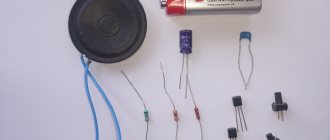
Parts List
The table below presents a list of parts required to assemble one monoblock tube amplifier. For the stereo version you will need 2 times more details.
| № | Name | Quantity |
| 1 | Lamp 6P6S | 2 |
| 2 | Lamp 6N8S | 1 |
| 3 | Lamp panel PL8-2P | 3 |
| 4 | Transformer TAN3-127/220-50 | 2 |
| 5 | Throttle D21N | 1 |
| 6 | Capacitor K71-7 0.5 µF | 4 |
| 7 | Capacitor 100 uF x 400V | 3 |
| 8 | Capacitor 100 uF x 25V | 1 |
| 9 | Resistor 39 kOhm 0.5 W | 2 |
| 10 | Resistor 270 kOhm 0.5 W | 2 |
| 11 | Resistor 430 Ohm 0.5 W | 1 |
| 12 | Resistor 3.9 kOhm 0.5 W | 1 |
| 13 | Resistor 470 kOhm 0.5 W | 2 |
| 14 | Resistor 1 kOhm 0.5 W | 2 |
| 15 | Resistor 200 Ohm 2 W | 2 |
| 16 | Resistor 220 Ohm 2 W | 1 |
| 17 | Resistor 2.2 kOhm 0.5 W | 1 |
| 18 | Resistor 200 Ohm 0.5 W | 2 |
| 19 | Diode bridge RS206 | 1 |
| 20 | Tumblr | 1 |
| 21 | Fuse holder | 1 |
| 22 | Fuse 0.5 A | 1 |
| 23 | Network Europlug | 1 |
| 24 | RCA connector | 1 |
| 25 | Speaker jack | 2 |
| 26 | Aluminum housing Gainta B019BK | 1 |
| 27 | Aluminum housing Gainta B039BK | 1 |
| 27 | Instrument leg | 4 |
Scheme 2. Push-pull almost “triode” ULF on 6P3S, 6P3S-E (6L6 G, 5881)
Typical output stage lamp mode (from the reference book): Ea = 360 V, Eg2 = 270 V, Eg1 = minus 22.5 V, Raa = 6.6 KOhm, Ia = 2 x 44 mA, Ig2 = 2 x 2.5 mA , At Uin = 0. Ia = 2 x 66 mA, Ig2 = 2 x 7.5 mA, At Uin = 45 V amp. P = 26.5 W, Kni = 2%.
No recommendation was found in the datasheet for this lamp for the percentage of screen grid voltage for ultra-linear turn-on. Therefore, by a strong-willed decision, based on the developer’s own experience, the value of 33% was adopted. However, one must understand that ultralinear switching significantly reduces the output power of the amplifier relative to the given reference data for “pure” push-pull amplification in class AB mode. This occurs due to the fact that when the lamp is opened, with a positive half-wave of the input voltage, not only the anode (output) voltage decreases, but also the screen grid voltage, which leads to a decrease in the amplitude of the anode current, relative to the value to which the lamp could open when constant voltage of the screen grid. Due to the introduction of ultralinear feedback, the characteristics of the output stage lamp are close to those of triodes. By smoothly changing the percentage of alternating voltage on the screen grid, for example, using a potentiometer, you can establish the optimal ratio between the maximum output power and the “triode” sound. But it is better for each radio amateur to do this individually to his own taste. Of course, the 26.5 watts given in the reference data at an alternating voltage on the screen grid of 33 percent of the anode cannot be obtained, but the amplifier will sound especially gentle.
Having carried out similar calculations as for the previous circuit, we find: Uaa = 592 V, Ua = 296 V, Ua eff = 210 V.
Based on the above calculations, we also note that we can get an output power of 26.5 W from the TAN transformer only at a 4 Ohm load. We will rely on this for our amplifier. The required transformation ratio for a resistance ratio of 6600 to 4 is 40.6.
Since the voltage across a 4 Ohm load with an output power of 26.5 W should be 10.3 V, we can use taps of filament windings when accurately selecting the required turns ratio. We are satisfied with the following switching options: 5 + 5 = 10 V (with a slight overload of 0.3 V), 5 + 5 + 1.3 = 11.3 V and full switching: 5 + 5 + 1.3 + 1.3 = 12.6 V.
So, we need to select a transformer that has a double set of windings with voltages in two combinations: 110 + 100 and 127 + 83. In a real selected transformer, these voltages may be a little higher, but in no case less! And at the same time, so that there is one more (a pair, of course) winding to power the screen grid with a voltage of 210 / 3 = 70 V.
As mentioned earlier, the power of the selected transformer should be around 100 W. However, it is of interest to use for this circuit slightly more powerful transformers with a rod core and an arrangement of windings on two symmetrical coils. This is a series of transformers from TAN69 to TAN82 with a power of 122 W.
According to the calculated initial data, we are satisfied with two transformers: TAN72-127/220-50, a combination of windings 127 + 80 + 24 (anode) and 56 - screen; TAN73-127/220-50, - combination of windings 127 + 80 + 20 (anode) and 80 - screen;
In this case, the “ultralinear” screen winding of the TAN72 will be 24% of the anode winding, and of the TAN73 - 35%. The connection circuits for both transformers are the same.
At the same time, in order to maintain the required transformation ratio as accurately as possible, the load must be connected to the output filament windings connected to a voltage of 11.3 V (5 + 1.3 + 5). In this case, the transformation coefficient will be: for TAN72 coefficient: 2 x (127 + 80 + 24) / 11.3 = 40.9 and at the same time Raa = 6686 Ohm. for TAN73 coefficient: 2 x (127 + 80 + 20) / 11.3 = 40.2 and at the same time Raa = 6457 Ohm.
The presence of both transformers (and they are very inexpensive) opens up the possibility of experimenting with the magnitude of the alternating voltage on the screen grid.
The beginning of the primary (mains) winding must be included in the anode circuit of the lamp. This pin has the minimum capacitance for the remaining windings. Then, sections of the anode windings are turned on sequentially in increasing order of their terminal numbering. This inclusion of the windings allows you to obtain the maximum bandwidth of the transformer, which, in general, is not intended for use as an output. From the same considerations, the inclusion of the windings of the output transformer in circuit 1 was chosen, taking into account the specifics of their placement on the armored core.
This circuit uses a combined bias to the control grids of the output stage lamps. Automatic biasing due to the common current of both lamps provides 40% of the bias voltage, and the remaining 60% is set from a separate rectifier and balancing circuit.
The only difference between the preliminary stage and the previous circuit is that the phase inverter with a split load is powered by a higher anode voltage to ensure good linearity of amplification with a significant swing (double amplitude) of paraphase voltages (two times 45 volts).
The first switching on and adjustment of the amplifier are completely identical to the previous circuit. The rectifiers are assembled according to classic full-wave circuits and do not need any explanation.
The sensitivity of the amplifier at a frequency of 1 KHz at maximum output power is 0.775 volts effective value. And the bandwidth with an average output power of 8.5 W from 24 Hz to 24 KHz over the blockages is minus 3 dB.
The amplifier assembled by the author with the TAN73 transformer showed excellent sound with very rich low frequencies, a hard “middle” and very gentle and transparent high frequencies. In this circuit, not only 6P3S and 6P3S-E lamps were tested, but also 6F6S, EL34 and 6550.
The most “delicious” and pleasant sound was provided by 6F6S output tubes, however, with a load of 8 Ohms and the output windings being fully turned on.
Here is a brief emotional description of the sound of an amplifier with different tubes: 6P3S-E - The sound is elastic, as if slightly compressed, powerful lows, and very clear highs. But this sound is oppressive and you won’t listen to it for a long time. It sounds just like guitar amps! This is an analogue of the American 5881, which is exactly what is used in these combos. She has an electric guitar sound. It is still not quite 6L6, which is almost an exact analogue of our 6P3S. 6P3S - Transparent natural sound with very good separation and audibility of both quiet and powerful sounds. All overtones and different instruments are clearly audible. 6F6S - Very interesting sound. You can listen all day long without getting tired. Everything is very transparent, gentle and musical! 6550 - Strong powerful sound. Solid, one might say. The lows sound, as my brother puts it, “your fur coat is wrapping up”! EL34 - Deep powerful lows, very gentle highs and hard mids. The voice sounds very harsh. However, the piano sounds tenderly. 6P6S - no way. It's dead and tasteless. It is not suitable for this amplifier. A bit weak.
And I also saw the difference in sound that the pre-tube makes. 6N8S - ours, classic, gives a slightly smeared soft sound. 6Н8С-6SN7 from RFT 1954. There were some with a double name, they give a very hard and clear sound - as if it was written according to the rules! And the tops become like steel! 6Н9С - when combined with EL34 it gives a rather interesting sound with emphasis on the high frequencies. The brushes are very emphasized. However, the lows sound relatively colorless. And in the kit with 6P3S there was no sound at all... so, something incomprehensible and “nothing”. 6550 and EL34 tubes are too powerful for this amp. You can install them and they work fine, but they require higher voltages and more powerful transformers - two to three times! And the food is different. On the 6550 you need, as a rule, 600 volts for the anodes and 300 volts on the screen grids, and on the EL34 - 800 and 400, respectively. Then they will start singing!!! You need to wind custom transformers for them! Or buy from serious audiophile companies. These are already very serious lamps. However, this amplifier works optimally on conventional 6P3S tubes with a 6N8S pre-stage. Which is what I recommend!
Since in circuit 2 the screen grids of the output lamps are powered by 1.38 times lower voltage than the anodes, this is equivalent if not 24% and 35% of the alternating anode voltage were applied to the screen grids, but 33% and 48%, respectively.
The author made such an amplifier using a TAN73 transformer, and with such a high value of alternating voltage on the screen grid, 48%, the output power of the amplifier was 12 watts. At the same time, its sound was very reminiscent of triode amplifiers.
In general, the toy is what you need!!! And this is on ordinary cheap TANs!
Manakov's high quality single-ended power amplifier
The author of this amplifier circuit has been designing high-quality sound-reproducing equipment since 1963. In my opinion, he succeeded a lot in this. His designs have an excellent sound, are easily repeatable and have a well-deserved success even among beginners. I will only (with the permission of the author) outline the features of his work.
Readers are offered a simple original power amplifier circuit in two versions. The first is a budget one, with automatic biasing of the output lamp. The second is with a fixed bias from a separate winding of the power transformer.
According to the author of the circuit, the version with a fixed offset has a deeper and more beautiful sound, although the option with an automatic offset will not disappoint you, allowing everyone who repeated it to not recognize the sound of their favorite recordings.
Fig.1 A variant of A. Manakov’s circuit with auto-biasing of the output lamp. Output transformer from Audioinstrument
The amplifier circuit in the version with auto-biasing of the output lamp is shown in Fig. 1. The input signal after the volume control is fed to the control grid of the 6N2P double triode. This lamp has a high gain and high internal resistance, which in this case is not very good. I will not go into details of this, since you can read about this in any radio engineering literature.
The main feature of switching on a preliminary stage lamp is the parallel switching of two triodes located inside one cylinder of a 6N2P lamp. This achieves a reduction in the internal resistance of the lamp, which entails an improvement in load capacity and signal-to-noise ratio. The load resistance was not chosen by chance; compensation of the nonlinear distortion coefficient of the output stage and high signal dynamics are achieved. A 470 µF capacitor shunting the cathode resistor eliminates the influence of feedback, which reduces the gain of the first stage.
The 0.22 µF capacitor is a separation capacitor and the sound of the amplifier as a whole greatly depends on its quality. You can use FT, K71, K78, if you want to get a “warmer” sound of K40U-2, K40U-9, K42U-2. BM, MBM are not recommended due to their leakage. It is not advisable to use K73 due to their less natural sound. Another. When using the TVZ 1-9 output transformer, the capacitance of this capacitor should be reduced to 0.047-0.068 μF. The fact is that a single-ended tube, despite its apparent simplicity, has a complex design; for example, the capacitance of this capacitor is included in the calculation of the amplitude-frequency characteristics of the output stage.
Now about the output stage. The 6P43P lamp was not chosen by chance. After listening to many examples of lamps 6P14P, 6P18P, 6P43P, preference was given to the latter. The design of the lamp is characterized by the correct geometry of the internal parts, which in itself speaks of the high class of this pentode. Install this particular lamp. You will be rewarded with rich and bright sound, excellent sound detail and its shades.
The capacitance of the capacitor in the automatic bias circuit can be increased to 1000 μF (compare the sound), and a resistor connected in parallel with this capacitor sets the cathode current of the output lamp within 50 mA (in the version with automatic bias).
The author used a TVZ 1-9 output transformer from a tube TV, rebuilt and “welded” in paraffin again, replacing the paper in the gap with drawing tracing paper, but I used a TW6SE transformer from the Moscow company “Audioinstrument”.
In my opinion, which differs, for example, from the opinion of Simulkin, whose amplifier circuit is given in the magazine “Radiohobby” No. 2 for 2003 (p. 57), no other mode other than triode should be used. Stanislav's reasoning on page 58 about the pentode connection of the output tube for rock music, the ultralinear one for chanson and reggae, and the triode one for classical music seems controversial to me. You can do eclecticism, but it has nothing to do with sound. The fundamentals of building high-quality amplifiers have remained the same for decades. This:
1. The shortest signal path with the least loss.
2. High quality components.
3. Triode output stage mode.
Flicking a switch, especially in the anode circuit, is illogical and impractical. Take this to the audiologist.
Rice. 2 Power supply circuit for A. Manakov’s 6P43P amplifier with auto-bias
The power supply option is shown in Figure 2. The power supply circuit does not differ from those described many times and does not need any comments. There is no need to power the filament with direct current, this will lead to a deterioration in microdynamics.
Rice. 3 Variant of A. Manakov’s circuit with a fixed bias of the output lamp.
For the amplifier version with a fixed bias of the output tube, the circuit of which is shown in Fig. 3. An additional bias voltage source is added to the power supply, the diagram of which is shown in Fig. 4. Trimmer resistor R2 sets the voltage to 0.04-0.05 volts at the control point K.T. on the amplifier circuit Fig. 3.
Rice. 4 Power supply circuit for the fixed bias option.
In conclusion, I present the parameters of the amplifier at a fixed bias, measured by A. Manakov.
P out = 2.5 W at THD = 2-3% at a frequency of 1000 Hz. When Pout = 2.2 W THD = 0.8-1% When using TVZ 1-9, the frequency range is from 35-40 Hz to 18-19 kHz with unevenness of 1.5-2.0 dB. (Depends on the quality of execution of TVZ 1-9). When using TW6SE from Audioinstrument, the frequency range is even wider. More information about the products of this company can be found at the link on the website of my good friend Mikhail Toropkin www.metaleater.narod.ru
Don't let the low output power scare you - complete with acoustics, sensitivity from 90 dB, 2-3 W is quite enough.
In the future, it is planned to acquaint readers with many of A. Manakov’s schemes, which are distinguished by their simplicity and originality, as well as excellent sound.
Author: Puzanov V
., Bryansk
Single-ended tube…., back to printed
With this article, I would like to answer the most frequently asked questions by radio amateurs, explain the installation features of single-ended tube amplifiers, compare the sound of different tubes in the output stage, talk about the use of different radio elements of the amplifier and their effect on the sound, etc.
Despite the fact that my previous articles describe the basic principles of the design and use of radioelements, letters that arrive regularly indicate insufficient coverage of these issues. We will try to understand in detail each group of problems that await beginning (and not so beginning) designers of high-quality tube amplifiers. I’ll say right away that the article does not pretend to be the ultimate truth, but reflects my vision of the problem. The thoughts outlined below have been tested many times by time and by my friends, and I considered it necessary to share them with you, dear readers.
For convenience, we use the single-ended amplifier circuit shown in Fig. 1.
Rice. 1. Single-ended amplifier circuit
The scheme is not new and has been published many times in amateur radio magazines and on the Internet. Despite this, it is still relevant today, as it provides, with a relatively simple design, excellent sound quality.
So, let's begin. The first group of questions is related to the volume control. As you can see, the input signal goes directly to it and the sound of the entire amplifier, starting from the input, depends on the quality of this element.
I use the expensive twin ALPS because, from my point of view:
- It’s convenient to adjust the volume with one knob in two channels at once. The “imbalance” of the resistances of the two resistors of this regulator is minimal.
- “smooth ride” is unrivaled.
- there is no influence (which is very important) on the nature of the input signal.
For reference, the cost of this radio element is $30-50 (depending on your luck). Now let's talk about replacing it. You can use ordinary variable resistors of group “B” (preferably wire-wound), one for each channel. In this case, the channel volumes are selected individually. Naturally, the resistors will have to be tested many times for the best sound, but no one promised easy ways. The volume control, if possible, should not introduce any “coloring” into the input signal, not to mention contact bounce, rustling, jamming, etc. A good result is obtained by using a step volume control (used in the Brig amplifier, pre-amplifier “Radio engineering”, etc.). The choice is yours.
The second group of questions is related to the use of tubes in the first stage of the amplifier. Suitable for this are 6N2P or its octal version 6N9S, 6N1P or its octal version 6N8S, 6G7 (those who still have it from the old days) and their foreign analogues (look through the reference book). I want to immediately say about the sound. The 6N9S tube sounds “warmer”, and the 6N8S is more “analytical”, the 6G7 sounds very detailed and soft. The gain factors and internal resistance of all these lamps are different (I don’t give them specifically, look at the reference book), which is why the values of the resistors used in the cascade are different. The choice is yours, dear designers. So that you do not “reinvent the wheel”, I will provide data on the anode resistor for the various types of lamps that I mentioned.
- 6Н8С=6Н1П - 20-30 com
- 6Н9С=6Н2П - 47-51 com
- 6G7 - 100-110 com
Cathode resistors are selected according to the voltage at the cathode (relative to the body, of course) within 1.45-1.5 volts.
I’ll tell you right away about the types of fixed resistors used in high-quality amplifiers. The best results are obtained when using carbon resistors. These are old, almost forgotten aircraft, BLP, ULI, or new R1-71. I use the latter. They are made in Nizhny Novgorod, the company is called “Resistor-NN”.
You can use S2-33N or, in extreme cases, MLT, but there are limitations, all resistors have an accuracy class of 1-2%.
The third group of questions is related to the types and nominal capacities of the capacitors used. This question will be divided into three parts:
- Coupling capacitor
- Electrolytic capacitors
- Fixed capacitors
We will answer each part of the question sequentially.
The coupling capacitor is the most important element of the circuit, just like the output transformer. (In general, all elements are important, I draw your attention to this, there are no trifles here). The sound of the amplifier as a whole greatly depends on its quality.
In amateur radio literature, as an option, the use of K71, K78, K73, K40U-9, K40U-2, K42U-2, FT for the appropriate voltage - from 250 volts - is described as separating capacitors. I want to say right away that each type of capacitor has its own unique sound, the choice is again yours. My opinion is clear, it’s just oil on paper. I prefer Jensen. These capacitors come in copper and aluminum, copper sounds warmer and softer, and aluminum is brighter and more contrasting. The sound of an amplifier with these types of capacitors has excellent tonal balance and balance. For reference, the cost of one capacitor is $20-30 for aluminum and $30-40 for copper. Below is the formula for calculating the separating capacitor.
C=159/FR,
where C is the capacitance in uF, F is the lower limit frequency in Hz, R is the resistor in the control grid of the next (output) lamp in kOhm. As you can see, the calculation is very simple and allows you various variations.
Electrolytic filter capacitors in power supply circuits can be simpler. (These are Teapo, Samsung, etc.), but in automatic bias circuits - on the contrary, they are of the best possible quality. The ideal option is Black Gate, they are by far the best electrolytes in the world. They have two “disadvantages” - they require 10-15 minutes of warm-up and a high price ($10-100), depending on the capacity and operating voltage). When using Black Gate, there is no need to bypass electrolytes with capacitors of constant capacity. Speaking of them. Bypassing electrolytes with constant-capacity capacitors improves sound transmission in the high-frequency region. Their capacity is chosen one to two orders of magnitude less than the capacity of electrolytic ones. The type of these capacitors is film K73, K78, etc. To calculate the capacitance of a capacitor in an automatic bias circuit, you should use the formula
C=1000000…..2000000/FR,
where C is the capacitance of the capacitor in microfarads, F is the lower limit frequency in Hz (usually 10 Hz), R is the automatic bias resistor in Ohms.
Let's move on to the fourth group of questions related to the output stage. First, about resistor R6, in Fig. 1. The value of this resistor (180-500k), on the one hand, must be at least 5-10 times higher than the output resistance of the previous stage, and on the other, cannot be greater than the maximum resistance of the control grid of a particular output lamp (reference value). Since as the value of this resistor changes, the cutoff frequency of the L-shaped filter formed by C3 and R6 also changes, increasing it leads to an increase in low frequencies and a possible decrease in the capacitance of the coupling capacitor and vice versa (see formula). “Play around” with it, and you will see for yourself the truth of my words. For some types of tubes that are prone to excitation, it is useful to include a 1-3 kohm resistor between the control grid of the output tube and the connection point between C3 and R6. (Not shown on the diagram). This has no practical effect on the sound, and excitation (if any) will be eliminated. The resistor connecting the lamp anode and the second grid turns the pentode (or tetrode, as you like) into triode mode. The resistance of this resistor is in the range of 100-560 ohms and depends on the type of lamp. It is important that the voltage on the second grid is always slightly less than the anode voltage. I believe that the use of triode connection is most preferable, and there is no need to switch the lamp to pentode or ultralinear mode (especially since this case requires an additional tap from the primary winding of the output transformer), although some authors successfully use just this in their designs inclusion.
The fifth group of questions is related to the different sound of the tubes in the output stage. There is one difficulty here. The fact is that when evaluating sound, we use terms that are based on emotional criteria. How can you evaluate “transparency”, “musicality”, “warmth”, etc. and so on.? The complexity of this issue also lies in the fact that each of us hears differently. I will outline my perception of the sound of various types of tubes most often used in output stages.
6P13S - absolutely neutral sound. Because of this, many people don't like it. Despite this, the linearity of the lamp and, as a consequence, the relatively low coefficient of nonlinear distortion, are beyond competition. Plus, due to the relatively low internal resistance, the power of the single-ended stage on this lamp will be about 4 watts.
6P3S is a very “singing” lamp, specially designed for operation in ULF output stages. The sound is slightly coloured, high and low frequencies at the edges of the sound range are somewhat smoothed out. If you like the sound of tube receivers and radiograms from the fifties, then this is a good choice. The cascade power on it is 2-2.5 watts.
6P14P - sounds a little sharper than 6P3S. The lamp is a finger lamp and gets very hot. Many tube televisions and radios of previous years had this particular lamp in the output stage. Power is about 1.5-1.7 watts.
6P43P is a good choice. The lamp is very linear, the sound is quite detailed and harmonious. I didn't notice any shortcomings. Base - like 6P14P. The cascade power is about 2.5 watts. The sound of the output stage is much better than on the 6P14P. My article about the amplifier based on this lamp (the author of the circuit is A.I. Manakov) was published in No. 9 of the Radio Amateur magazine for 2003.
6P7S - compared to 6P3S, it has a more transparent sound at high frequencies. In amateur radio literature and on various forums, the 6P7S tube is often equated to 6P3S. This is somewhat wrong. 6P7S is an octal version of the G-807 tube and it sounds more like a G-807 rather than a 6P3S. The sound, from my point of view, is a little analytical, but overall a good choice. Power 2-2.5 W.
EL 34 is a very common tube, used in many pop amplifiers (Regent 60, Beag, etc.) It has a rich, “sweet” (sometimes even too) sound, but many people like it, especially since it allows you to get power in single-ended operation about 3-3.5 watts.
6L6 GA - in terms of parameters and pinout, a complete analogue of 6P3S. It is often called a guitar lamp. Probably because many foreign instrumental combo amplifiers had these very tubes. The parameters are parameters, and the sound of the 6L6 lamp, while maintaining the “melody” of the 6P3S, is characterized by amazing “airiness” and detail. It feels like there are simply no speaker systems. Power - about 2.5 watts.
Separately, it is necessary to say about 6F3P, 6F5P. Having such lamps, you can create a very compact device, since one cylinder contains both a triode and a pentode. The schemes and features of the work have been described many times in the literature and on websites, so I will not go into details. The amplifier power in this case is 2 W, the sound is quite smooth and detailed. From my point of view, the “pressure” is a little lacking, but jazz, soul, rhythm and blues are very good.
Very often, directly heated triodes 300V, 6S4S, 2A3, GM 70, etc. are used in the output stages of single-ended tube amplifiers. A separate article will be devoted to the sound of these lamps, circuits and features of their operation, since the final stages made on them have their own specific features.
When choosing lamps, preference should be given to new, unused lamps produced before 1970 (the quality was higher), preferably with large bulbs and black anodes. In any case, it’s up to you, dear readers, to choose and listen.
Let's move on to the sixth group of questions related to installation features. To achieve the best amplifier parameters, there are a number of general recommendations that I will try to outline.
As you know, transformers and other winding products have large dispersion fields, which, interacting with the radio elements of the circuit and with each other, can produce various interference in the form of background, overtones, etc. Therefore, to begin with, it is best to place them as far as possible from each other, making sure that the magnetic cores are mutually perpendicular. Good results are obtained when these elements are spaced vertically (for example, output transformers in the chassis basement, if the height allows). Before drilling the chassis, it would be good to try different options for the relative arrangement of the amplifier elements, using 2-sided tape (sold in car dealerships). Save energy and time.
For installation, use a wire of sufficient cross-section (2.5 mm) and avoid closed loops. You're building a high-quality amplifier, not a radio receiver. Naturally, all wires should be as short as possible.
Separately, I will say about the wiring of the “earth” bus. Many people were punished by unsatisfactory performance of the amplifier precisely because of improper installation of the ground buses. Installation is carried out with a wire (possibly bare) of large cross-section and has contact with the chassis at one point, preferably near the input. All ground connections are made in star. This means that from the point of contact with the chassis, a separate wire goes to each amplifier stage, power supply, input and output connector, and at this point the connection is similar to a spider or star. All sockets, input and output, do not have contact with the chassis.
To connect the input jacks to the terminals of a variable resistor, a single-core copper wire with a cross-section of 0.5-0.7 mm is excellent. The wires are intertwined and insulated from each other with a thin shoe lace. The wires of the filament circuits of the lamps are also intertwined. This is necessary to reduce the background alternating current. Resistors R9-R12 also serve for the same purposes. To further suppress the background of the lamp filament circuits, you should use the circuit shown in Fig. 2. This is a 1:10 voltage divider.
Rice. 2. Suppression of the background of lamp filament circuits
Through it, a positive bias is applied to the lamp filaments, which “locks” the filament-cathode section. By varying the resistances of the divider resistors, you need to ensure that the blocking voltage supplied to R9-R12 is 8-10 volts greater than the automatic bias voltage (on resistor R8) of a particular output lamp. Instead of pairs of resistors R9R10 and R11R12, you can use 100-200 ohm variables connected by the middle contact to the divider. By rotating the variable resistor slider, in this case, the lowest background level is achieved (can be controlled by ear).
The seventh group of questions is related to output transformers. As you understand, the sound of the amplifier depends to the greatest extent on the quality of their manufacture. Very good sound quality is provided by output transformers wound on iron from OSM transformers.
If you are not able to wind the output transformers yourself, you can contact audioportal.spb.ru where there are ready-made ones with good sound, and this company can also wind the output transformers according to your calculations on the frames sent by you.
Of course, Tango, Tamura, etc. - much better. The choice is again yours. But the prices for these products amount to hundreds of dollars, and not everyone can afford such pleasure.
Separately, it is necessary to say about speaker and interconnect cables. For some reason, many people underestimate the impact of these components on the sound of your system as a whole. But in vain. A bad cable can ruin a designer's best efforts, even if the amplifier is tuned correctly and sounds good. For speaker systems, use OFC wires with a cross-section of 2.5 sq. mm, preferably from a well-known manufacturer. For interconnects, it is also best to use products from well-known companies (for example, Atlas, Daxx, etc.). A good cable will only highlight the advantages of your amplifier.
Also (budget option), as interconnects with good sound, you can use a computer wire UTP-5 (twisted pair of the 5th category), UTP-6 or a radio wire PRPPM.
The eighth group of questions is related to the specifics of setting up the amplifier. I don’t think that selecting the voltages I recommend will cause difficulties for people who have ever held a soldering iron in their hands. The only thing is that the voltmeter must have a high input resistance. It is convenient to control the lamp current by the voltage drop across the cathode resistor. Knowing the resistance of this resistor and the voltage drop across it, using Ohm’s law we can easily calculate the current I=U/R.
For correct phasing (very important), you need to have a generator and a 2-beam oscilloscope. If the oscilloscope is single-beam, then you can configure it using Lissajous figures by applying signals from the amplifier output to the “X” and “Y” inputs. Instead of a generator, you can use a test disk with signals recorded on it. They were published by the editors of the magazines “Salon AV” and “Radiohobby”. The meaning of phasing is: the phase of the signal at the input of the amplifier = the phase of the signal at its output. If this is not the case, swap the secondary terminals of the output transformer.
The ninth group of questions concerns circuit design. Most often, three types of schemes are used.
- Resistive input stage.
- SRPP input stage.
- Loftin-White amplifier.
Each scheme has its own advantages and disadvantages, so I’ll briefly talk about the features.
A resistor amplifier is the simplest and, as a rule, sounds good. I like this inclusion best.
An amplifier with an SRPP input stage (stage with dynamic load) was described in detail in my article “Again, tube, single-ended,” published in Radio Amateur magazine No. 3, 2004 (pp. 35-37). The article is quite large and detailed, so it is better to read it in its entirety. It’s also on the websites, there’s no point in retelling it.
The Loftin-White amplifier does not have a coupling capacitor, so you can save a little. But there are also sound features, for example, a looser and, as a result, poorly articulated low-frequency range, due to the large value of the cathode resistor.
I also don’t really like the strong dependence of the sound on the resistance in the cathode circuit of the output lamp and the increased (due to circuit design features) supply voltage, usually 350 volts and above. But there are also ardent fans of this scheme who note the amazing “purity and transcendental transparency” (the quote is not mine) in the depiction of musical images, so the choice is again yours, dear readers.
There are also circuits with isolating interstage transformers. But a good “interstage” is more expensive than a good separating capacitor; its use must be justified in some specific cases. Refer to the literature, if interested, try it.
The tenth group of questions is related to acoustic systems used in conjunction with single-ended amplifiers.
The general rule is acoustic sensitivity of 90 dB, since the amplifier powers are low. It is good to use systems whose speakers have paper diffusers, because the “wallet” “handles” the musical signal in the best possible way (one might say, very carefully and delicately). Some use long-forgotten open acoustics, but keep in mind that the sound of such systems is so unusual and unlike modern ones that it may put you off using these products, as well as their large dimensions and acoustic short circuit at low frequencies.
Listen and choose for yourself. Due to the lack of space in our apartments, bookshelf speakers (for example KEF Q1, etc.) are often used, which give very good results.
For those who want to make acoustic systems on their own, it must be said that this process is very long and complex, requiring considerable knowledge, carpentry skills, patience and accuracy. It’s unlikely that anyone will be satisfied with an ugly angular box without decoration as a piece of furniture, but again, it’s up to you to choose.
In conclusion, I would like to thank my friend A.I. Manakov for consultations in the preparation of this article, V. Zimakov (Z-Audio) for providing the 6L6 GA lamps (1964). Try, experiment, listen to your designs and the result will not take long to arrive, because high-quality sound is a whole world that you all deserve.
Author: V.V. Puzanov, Bryansk [email protected]