6P45S tube amplifier with five-band equalizer
Vitaly 04/19/2014 21:51
Uv. Sam! Can you indicate the output power of this ULF? Thank you.
Sam 04/22/2014 09:20
Yes, of course. In this version there are 12 watts per channel. in triode mode 24 watts per channel. pins 3 and 6 are connected directly to the power supply positive. and select the bias voltage. Set the quiescent current to 100 mA. in triode mode, nonlinear distortions increase. And 12 watts is enough for 100 watt acoustics
Mikhail 04/29/2014 23:15
12 watts is enough for 100 watt acoustics
You want to say that such an amplifier will only power my S90 by 12 W, something I don’t understand...
Sam 05/08/2014 20:01
If your acoustics are not S-90, then all the others will do just fine. I wish I could demonstrate it. Of course, the main and main condition is correctly wound output trances.
Sam 05/08/2014 20:04
Although the s-90s are considered, if not one of the best domestically produced acoustics, their sensitivity is very low
Sam 05/08/2014 20:07
but if there are no other columns, then you can slightly adjust the number of turns of the secondary.
Yuri 06/29/2014 18:55
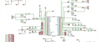
Good day to the author There are a couple of misunderstandings with diagram 1. The left-right input goes to R52 and R53 are the central cores, and the common core sits on the ground? 2 there is no information about the 6.3V filament power supply, how many are there for each type of lamp? 3 in the diagram shows where to supply power -70 and +350, and do +70 and -350 go into the circuit or not? some of the pins are unlabeled (end R29 R40)
Alexey 06-07-2014 17:52
Good day! I was interested in your article, I want to make the same amplifier, but I didn’t understand how to wind the output signal transformer from lamps (I have no experience in this). As I understand from the description, the power transformer and the output transformer are combined or what? I used one rectifier for both channels. There was no particular desire to wind another winding, just like the wires in particular. Paid more attention to capacitors instead. Nothing like this was noticed; I made do with one step-up winding. The output transformers are homemade, such as ts-20 ts-30, whoever has them, with a horseshoe-shaped core. Quote: We wind it this way: the primary is 94 turns with 0.47 wire, then 900 turns of the primary with 0.18 wire should turn out like this: 94/900/94/900/94/. We connect the primary to the secondary in parallel; we do not place any paper gaskets between the halves of the iron. From the description I didn’t figure out where the secondary is and where the primary is, since there are two of them in the description. If possible, please write a little more about the output trans or correct where the error is. Thanks a lot!
Ps Yuri Where it says 70 and 350 V, conclusions. Pay attention to which of them are grounded, this is not a minus, but the author meant the dash.
Sam 07/12/2014 19:14
I answer for Yuri. first: yes, the braid, aka the common core, sits on the ground. second: the power supply is made on a ready-made transformer from a black and white box of type TS-270. (270 watts). All windings on this transformer can be left. You just need to wind up the secondary winding so that the changes at the output are 300-320V. Those that are on it give 220, this is not enough. For incandescence we use the original winding. It will quite draw 5 amperes. All the filaments of the lamps are connected in parallel. third: 70V winding, plus connects to the ground common wire. -350 is supplied to the ground wire according to the diagram. I didn’t sign, I thought there would be no questions, everything seemed obvious.
#10 Sam 07/12/2014 19:31
in the description above I mentioned the TS 270 and that it was taken from a b&w lamp box. It has all the windings, if there is no 45 volt winding on this trance, we wind it ourselves
#11 Sam 07/12/2014 19:34
-70 is served where it is -70 on the diagram is not a dash
#12 Sam 07/12/2014 20:00
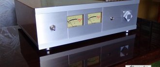
for ALEXEY.. there is only one power transformer; it is not in the photo, it is packed in an old case from a computer power supply, I wrote about this. and two output trances. For the output trance, it is best to take a trance with a horseshoe-shaped core, the same as the ts270, only smaller in size. If there is no such transformer, as I wrote above ts20 or ts30. then you can take any other with an approximate power of 30-40 watt, with W-shaped iron. Why is horseshoe-shaped iron better? Because four ready-made horseshoes have already been assembled and glued together. Sh-shaped is bad because if the plates have burrs, rust, crumpled, then when assembled they will short-circuit with each other, due to the fact that the insulation is broken. such a trance will not work as it should, and will bring nothing but disappointment. A prerequisite for such iron is unbroken plates. If there are no vehicle transaxles, then you can take ready-made factory ones like TVK-30. iron is the same. but it will take some time to disassemble them, because they are filled with paint and, in the worst case, epoxy. Now about the winding. First, 94 turns of the secondary winding are wound, the one to which the acoustics will be connected, then a layer of insulation, then 900 turns of the primary winding, then a layer of insulation , in the end you should have three secondary windings independent of each other and two primary windings. You draw conclusions from each winding so that you can then connect them as needed. Connect the secondary windings in parallel, just don’t mix up the beginning and end. beginning with beginning end with end. and you connect the primary windings in series, starting one with the end of the other, in the end you get one primary winding. and one secondary. Well, it seems that it couldn’t be clearer. there is nothing complicated even if you have never done anything like this
#13 Sam 07/12/2014 20:07
hint: if you can’t get rid of the AC background in the speakers, then look at the diagram with the name: entry-level tube amplifier, there is a circuit in the circuit design that completely eliminates this problem. You can easily find this diagram through Yandex.
#14 Vlad 12-06-2015 21:46
In reality, this lamp produces 6-7 watts of high-quality sound, the higher is slag.
#15 Sam 06/23/2015 20:01
for Vlad. most often the slag is obtained from the fact that they use low-quality elements, there is no knowledge, skill, and even more often by hand..
#16 Sound 08/15/2015 20:19
There is a significant flaw in the scheme. The anode load 6P14P is 22 kOhm, which is much more than optimal. This significantly increases the output impedance of the driver, which makes it less pleasant for the output tube. Driver distortion also increases greatly. The 6P45S lamp has a huge steepness. This means increased distortion. And indeed, with a power of more than watts, these distortions are both audible and visible even on the oscilloscope screen.
#17 sem 28-08-2015 08:03
for sound.. everything you wrote was in theory.. here everything was selected manually and it was the 22k anode resistor, try to assemble it yourself first, check and then criticize. for each 6p14p the value of the anode resistor turned out to be different. and everything was set up using an oscilloscope.
#18 Sound 01/17/2016 13:10
The Ra of the driver is 22 kOhm, while the optimal value for 6P14P is 5 - 5.2 kOhm. This means that this is fraught with huge distortions, including odd ones. Which will have a very bad effect on the sound.
#19 Sergey 01/23/2016 13:03
For beginners!!! Pay attention to the +350V power supply, both diode bridges are drawn in the wrong polarity!!! GOOD LUCK!!!
#20 admin 23-01-2016 22:27
Sergey, thank you, we corrected it in the diagram.
#21 Sergey 04/09/2017 18:01
Guys, please explain for the fool! Where the amplifier input is is clear, but I still haven’t figured out what to do with +70 and -350! And even though I’m just a beginner in this matter, this is the first time I’ve seen the ground wire taken from the 220 network through a capacitor! Or maybe there’s something I don’t understand, but the fact is that I can’t find a 1000 µF condenser or electrolyte with such a voltage!
#22 admin 09-04-2017 19:22
Sergey, all the answers to your questions are shown in the following picture (click to enlarge the picture):
#23 Varazdat 03-12-2019 17:00
Hello, please tell me what the problem is: I assembled such an amplifier, but one channel is louder than the second. It turns out that the channel in which the 4.7k resistor is installed is louder.
#24 admin 03-12-2019 21:05
Hello. Try swapping the amplifier inputs connected to 1x250 pass-through capacitors (C1, C26) - if now another channel becomes louder, then the reason must be sought in the signal source, signal wires or preamplifier circuit on a 6N3P lamp.
The circuit diagrams of the LF power amplification channels on 6P14P and 6P45S lamps are completely identical. If they play at different volumes, then there may be faulty or damaged electronic components installed somewhere.
Also try swapping the lamps in the UMZCH channels. Electro-vacuum devices have their own working resource and it is limited. If you installed used lamps, then it is possible that one of them is already on the verge of exhaustion and requires replacement.
#25 Varazdat 09-12-2019 21:26
I tried everything you said, the result is the same, just answer if you can why resistor R39 gets very hot
#26 Varazdat 12-12-2019 15:22
Everything worked, the circuit is good, just when assembling you need to take either the TS or two different transformers
#27 Vlad 20-12-2019 14:54
Hello, please tell me to select resistors by increasing the resistance or decreasing
#28 admin 20-12-2019 19:51
Hello. To select, use a variable resistor with a power of 0.5-1 W, having achieved the required parameters, then solder in its place a constant resistor with the same resistance obtained during the setup process.
For example, to select R23 and R34, which are 22K each, you can take a variable resistor of 36-56K, set its slider to the position to obtain a resistance of 22K. Then turn on the circuit, measure the voltage at the anodes of the lamps, as indicated in the article, slowly rotating the variable resistor knob to achieve the desired readings from the device. In place of the variable resistor, solder a constant one with the same resistance.
#29 Vara 24-02-2020 21:51
Hello, please tell me what the potentiometers R30 and R41 are for?
#30 sem 08-04-2020 15:33
for Vara R30 R41 they set the bias voltage on the control grid. in other words, the operating mode of the lamp is set. operating current
#31 Lutak 26-11-2020 20:19
Guys, tell me who assembled the amplifier and how it works?
#32 Lutak 26-11-2020 20:23
I want to collect one like this. I settled on this diagram. I wonder how many watts it is?
↑ Increasing power!
More power is definitely needed, but I’ll figure out the offset later.
Without thinking twice, I added another triode and it turned out to be an SRPP with a transformer output.
This option played louder, but still, it is not suitable for working with a turntable, where the output is ~500 mV.
In search of an answer, I came across an article by an unknown author, which proposed zero lamp bias. I tried it. And everything seems to be described correctly and intelligibly, but as soon as I saw on the milliammeter the current of 65 mA that the lamps were eating, I felt so sorry for my “forty-fives”!
In the same article, the author proposes to quickly change the resistance of the upper resistor, achieving a change in the spectral composition of the signal for listening to music of different genres. I tried it out of curiosity, switching resistors with values from 50 to 430 Ohms. There's something wrong with the ears again. I didn't notice any difference by ear. Again, according to physics, in the classic SRPP both resistors must be of the same value.
Total information
It was used in television equipment for the output stages of horizontal scanning of color televisions with a screen diagonal of 59-61 cm and a deflection angle of 90-110 degrees, as well as in the output stages of low-frequency amplifiers and amateur shortwave transmitters. A very close analogue of the European lamp EL509, but not a copy of it (it differs in the design of the cathode heating unit and has a fundamentally different grid design). The most powerful lamp for household equipment. Replaced the 6P42S lamp, which had insufficient reliability. It surpassed the GU-50 in output power with a lower voltage at the anode. Among receiving and amplifying lamps, it has the highest permissible anode current - 0.8A, and the emissivity of the cathode of the new lamp allows it to develop a current of up to 1.2A. One of the last lamps developed in the USSR for household equipment.
Oxide cathode, indirectly heated. Works in any position. Produced in glass baseless design. Service life - at least 500 hours. Pin base Magnoval type. Shtyrkov 9. The reliability of 6P45S lamps varied greatly depending on the manufacturing plant and the characteristics of the batch. A significant number of lamps did not reach their intended service life, but there were many copies that lasted many thousands of hours. During the years of mass distribution of ULPTsT TVs, the 6P45S lamp was especially scarce and TV owners often purchased it for future use (often more than one), despite the high price for those years - about 6 rubles.
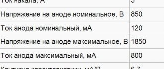
Main characteristics
- Filament voltage - 6.3 V.
- Filament current - 2.5 A.
- The anode current per pulse is 0.8 A.
- The anode voltage on a closed lamp is 7 kV.
- The power dissipated by the anode is 35 W.
Tsokolevka
1 and 8 - control grid, 2 and 7 - beam-forming plates, 3 and 6 - shielding grid, 4 and 5 - filament (heater), 9 - cathode, cap - anode.
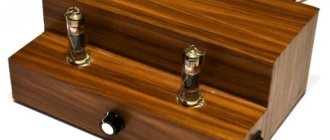
↑ Summary
I really liked the 6S45P lamp! To be honest, I expected more from Noem's 100GDSh speakers. But, in general, the amplifier paired with speakers sounds good. The main thing is that my daughter was happy!
There is an idea to try the 6S45P as a driver for the RR on the 6S33S-V with an interstage transformer. But that will be a different story.
Thank you for your attention!
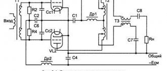
↑ Final SRPP scheme
So, I settled on the following diagram.
I didn’t bother much with the tone block - two-way with a finely compensated volume control at ALPS 50 kOhm.
Kenotron power supply was replaced with semiconductor power supply to reduce dimensions. The delay circuit for switching on the anode voltage has been repeated many times by the Datagorians. I took it as a basis and slightly adapted it to suit myself.
Total information
It was used in television equipment for the output stages of horizontal scanning of color televisions with a screen diagonal of 59-61 cm and a deflection angle of 90-110 degrees, as well as in the output stages of low-frequency amplifiers and amateur shortwave transmitters. A very close analogue of the European lamp EL509, but not a copy of it (it differs in the design of the cathode heating unit and has a fundamentally different grid design). The most powerful lamp for household equipment. Replaced the 6P42S lamp, which had insufficient reliability. It surpassed the GU-50 in output power with a lower voltage at the anode. Among receiving and amplifying lamps, it has the highest permissible anode current - 0.8A, and the emissivity of the cathode of the new lamp allows it to develop a current of up to 1.2A. One of the last lamps developed in the USSR for household equipment.
Oxide cathode, indirectly heated. Works in any position. Produced in glass baseless design. Service life - at least 5000 hours. Magnoval 9-pin socket. The reliability of 6P45S varied greatly depending on the manufacturer and the characteristics of the batch. A significant number of lamps did not fulfill their intended service life, but there were many copies that lasted many thousands of hours. During the years of mass distribution of ULPTsT TVs, the 6P45S lamp was especially scarce and TV owners often purchased it for future use (often more than one), despite the high price for those years - about 6 rubles in the early 1980s (until April 1, 1991 - 9 rubles).
Lamp 6P45S. Label. Front side.
Lamp 6P45S. Label. Inner side.
Main characteristics
- Filament voltage - 6.3 V.
- Filament current - 2.5 A.
- The anode current per pulse is 0.8 A.
- Anode voltage - up to 300V.
- The power dissipated by the anode is 35 W.
Tsokolevka
1 and 8 - control grid, 2 and 7 - beam-forming plates, 3 and 6 - shielding grid, 4 and 5 - filament (heater), 9 - cathode, cap - anode.
gold - 0.028675 g
platinum - 0.001508 g
Content of non-ferrous metals in one lamp
brass - 1.3 g in the upper terminal cap
molybdenum - 7.5 g in grids
nickel and its alloy - 13.3 g in the cathode, anode chamber, beam-forming plate, gas absorber, jumpers, yoke.
↑ Acoustic wires from PShch-16
I don’t trust expensive overseas cables with a cavalcade of “nines” after the decimal point. Therefore, I support the domestic manufacturer. Wire PShch-16 is an annealed copper braid, although not very cheap (up to 2000 rubles per 1 kg).
I got carried away with the cross-section, I could have gotten by with PShch-10, it’s easier to buy, and the footage per kilogram would have been almost 2 times larger (10.7 m of wire in 1 kg). The wire is wrapped in a silicone tube 8x10 mm. Copper U-terminals are soldered to the ends of the wires.
↑ Acoustic systems "ORTHO" for 100GDSh-33-16
I considered the possibility of using speakers 4A-32, 6GD-2, 4A-28. I chose the 100GDSh-33-16 in ORTO design. I saw the design in the article “Universal tube sound amplifier kit: phono preamplifier, PP/SE, ORTO, diagrams and drawings” by our citizen Yuri (titpol). I ordered the speakers from Novosibirsk.
A pair of speakers with shipping to St. Petersburg cost about 10 thousand rubles. Probably the speakers are not bad, it’s a pity there was no opportunity to compare them with the 4A-32. But it seemed to me that the stated sensitivity of 97 dB is slightly too high. I didn’t measure it, I just compared it with 2A-12U4, purely by ear.
Well, the highs, in my opinion, do not reach 17 kHz. I discovered this when comparing it with the 10GDV-4-16, whose cutoff frequency was set to 17 kHz. Heaven and earth! Overall, both speakers complement each other well. The 100GDSh has scale, good mids and pressure. The bass, I hope, will not let you down either after the appropriate acoustic design. I am again convinced that “big sound” is inherent in large speakers.
I won’t dwell on the speaker design, read the original article. Just a few touches. The inner surface of the boxes was covered with STP sound insulation 5 mm thick on a sticky base purchased at an auto parts store.
The internal volume of the boxes was filled with cotton bags (I bought 5 kg of mattress cotton at the Matraskin factory).
Internal installation was performed using PShch-8 wire.
The decorative panel around the HF head is made from the cover that remained from the Gainta 140x100x75 mm case. On the same panel I installed a P2G3 6P2N switch, which allows you to choose the cutoff frequency of the tweeter at will, 10 kHz, 14 kHz, 17 kHz, or turn it off altogether.
To protect the speakers from playful feet, just in case, I placed acoustic fabric over the slatted frame.
↑ Finalization. Input stage on 6N23P
As I already wrote, the main signal source is a vinyl turntable with an output of 500 mV. This means the 6S45P-E needs to be pumped up. It didn’t take long to choose an input lamp - it’s 6N23P-EV.
My 6N23P copies had a gain of 34, which, taking into account the attenuation in the tone block, is sufficient with a margin. I decided to choose the working point in a more linear section. 6N23P-E mode: Ua = 65…70 V, Ucm = – 1V, Ia = 8…10 mA. As a result, the design underwent minor changes.
In place of the battery compartments, I cut a hole for the PLC-9 socket. I replaced the two-section toggle switches with single-section ones, which, if necessary, turn off the tone control and volume control. I increased the bias of the bottom lamp a little more by installing a 105 ohm cathode resistor. The anode current was about 25 mA. The output power into an 8 ohm load at an input signal level of 1 V was 1.7 W. I was very pleased with the sound in the headphones - powerful, spacious with good bass.
↑ Listening, analysis, conclusions
I listened to the amp for several days.
At the same time, I measured the frequency response. The frequency band is from 18 Hz (my generator can’t produce lower) to 22 kHz (it can’t go higher either) with an unevenness of 1 dB. The output undistorted power into an 8 ohm load was 1 W. At one and a half watts, distortion of the signal shape is already observed, although at the primary of the output trance the sine is ideal. Conclusions:
The sound quality is decent; power is still not enough; We will have to abandon the battery bias in favor of freeing up space for installing a preliminary amplification stage.