Jazz-rock'n'roll improvisations
There is such a way of spending time - looking at all kinds of equipment online: Marants, Denons, Yamahas, Rotels, Neds, etc. Such a remake surrounds you on all sides, hangs over your head, “begging” you to buy, change and buy again. Which is what happens sometimes.
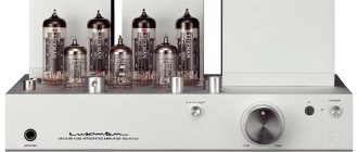
But in parallel with this, I was in the process of refining my technique. Using audiophile and other methods, I tried to obtain a sound that, in my opinion, corresponded to the level of quality I needed. I wanted a dynamic (driving), warm, detailed, transparent sound with an unshakable stage. Something like this... And it finally happened. I got the sound I needed on transistor class AB. So, what is next? Dead end... If the sound is warm and detailed, transparent and driving, then in the conditions of a particular room it is impossible and absurd to make it even more what it already is, because all this is already there. But you always want something more... And there is a way out! Japanese amplifier Luxman 550A. Transistor class A. Only 20W per channel. But what watts! Distortion – 0.005%. Everything inside is not just correct, but perfectly correct. Large dial indicators are pleasing to the eye. Hull color and finish. In short - Hi-End! $5700!!! Wait…
In my case, it’s more interesting, that’s for sure, to get the same sound on a different type of equipment. Lamps! Lamps, lamps! It's inspiring.
For every self-respecting music connoisseur should have a tube amplifier in his arsenal. This inspired me, especially the creations of those brave gentlemen who presented their projects online.
In order not to reinvent the “bicycle”, it was decided to create an amplifier from ready-made circuit solutions with the introduction of our own ideas about what is “correct”.
The purpose of this article is to continue the conversation started in my article published in the magazine “Radio Amateur” No. 9 for 2003.It provided a description and a diagram of a relatively simple tube high-quality single-ended power amplifier designed by A. Manakov.
Judging by the reviews, radio amateurs who built this amplifier would like to continue their acquaintance with tube designs, systematize their knowledge and get answers to frequently asked questions.
To continue our dialogue, let's first understand what we would like to get from an amplifier, what parameters are most important, where and for what it will be used, what the costs of its manufacture are, etc.
As you know, the world is divided into two opposing camps - on the one hand, fans of single-ended amplifiers, on the other, their opponents are fans of push-pull circuitry.
The arguments of opponents of single-cycle devices are based on objective data. These are low output power, limited frequency range, high level of distortion, etc. (you can read more about this in any amateur radio literature).
Supporters of single-cycle devices, on the contrary, point to their purely subjective qualities.
These are musicality, sound transparency, softness, melodiousness, etc.
Let's take a closer look at the main pros and cons. Simple logic dictates that the more power, the better, and the distortion, accordingly, is the opposite. It is known that high output power is achieved by switching the amplifier to AB mode, and this leads to an increase in distortion of all types. You can object to me and apply negative feedback, but I want to say right away that using OOS will not improve sound quality (which is what we ultimately strive for), but will replace some distortions with others. Any mediocre transistor amplifier can easily provide 50-100 W of output power with a harmonic distortion of about 0.003-0.05%, but they sound bad. Their sound is devoid of color, the sound is flat, devoid of volume and emotionality.
Studies have shown that an acoustic system with a sensitivity of 90 dB and higher, together with a power amplifier of 5-10 W, is capable of creating a sound pressure in a small room (which in most cases are the rooms in our apartments) comparable to the sound pressure created by a symphony orchestra in a concert hall . I won’t believe anyone who says that he needs even more (here we are not far from ear injuries).
Now is the time to talk about the level of nonlinear distortion. Psychoacoustics argue that the noticeability of nonlinear distortions by ear for harmonics of different orders is not the same. Experts do not notice 1% of the second harmonic, but ordinary people begin to feel it from about 4-5%. It is also necessary to say that the aural noticeability of some harmonic of a higher order is proportional to the square of its number. It can be easily calculated that 0.1% of the tenth harmonic and 2.5% of the second harmonic will cause a commensurate deterioration in sound quality. It is also important that the spectral combination of harmonics smoothly decreasing in level (the third after the second, the fourth after the third, etc.) is most harmonious for the human ear. This is where the unpleasant conclusion follows: the information provided in equipment data sheets about the general level of nonlinear distortion, without indicating the spectrum of these distortions, does not say anything about the sound quality as a whole. So don’t chase 0.0000…..%, but listen and analyze.
Any literature describes four main advantages of push-pull tube output stages:
- a) absence of permanent magnetization in the output transformer.
- b) increased power output.
- c) compensation of even harmonics in the output signal.
- d) reduced sensitivity to supply voltage ripples.
Let's consider all these advantages in detail, taking into account modern trends in the development of the element base and the goals that we are pursuing (let me remind you, sound quality).
Just as in the previous paragraph, I will analyze each point separately:
- a) constant bias reduces the inductance of the primary winding, and forces the iron to work in a particular hysteresis cycle, in other words, in a mode with increased linearity, especially on small signals, without the inherent step in the push-pull mode when crossing zero (in the literature it is often called “pure class A” ). As you understand, compensation for the decrease in inductance is an increase in the size and weight of the output transformer, which is quite normal (for us, the main thing is sound quality).
- b) the power can be easily increased by connecting several lamps in parallel.
- c) compensation of even harmonics (but nowhere is it written that as a result of this -
- protrusion of odd ones) due to the characteristics of our hearing, leads to
- subjective deterioration in sound quality.
- d) the increased sensitivity of single-cycle devices to pulsations is easily overcome
- anode voltage filtration. Modern high-capacity electrolytes are small in size and cost.
A strange thing, an unexpected conclusion arises that the disadvantages of single-ended amplifiers, upon closer examination, turn out to be not disadvantages at all, but advantages. Those that remain can be easily eliminated by slightly increasing the size and weight.
In any case, the choice is yours, dear readers.
For me personally, it is natural that a high-class amplifier that sounds excellent and conveys the slightest nuances of sound has decent weight and dimensions. I'm not against transistor amplifiers by any means (I've made countless of them), but the tube triode is the most linear amplifier element available today.
So, I turn to the description of another power amplifier, designed by my friend A.I. Manakov.
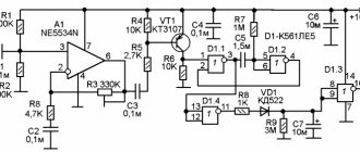
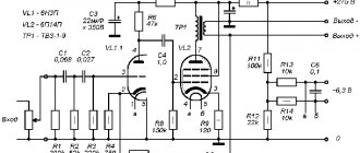
Scheme
The power supply is located on a separate board and contains a double electronic choke with an anode voltage delay according to Chugunov’s design. On the same board there is a bias voltage source and a constant voltage stabilizer for the driver lamp. The nutrition spectrum turned out to be very clean.
The entire circuit is powered by two transformers: the main one - TAN-43 and an additional one, 10V, for illuminating the indicators and for the filament stabilizer of the driver lamp. As a second one, you can use TN-30.
The amplifier itself is made as a separate unit, according to Oleg Chernyshev’s circuit, with a fixed bias of the output lamps. Capacitors C4 provide high frequency correction. For a linear characteristic, 100 nF is sufficient. I have 200 nF - a rise of 1db.
Dialer volume control, based on a Soviet instrument paired switch with ten positions. I first disassembled it, cleaned it, lubricated it with thick silicone grease and installed a softer spring. The entire structure is surrounded by a screen made of copper sheet. The total resistance of the regulator directly affects the level of the lowest frequencies and the noise level. I recommend its resistance to be in the range of 15 - 24 kOhm.
Output transformers TV-2Sh (TVZ-1-9). We selected from seven pieces according to the maximum signal level and frequency range.
Input selector on a toggle switch for two sources. Of course, there is an opportunity and place to build a relay system if you want in the future.
The wires running from the input jacks to the selector are laid in a thick silver-plated copper screen from some kind of military radio cable.
The body wires from all blocks and screens and from the front panel converge in the center of the power supply at the minus of the capacitors.
The relative position of all nodes, blocks and connectors was determined by the minimum noise level and monitored using a spectrometer with subsequent comparative RMAA measurements.
Instead of the Oleg Chernyshov block, if you don’t like its sound or for experimentation, you can install an amplifier block according to such a common scheme https://cxem.net/sound/amps/amp46.php or any other single-cycle corresponding to the current consumption.
PSU components installed on radiators are located with the heat sink facing upward. When installing these components vertically with other radiators, it is necessary to change the layout of the printed circuit board tracks. R24 – adjustment of the filament voltage L1 6.3 V. R17 – adjustment of the output voltage of the electronic choke 300V. C14 – determines the time for setting the operating mode of the anode voltage. R11 – setting the pentode current. At anode - 300V. On R10 48mV. R12 – setting the indicator level to 0db (2W) 2.85V with a 4 ohm output load.
Scheme. Single-ended tube amplifier made from affordable parts
Of the possible options, we preferred an amplifier based on 6PCS output beam tetrodes in a triode connection. This device was the prototype of the serial model “Avant Electric Nostalgia”, which differs from it in some modifications caused, in particular, by the technological requirements of the production series.
Main technical parameters of the amplifier:
output power 7 W with a nonlinear distortion coefficient of 6%, sensitivity 0.4 V, operating frequency band at full power no worse than 12 Hz - 30 kHz without OOS.
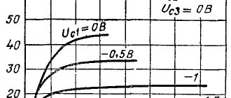
We chose the 6CCD output lamp, firstly, for its availability and low (about 20 rubles on the St. Petersburg radio market) price. Secondly, due to the fairly high linearity in the triode connection, I have a promising harmonic spectrum (relatively high second harmonic and low third). Let us recall that this lamp, or rather its prototype 6L6, was developed specifically for use in audio paths. And thirdly, for its warm (this is the time to remember about the spectrum of harmonics) and - still, one cannot do without this word - “musical” sound, even in comparison with such serious rivals as the EL34 and 6550. Two relative disadvantages of this lamps in triode connection - we overcame the low output power (3.5 W) and a fairly high internal resistance (about 1.5 kOhm) by connecting two lamps in parallel. It should be noted that among Russian radio amateurs there is a widespread, in our opinion, unfounded opinion that parallel connection of lamps is inadmissible. Without wanting to go deeper into a discussion on this topic, let's give a simple example. One of the most expensive (after all, 330 thousand dollars) amplifiers, respected by everyone, namely “Gaku-On”, has two lamps connected in parallel at the output, which does not at all prevent its lucky owners from enjoying music. One way or another, by connecting 6CCD lamps in parallel, we got an internal resistance of 750 Ohms and 7 W of triode power. Well, why not “three hundred”?!
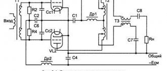
Let's take a closer look at the diagram.
The input stage, also known as the driver, is made according to a circuit with a dynamic load (SRPP) on one of the best domestic small-signal triodes 6N9S. The use of SRPP is explained not by any special preference for such stages, but by the fact that we tried different options (one triode with anode load, parallel connection of two triodes, etc.) and settled on SRPP. as providing the best, in our opinion, sound quality. The output stage, as mentioned above, is made of two 6CCD beam tetrodes in a triode connection. In order to minimize nonlinear distortion, the output lamps are selected in pairs based on anode current and slope with an accuracy of 1.5% and, if necessary, are also replaced in pairs. For those who do not have the opportunity to select lamps, we advise you not to get upset and use those lamps that you have (preferably from the same batch), since the spread of lamp parameters leads to an increase mainly in the second harmonic, which should not radically deteriorate the sound. The operating modes of the output lamps we have chosen may, at first glance, cause confusion. In particular, the voltage on the second grid is 100 V higher than the value specified in the reference book. In our justification, we refer to article [4], which proves the possibility of using pentodes and beam tetrodes in a triode connection exceeding some reference modes without a significant reduction in service life lamp operation.
Our many years of experience working with lamps confirms this; moreover, the cost of 6CCDs is not so high (unlike, say, 300V), and replacing even the entire set of lamps once every few years is unlikely to have a noticeable impact on anyone’s budget. The load of the output stage is a transformer.
Output transformer
, of course, is the most important element of the design. Perhaps no less depends on it than on the output lamp. In our version, it is made on an W-shaped core made of transformer steel with a thickness of 0.35 mm (an SH-core on steel E310-330 is quite suitable), the width of the middle rod is 25 mm, the height of the camp is 40 mm. The primary winding consists of four sections of 510 + 1190 + 1190 + 510 turns of PEV or PETV wire with a diameter of 0.28 mm. Between them there are three sections of the secondary winding of 216 turns of wire with a diameter of 0.71 mm. From the 130th turn you can tap for a 4-ohm load. All sections of the primary winding are connected in series, the secondary - in parallel. Capacitor paper (ordinary paper can also be used) 0.3 mm thick is laid between the windings. After winding, the reel is impregnated with technical wax (a mixture of paraffin and perlin). The core is assembled: W-plates and I-plates separately, with a gap of 0.25 mm between them using a plate of insulating material.
This is not the only possible output transformer design. It is quite acceptable to use other designs, for example, in recent years, a two-coil version with a PL core has become widespread, which has certain advantages (as well as disadvantages). In this case, you will have to calculate the transformer yourself. Let us remind you that you can find the information necessary for the calculation in [5], and we will also indicate the main parameters. First of all, this is the AC resistance of the primary winding of 2.5-3.0 kOhm, as well as the DC bias current of at least 120 mA. The only caveat: do not use cores with an average core area of less than 10 cm2 (overall power less than 150 W), otherwise you are unlikely to get acceptable performance at low frequencies.
The power supply is assembled on the 5TsZS kenotron
, which is no coincidence. Practice shows that kenotron power supply can significantly improve the sound quality of an amplifier, no matter what semiconductor diodes you have previously used. It is no coincidence that the most expensive models use kenotrons. For the power transformer we used a magnetic circuit Ш25×50, the primary winding contains 770 turns of PEV wire with a diameter of 0.63 mm, the step-up winding - 1340 - 1340 turns of wire with a diameter of 0.315 mm, the filament windings - respectively, 19 turns of 1.25 mm wire to power the kenotron, 24 turns of the same wire to power the filament of the output lamps, and 24 turns of 0.71 mm wire to power the filament of the input lamps. You can also use another magnetic circuit from a transformer with a power of at least 150 W, making the calculation yourself.
All parts are mounted on an aluminum chassis and interconnected using hinged mounting. Try to make maximum use of the terminals of the elements themselves: where they are lacking, use MGTF-0.35 wire, paying special attention to the “ground” circuits. Basic requirements for installation: the wires should be as short as possible and under no circumstances should closed circuits be allowed, otherwise you will end up with not an amplifier, but a radio receiver. A circuit assembled without errors does not require configuration. It is only advisable to check the voltages and currents at the indicated points using a tester. If the measured values differ from those shown in the diagram by no more than 10%. - Everything is fine. Gross differences most likely indicate an installation error or a malfunction of any element.
Before using for the first time, check the installation carefully. This will relieve you from the thrill. If, when turned on, your amplifier did not give any alarm signals (burning smell, sparks, loud clicks, etc.), let it warm up for 10-15 minutes and start taking measurements.
With proper installation of ground circuits, the background level in your speakers should be quite low. With a speaker system with a sensitivity of 90 dB, it is only audible if you bring your ear close to the subwoofer. Otherwise, you will have to experiment with the placement of parts and wires, which can sometimes even take several days. But, one way or another, this is a solvable task, and, therefore, you can cope with it.
Now let’s touch on such a sore point as the types of elements used
. Why sick? On this matter, we had to read and hear directly opposite opinions, starting with the fact that our domestic components are no worse (or even better) than the most expensive and prestigious foreign ones, and ending with the fact that without “Black Gate” and “Multicap” there is nothing even trying to get a decent sound. A detailed consideration of these issues is beyond the scope of the article, and we will limit ourselves to only some specific recommendations based on our personal experience.
The types of elements indicated in the diagram guarantee you a certain initial level of quality, quite comparable to that inherent in some expensive foreign models. And then, based on your tastes and capabilities, try to rise to a higher level. Just don't ask too much of this scheme and it won't disappoint. So, let's start in order.
The potentiometer at the input can radically affect the sound quality. Unfortunately, a worthy replacement for the expensive “ALPS” can only be a step attenuator, say, based on domestic reed switches with gold-plated contacts.
Replacing the transition capacitance has no less effect on the sound. If we have the opportunity, we recommend trying “Multicap RTX” or “Jensen”, known no less than “Audio Note”. They sound very different, but each of them, in our opinion, deserves its high reputation (and high cost). With all our patriotism, we cannot agree with those who claim that our K40U-9 (KBG, FT, FGTI and many others) are better (or, alternatively, no worse) than the above-mentioned “Multicap”, “Jensen”, etc. We assume that statements of this kind are caused by the insufficiently high quality of the sound paths used during testing.
Our MBGOs (MBGV, MBGN, MBGCh, even better KBG-MN, etc.) have proven themselves to be excellent in the power supply, if you close your eyes to the fact that they will take up half the room. Despite our endless respect for the “Black Gate” series “WKZ”, we would not hesitate to recommend them due to their prohibitive cost. We advise you to save them for more advanced designs, and put something simpler here, for example “Rubicon” or “Nichicon”.
And finally, if for installation you use some OFC wire from a well-known company (to our taste) and “WBT” or “Audio Note” solder, it will not get any worse.
A few words about acoustic systems,
which can be used with this amplifier.
They say that only highly sensitive (95 dB and above) speaker systems can unlock the capabilities of low-power tube amplifiers. Undoubtedly, the higher the sensitivity of your speakers, the less power is required from the amplifier to create the same sound pressure level and the less distortion, accordingly, will be. But the problem is that a more sensitive acoustic system does not always turn out to be better in sound. How to be?
In the home set of one of the authors, the described amplifier worked for a long time with speaker systems based on Peerless dynamic heads with a sensitivity of 88 dB, reproducing music of various genres, including hard rock at high volume, and there were no problems with transmitting dynamic contrasts. At the Russian Hi-End 2000 exhibition, the Nostalgia amplifier was demonstrated complete with speaker systems with a sensitivity of 87 dB in a hall of no less than 50 m2 and, to the amazement of many, including ours, on most soundtracks it was able to provide the necessary volume, without going into clipping. So if maximum volume is not your main criterion for assessing sound quality, use the speaker system that you have, and you may be pleasantly surprised. In fact, you shouldn’t be surprised; the subjective perception of the sound volume of tube amplifiers differs significantly from the perception of the volume of transistor amplifiers. The most commonly called subjective power rating “Nostalgia” is 35-40 W. We hope that we have dispelled your doubts.
There is another problem, in our opinion, no less important. The combination of a high (3 ohm) amplifier output impedance with a high quality speaker system can sometimes lead to an unwanted boost at low frequencies, simply put, to humming. In such cases, the blame most often falls on the amplifier, although it seems to us that the speaker system is no less to blame. More precisely, this is a problem of mutual matching between the amplifier and the speaker system. There are several ways to solve this. The simplest is the introduction of shallow feedback, which reduces the output impedance of the amplifier to an acceptable level. How can this be, you say, since we just refused feedback for ideological reasons. Well, in this case we propose to make a compromise, given that in most cases an OOS depth of 2-3 dB is sufficient. But for convinced opponents of OOS, we will present a more radical solution - to independently manufacture an acoustic system with a reduced quality factor specifically for operation with amplifiers without feedback. If such a prospect does not frighten you, we, for our part, are ready to publish one of the possible design options for such a system on the pages of the magazine.
Literature
1. Likhnitsky A. Power. Part 1. “AudnoMagazin.”N” 2 (7) 96. 2. Frankland S. Single-Ended Vs Push-Pull. Part 1. “Stereophile” 12/1996. 3. Tsykin G. Electrical signal amplifiers. 1963, 4. Troshkin N. Triode from scrap materials. “Class A”, October 1997. 5. Tsykin G. Low frequency transformers. 1955.
Specification
Amplifier R1 - MLT 0.5 470 kOhm C1 - 47 uF, 450 V R2, R3 - MLT 0.5 1.5 kOhm C3 - 1000 uF, 6ZV R4 - MLT 1 20 kOhm C2 - 0.15 uF, 250V R5 - MLT 0.5 220 kOhm C4 - 300 pF (K78) R6, R10 - MLT 0.5 1.0 kOhm R7, R11 - MLT 1 100 Ohm R8, R12 - MLT 0.5 22 Ohm R9 - PEV 10 240 Ohm R13* - MLT 0, 5 30-120* kOhm V1, V2 - 6N9S V3, V4 - 6PZS S2 (K72 P6, K72 P9) S1, SZ (K50-27, K50-37, K50-42, Rubicon, Nichicon, Jamicon)
POWER SUPPLY VI - 5TsZS L1, L2 - 2.5 G x 0.14 A C1, C2, SZ - 220 µF, 450 V C4 - 47 µF, 100 V R1 - MLT 1,300 kOhm R2 - MLT 1 - 43 kOhm C1, C2, SZ ( K50—27, K50—37, K50—42, Rubicon, Nichicon, Jamcon)
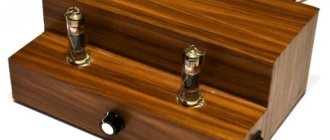
Frame
Chernyshev called his amplifier Pokemon - a small pocket monster. In my case, due to almost complete ignorance of what I was doing and what I wanted, I ended up with an amplifier for a full-size cabinet. Or the pocket should be larger... I didn’t have a goal to compact all the parts for compactness. Moreover, if you want to change something, the case will not be a hindrance.
The body was assembled from fiberglass. It couldn't have happened any other way. But it turned out to be a fairly stable structure. Chassis – 6mm. Rear wall – 4mm. Top cover (2mm). Its color and texture, in my opinion, are acceptable and do not require painting. The front panel is made of foil fiberglass (2mm), sheathed on the front with aluminum (2mm). In addition, various aluminum corners were used for reinforcement and decoration. The chassis, of course, will be much more convenient if it is made with windows for boards, as they did in the old days. To do this, you can safely use thick plywood rather than expensive fiberglass. The ventilation grille is a soap dish. The supporting legs are bearings (Primare is resting).
↑ Where to start?
Where does the manufacture of a tube amplifier begin? It depends on you, but for me, the fundamental basis of an amplifier (in the form of a complete structure) is usually the housing. Here, too, it all started with him. I drew a hand-drawn sketch of a box with the dimensions I required (430x280x80mm) and three casings for transformers measuring 120x120x110mm and ordered production from a friend at a local hardware company. The case was made for me conscientiously. We bent and welded it from 2mm steel. I later remembered my friend with “kind” words more than once when I cut and drilled holes for mounting lamps, transformers, connectors, etc. This is what the case looked like when we tried on lamp panels and transformers on it.
What is the result?
What do we see and hear? Despite the lack of fundamental perfectionism, and somewhere, a formal approach, the result was a very beautiful and stylish product, in my opinion, which demonstrated a fairly powerful and beautiful sound, even on low-sensitive (85db) speakers. Perhaps this is, of course, not the Luxman-550A, but one can note the high detail and transparency of the sound, warmth and dynamics, as well as the “indecent” absence of even a hint of noise or background. In general, according to individual feelings, after listening, this is a very good result.
↑ Transformers weekend
The second main part of the amplifier is transformers: a pair of outputs and a power one.
To make output transformers, I disassembled and unwound a pair of identical-sized transformers from computer uninterruptible power supplies from the famous APC company. Fragment excluded. The full version is available to patrons and full members of the community.
The result is a transformer that provides a 4.5 kohm anode load and outputs for connecting speakers with a resistance of 4 and 8 ohms.
In order to ensure the same parameters of the output transformers, I divided the core plates equally and then mixed them evenly. A plate from one transformer, a plate from another, and so on. This way you can be sure that both cores will have exactly the same parameters.
A non-magnetic gap of 0.15 mm is introduced into the transformer between the “W” plates and “I” jumpers. After assembling the transformer, it is lowered into a pan with molten paraffin for about an hour in order to be thoroughly soaked.
↑ Parts used and installation
A few words about the parts used.
Resistors PTMN, C2-29 in the signal circuit. The rest of the OSMLT, which were at hand. Capacitors in the Nippon Chemi-Con power supply have a rated voltage of at least 450 Volts. These are fairly high-quality capacitors that did not require film/paper bridging, although no one forbids doing this. You can't ruin paper with oil, as experienced lamp makers say. The amplifier is completely mounted. First, the power supply is assembled on a separate metal chassis. This chassis, after testing, is fixed inside the housing. In order not to drill unnecessary holes, the power supply unit is attached to the same screws that secure the power and output transformers.
The chokes in the power supply for powering the final stage are taken from standard Dr2-LM from tube TVs. The throttle for stabilizing the screen grids is also a unified D36-20-0.05. Instead of iron chokes, you can use smoothing filters on field-effect transistors - the so-called “electronic chokes”. I took what was available in the nightstand.
After installing the power supply wiring, the amplifier itself is mounted. Insulating stands are screwed onto the screws that secure the lamp panels and I solder a thick copper single-core wire to them - a ground bus. Subsequently, all other parts are soldered directly onto the petals of the lamp panels and to this bus, where required. This is what the assembled amplifier looks like from the basement.
After completing the installation, we put the amplifier on its feet, connect the acoustics, the signal source and you can start listening. This is what the finished amplifier looks like. Glamor lovers may not like the slightly “TANK” look. The weight, by the way, also corresponds - more than 20 kg. It can be used for morning warm-up, and to make it more convenient to handle, it has a pair of strong iron handles.
↑ Power transformer
The power transformer is made on the basis of a Ш40x40 core. It was calculated in the Power Trans program. All necessary data for winding can be seen in the program window.
For a power transformer, almost any transformer with an overall power of at least 150 W is suitable. You can use power transformers from tube TVs such as TSSh170 or TS180. All secondary windings must be removed from them and new ones must be wound in order to obtain the required voltages.