Nikolay Petrushov
TL494 (Texas Instruments) is probably the most common PWM controller, on the basis of which the bulk of computer power supplies and power parts of various household appliances were created. And even now this microcircuit is quite popular among radio amateurs who are building switching power supplies. The domestic analogue of this microcircuit is M1114EU4 (KR1114EU4). In addition, different foreign companies produce this microcircuit with different names. For example IR3M02 (Sharp), KA7500 (Samsung), MB3759 (Fujitsu). It's all the same chip. Its age is much younger than TL431. It began to be produced by Texas Instruments somewhere in the late 90s - early 2000s. Let's try to figure out together what she is and what kind of “beast” this is? We will consider the TL494 chip (Texas Instruments).
So, first, let's see what's inside.
Compound.
It contains:
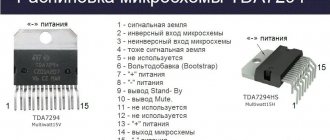
— sawtooth voltage generator (SPG); — dead time adjustment comparator (DA1); — PWM adjustment comparator (DA2); — error amplifier 1 (DA3), used mainly for voltage; — error amplifier 2 (DA4), used mainly for the current limit signal; — a stable reference voltage source (VRS) of 5V with external pin 14; — control circuit for the operation of the output stage.
Then, of course, we will look at all its components and try to figure out why all this is needed and how it all works, but first we will need to give its operating parameters (characteristics).
What is needed for making
More than 90% of the components for a laboratory worker are already in the computer power supply. The rest will have to be selected for a specific scheme (the elements are inexpensive and there will be few of them), but you will definitely need:
- two potentiometers for adjusting voltage and current;
- several oxide capacitors for a voltage of at least 35 volts (preferably 50+) with a capacity corresponding to the standard capacity of the +12 volt channel elements (or more if they fit in dimensions);
- terminals for connecting the load (it is convenient to use red for the positive terminal and black for the negative);
- voltmeter and ammeter for measuring output parameters (you can use analog instruments, you can use digital ones, but it is more convenient to use a double voltmeter-ammeter unit).
Digital current and voltage indicator.
The equipment you will definitely need is a multimeter . It wouldn’t be superfluous to use an oscilloscope to check the presence of output pulses on the PWM chip and its response to the control action if something goes wrong. You will also need a soldering iron with a set of consumables and small plumbing tools (a set of screwdrivers, wire cutters, etc.).
Recommended operating parameters.
| Options | Min. | Max. | Unit Change |
| VCC Supply Voltage | 7 | 40 | IN |
| VI Amplifier input voltage | -0,3 | VCC – 2 | IN |
| VO Collector voltage | 40 | IN | |
| Collector current (each transistor) | 200 | mA | |
| Feedback current | 0,3 | mA | |
| fOSC Oscillator frequency | 1 | 300 | kHz |
| CT Generator Capacitance | 0,47 | 10000 | nF |
| RT Generator resistor resistance | 1,8 | 500 | kOhm |
| TA Operating temperature TL494C TL494I | 0 | 70 | °C |
| -40 | 85 | °C |
Its limiting characteristics are as follows;
Supply voltage………………………………………………………..41V
Amplifier input voltage……………………………(Vcc+0.3)V
Collector output voltage…………………………..41V
Collector output current………………………………………250mA
Total power dissipation in continuous mode….1W
Components of a switching power supply for tl494
The power supply can be divided into 3 parts:
Internal power supply
These power supplies are needed to power the cooling fan, PWM controller and voltammeter. Any power supply with low power will fit here. It’s better, of course, not to assemble your own but to use ready-made solutions, for example, you can take an AC-DC converter.
2 Control unit.
The block consists of a TL494 and a driver with 4 transistors.
The connection diagram for the TL494 is very simple; this connection diagram is quite common among radio amateurs. Using resistor R4, the voltage is adjusted from 0 to the maximum value, and using R2, the maximum current value is set. Resistors R11 and R12 can be used multi-turn.
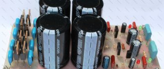
The control unit can be assembled on a separate board.
Control unit printed circuit board
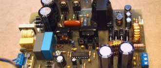
3 Power section
Most of the parts can be taken from an old computer power supply; we also take the input filter, rectifier, and capacitors from it.
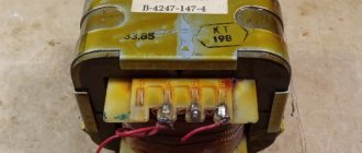
Next, we need to make a power switch control transformer. Most radio amateurs are scared by the fact that they will have to make a transformer. But in our case everything is simple.
To make a transformer you will need a ring R16 x 10 x 4.5 and MGTF wire 0.07 sq. mm. We take the wire in 3 pieces of 1 meter each and make 30 turns in 3 wires on the ring.
Inductor L1 is also wound onto a ferrite ring with a copper wire 1.5-2 meters long and 2 mm in cross-section. This winding will allow you to achieve approximately the required inductance.
Many power supplies have a second choke on a ferrite rod; you can use it as L2.
The power transformer is also taken from the power supply from the computer, but the output voltage will be 20 Volts. In order to get 30 Volts, the power transformer needs to be rewound. For high currents, it is preferable to use ferrite rings.
↑ Total
That's it, you can close the roof. This device can be used both as a laboratory power supply and as a battery charger. In the latter case, resistor R10 must be used to set the final voltage for a charged battery (for example, 14.2 V for a car acid battery), connect the load and set the charging current with resistor R4. In the case of a charger for car batteries, resistor R10 can be replaced with a constant one.
In some instances, the transformer hummed; this effect was eliminated by connecting a 0.1 µF capacitor from pin No. 1 DA1 to the housing (GND) or connecting a 10,000 µF capacitor in parallel with capacitor C3.
↑ Features of the pulsed version of EN
Analog electronic loads are certainly good, and many of those who used electronic loads when setting up power devices appreciated its advantages.
Pulse power supplies have their own peculiarity, making it possible to evaluate the operation of a power supply under a pulsed load, such as, for example, the operation of digital devices. Powerful audio frequency amplifiers also have a characteristic effect on power supply devices, and therefore it would be nice to know how the power supply, designed and manufactured for a specific amplifier, will behave under a certain specified load. When diagnosing power supplies being repaired, the effect of using pulsed EN is also noticeable. For example, with the help of pulsed EN, a malfunction of a modern computer power supply was found. The declared malfunction of this 850-watt power supply was as follows: the computer, when working with this power supply, turned off randomly at any time when working with any application, regardless of the power consumed at the time of shutdown. When tested for a normal load (a bunch of powerful resistors of +3V, +5V and halogen bulbs of +12V), this power supply worked with a bang for several hours, despite the fact that the load power was 2/3 of its declared power. The malfunction appeared when connecting a pulsed electric power supply to the +3V channel and the power supply began to turn off as soon as the ammeter needle reached the 1A mark. In this case, the load currents on each of the other positive voltage channels did not exceed 3A. The supervisor board turned out to be faulty and was replaced with a similar one (fortunately, there was the same power supply unit with a burnt-out power unit), after which the power supply unit worked normally at the maximum current allowed for the pulsed power supply instance used (10A), which is the subject of the description in this article.
↑ Scheme and description of alterations
Rice.
1 A TL494 type microcircuit is used as a PWM control regulator D1. It is produced by a number of foreign companies under different names. For example, IR3M02 (SHARP, Japan), µA494 (FAIRCHILD, USA), KA7500 (SAMSUNG, Korea), MB3759 (FUJITSU, Japan) - etc. All these microcircuits are analogues of the KR1114EU4 microcircuit.
Before upgrading, you need to check the UPS for functionality, otherwise nothing good will come of it.
Remove the 115/230V switch and sockets for connecting cords. In place of the upper socket we install a PA1 microammeter for 150 - 200 µA from cassette recorders, the original scale is removed, and a homemade scale made using the FrontDesigner program is installed instead, scale files are attached.
We cover the place of the lower socket with tin and drill holes for resistors R4 and R10. On the rear panel of the case we install terminals Cl1 and Cl2. On the UPS board we leave the wires coming from the GND and +12V buses, we solder them to terminals Cl1 and Cl2. We connect the PS-ON wire (if there is one) to the housing (GND).
Using a metal cutter, we cut the tracks on the UPS printed circuit board going to pins No. 1, 2, 3, 4, 13, 14, 15, 16 of the DA1 microcircuit and solder the parts according to the diagram (Fig. 1).
We replace all electrolytic capacitors on the +12V bus with 25V capacitors. We connect the standard fan M1 through voltage regulator DA2. During installation, it is also necessary to take into account that resistors R12 and R13 heat up during operation of the unit; they must be located closer to the fan.
Correctly assembled, without errors, the device starts up immediately. By changing the resistance of resistor R10, we check the limits of output voltage adjustment, approximately from 3 - 6 to 18 - 25 V (depending on the specific instance). We select a constant resistor in series with R10, limiting the upper limit of adjustment to the level we need (let’s say 14 V). We connect a load to the terminals (with a resistance of 2 - 3 Ohms) and by changing the resistance of resistor R4 we regulate the current in the load.
If +12 V 8 A was written on the UPS sticker, then you should not try to remove 15 Amperes from it.
↑ Scheme 10
Fragment excluded. The full version is available to patrons and full members of the community.
In diagram 10 there is a pulse-linear LBP, which differs from its conceptual prototypes from the previous parts of the article only in the use of WID
TL494
.
Among the features of the operation of the WID in this circuit, it is worth noting only that both control units have been eliminated due to the absence of the need to compare anything, since the guillotine function for trimming the control pulse is transferred to optocoupler IC1, which monitors the voltage drop at the input/output of the linear regulator DA2 .
The optocoupler transistor, when opening, supplies a positive voltage of about 5V to pin3 SHIR, which is the combined output of both UOs of the DA1 microcircuit. In this case, the built-in WIDTH logic, responding to logical “1”, prohibits the passage of the control pulse (at any stage of its existence) to the DA1 output. The SK driver (VT2 or complementary pair VT1, 4, shown in diagram 10B) and the power switch itself (VT3) are locked in anticipation of a decrease in the voltage on the DA2 electrodes.
To be continued!
Scheme for laboratory power supply
To convert an unnecessary computer power supply into a laboratory source with an adjustable output voltage, ATX standard power supplies (but AT is also possible), made according to a PWM circuit on a TL494 chip or its analogues, are well suited.
Block diagram of an ATX standard power supply.
Although they are all built according to the same structural diagram and operate on a similar principle, the power supplies can be physically implemented differently. Therefore, the first thing to start with is to try to find a circuit diagram from an actual block.
The conversion procedure can be considered using the example of the LC-250ATX model. Having understood the principle, it will be possible to work with other similar blocks.
Initial diagram of the LC-250ATX unit.
The LC-250ATX is based on the PWM principle, implemented on the TL494 chip, standard for such circuits. It generates pulses that are amplified by switches on transistors Q6, Q7, then through transformer T2, switches on transistors Q1, Q2 create pulses on the primary winding of transformer T1. These pulses are transformed through the secondary windings and supplied to rectifiers of various voltages, of which only the +12 volt channel is of interest for conversion.
The standby voltage circuit is assembled on transistor Q3, transformer T3 and integrated stabilizer 7805. This section will also be needed for a future design. The operational amplifier LM339 is used to assemble a circuit for generating the PWR_OK signal and triggering the power supply with a signal from the motherboard.
↑ Idea
The idea of creating a pulse load appeared quite a long time ago and was first implemented in 2002, but not in its current form and on a different element base and for slightly different purposes, and at that time there were not sufficient incentives and other grounds for me personally to develop this idea.
Now the stars are aligned differently and something has come together for the next incarnation of this device. On the other hand, the device initially had a slightly different purpose - checking the parameters of pulse transformers and chokes. But one does not interfere with the other. By the way, if anyone wants to research inductive components using this or a similar device, please: below are archives of articles by venerable (in the field of power electronics) engineers devoted to this topic. So, what is a “classical” (analog) EN in principle? Current stabilizer operating in short circuit mode. And nothing else. And the one who, in a fit of any passion, will be right will close the output terminals of the charger or welding machine and say: this is an electronic load! It is not a fact, of course, that such a short circuit will not have detrimental consequences, both for the devices and for the operator himself, but both devices are indeed sources of current and could, after some fine-tuning, claim to be an electronic load, like any another arbitrarily primitive current source. The current in the analog EN will depend on the voltage at the output of the power supply being tested, the ohmic resistance of the field-effect transistor channel, set by the voltage value at its gate.
The current in a pulsed electric power supply will depend on the sum of parameters, which will include the pulse width, the minimum resistance of the open channel of the output switch and the properties of the power supply being tested (capacitance of capacitors, inductance of power supply chokes, output voltage). When the switch is open, the EN forms a short-term short circuit, in which the capacitors of the power supply under test are discharged, and the chokes (if they are contained in the power supply design) tend to saturate. A classic short circuit, however, does not occur, because The pulse width is limited in time by microsecond values that determine the magnitude of the discharge current of the power supply capacitors. At the same time, testing a pulsed power supply is more extreme for the power supply being tested. But such a check reveals more “pitfalls”, including the quality of the supply conductors supplied to the power supply device. Thus, when connecting a pulsed electric power supply to a 12-volt power supply with connecting copper wires with a core diameter of 0.8 mm and a load current of 5A, the oscillogram on the electric power supply revealed ripples, which were a sequence of rectangular pulses with a swing of up to 2V and sharp spikes with an amplitude equal to the supply voltage. At the terminals of the power supply itself there was practically no pulsation from the electric power supply. On the EN itself, ripples were reduced to a minimum (less than 50 mV) by increasing the number of cores of each conductor supplying the EN - up to 6. In the “two-core” version, a minimum ripple comparable to the “six-core” version was achieved by installing an additional electrolytic capacitor with a capacity of 4700 mF at the connection points supply wires with load. So, when building a power supply, pulsed power supply can be very useful.
↑ Advantages of electronic load equivalent
Why, in principle, are electronic load equivalents preferable to traditional means (powerful resistors, incandescent lamps, thermal heaters and other devices) often used by designers when setting up various power devices?
Citizens of the portal who are involved in the design and repair of power supplies undoubtedly know the answer to this question. Personally, I see two factors that are sufficient to have an electronic load in your “laboratory”: small dimensions, the ability to control the load power within large limits using simple means (the same way we regulate the sound volume or the output voltage of the power supply - with a regular variable resistor and not by powerful switch contacts, rheostat motor, etc.).
In addition, the “actions” of the electronic load can be easily automated, thus making it easier and more sophisticated to test a power device using an electronic load. At the same time, of course, the engineer’s eyes and hands are freed, and the work becomes more productive. But the delights of all possible bells and whistles are not in this article, and, perhaps, from another author. In the meantime, let’s talk about just one more type of electronic load - pulsed.
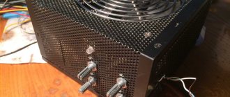
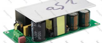
↑ Installation of LBP
The installation of the LBP is made in the form of separate units mounted in a housing from a computer power supply.
The power components of the circuit are mounted through insulating gaskets on a cooling aluminum plate mounted on one of the walls of the metal case. The rigid leads of the power elements form a fairly strong structure that supports a small perforated breadboard with a LBP control circuit mounted on it. The ET is mounted on the same wall of the case, increasing the total cooling area with the walls of its aluminum box (just in case). Controls, output sockets and indicators, made on the basis of dial indicators, are mounted on a getinax panel, thanks to which you can understand where and what is in the hut... The “ammeter” was calibrated in advance for other purposes and the resolution of the scale is twice as high as in reality. You have to divide all the readings by 2, which in principle is not difficult if you have a computer and a calculator.
Apart from the purchased adjustment knobs, there is nothing outstanding in the design of the LBP, as in the design of all my crafts, but even in this form the power supply helps me out almost every day.