Preface
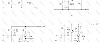
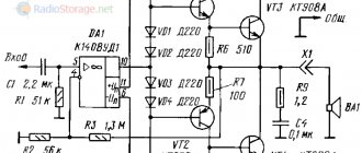
Okay, let's start from afar... As you know, all electronic devices consist of blocks. They are also often called cascades, modules, nodes, etc. In our article we will use the concept of “block”. For example, a power supply assembled according to this circuit:
consists of two blocks. I marked them in red and green rectangles.
In the red block we get constant voltage, and in the green block we stabilize it. That is, the block diagram will be like this:
The block diagram is a conditional division. In this example, we could even take a transformer as a separate unit that steps down an AC voltage from one rating to another. As it is more convenient for us, we divide our electronic trinket into blocks. The “from simple to complex” method completely works in our world. At the lowest level there are radio elements, at the highest there is a finished device, for example, a TV.
Okay, we got distracted. As you understand, any device consists of blocks that perform a specific function.
- Yeah! So what happens? Can I just stupidly take ready-made blocks and invent any electronic device that comes to my mind?
Yes! This is exactly what modern electronics is aimed at now. Microcontrollers and designers, such as Arduino, add even more flexibility to the creative endeavors of young inventors.
Everything sounds great on paper, but there are always pitfalls that need to be explored before you start designing electronic devices. Some of these pebbles are called input and output resistance .
I think everyone remembers what resistance is and what a resistor is. Although a resistor has resistance, it is active resistance. The inductor and capacitor will already have the so-called reactance. But what is input and output impedance ? This is already something new. If you listen to these phrases, then the input resistance is the resistance of some input, and the output resistance is the resistance of some output. Well, yes, everything is almost like that. And where can we find these input and output resistances ? But they are “hiding” in the radio-electronic device units themselves.
Input impedance
So, we have some block. As is customary all over the world, on the left is the input of the block, on the right is the output.
As expected, this block is used in some kind of radio-electronic device and performs some function. This means that some input voltage Uin will be supplied to its input from another block or from a power source, and voltage Uout will appear at its output (or will not appear if the block is the final one).
But since we apply voltage to the input (input voltage Uin), therefore, this block will consume some current Iin.
Now the most interesting thing... What does Iin depend on? In general, what does the current strength in a circuit depend on? Let's remember Ohm's law for a section of a circuit:
This means that our current strength depends on voltage and resistance. Let's assume that our voltage does not change, therefore, the current strength in the circuit will depend on... RESISTANCE. But where can we find it? And it hides in the cascade itself and is called input impedance .
That is, having disassembled such a block, we can find this resistor inside it? Of course not). It is a kind of resistance of radioelements connected according to the circuit of this block. Let's just say, total resistance.
Relationship between headphone impedance and amplifier output impedance
As you probably know, when headphones are connected to an amplifier, their frequency response changes due to the individual matching of the headphone impedance and the amplifier's output impedance. If the headphones and amplifier have a constant resistance over the entire frequency band, or the amplifier has zero resistance, then the frequency response does not change, but in all other cases changes are inevitable. If the amplifier has a constant output impedance, then the frequency balance will change in a similar way to the impedance curve of the headphones, and if the amplifier has an impedance close to zero and increases in the low frequency region, then the low frequencies of the headphones will be weakened.
Depending on the impedance values of the headphones and amplifier and their ratio, the changes can be either huge or barely noticeable. For high-impedance headphones, changes in the frequency response are minimal when connected to different amplifiers, just as amplifiers with low output impedance have little effect on the frequency response. In other words, the higher the ratio of headphone impedance to amplifier impedance, the less changes in frequency response.
A logical question is, what causes the frequency response of headphones to change? The fact is that the lower the ratio of the resistance of the headphones to the amplifier, the less voltage is supplied to the headphones (check in an on-line calculator), accordingly, if you set the level to, for example, 1 V without headphones, then when you connect headphones, the voltage value supplied to the headphones will decrease , and the more uneven the impedance of the headphones is, the more unevenly the frequency response will decrease; some frequencies will drop significantly, while others will not.
The user usually never knows how much voltage he applied to the headphones, and if the volume is insufficient, then the volume control corrects the situation. However, due to the fact that the frequencies initially decreased unevenly, increasing the volume returns their total level, but in a changed frequency response. The graph in the example shows that the low and mid frequencies sank more than the high ones.
The final graph, understandable to the consumer, takes the form where it is possible to evaluate not how much the frequencies drop, but how much their balance changes.
How to measure input impedance
As we know, each block is supplied with some kind of signal from the previous block, or it can even be powered from the network or battery. What can we do?
1) Measure the voltage Uin supplied to this unit
2) Measure the current Iin that our unit consumes
3) Using Ohm’s law, find the input resistance Rin.
If your input resistance is very high, in order to measure it as accurately as possible, use this circuit.
You and I know that if our input resistance is large, then the input current in the circuit will be very small (from Ohm’s law).
We denote the voltage drop across resistor R as UR
From all this we get...
When we make these measurements, keep in mind that the voltage at the generator output should not change!
So, let's calculate what kind of resistor we need to choose in order to measure this input resistance as accurately as possible. Let's assume that we have an input resistance Rin = 1 MegaOhm, and the resistor is R = 1 KiloOhm. Let the generator produce a constant voltage U=10 Volts. As a result, we get a circuit with two resistances. The voltage divider rule states: the sum of the voltage drops across all resistances in the circuit equals the emf of the generator.
The result is a circuit:
We calculate the current in the circuit in Amperes
It turns out that the voltage drop across the resistance R in Volts will be:
Roughly speaking 0.01 Volt. It is unlikely that you will be able to accurately measure such a small voltage on your Chinese multimeter.
What is the conclusion from this? To more accurately measure high input resistance, it is necessary to take an additional resistance of also a very large value. In this case, the shunt rule works: at a higher resistance, a larger voltage drops, and vice versa, at a lower resistance, a smaller voltage drops.
Measuring input impedance in practice
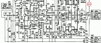
Well, that's it, the parking is over ;-). Let's now try in practice to measure the input impedance of a device. My gaze immediately fell on the Transistor Meter. So, we set the operating voltage of this transistor meter on the power supply, that is, 9 Volts, and when it is on, we measure the current consumption. How to measure the current in a circuit, read in this article. According to the diagram, it will all look like this:
But in reality it’s like this:
So, we got 22.5 milliamps.
Now, knowing the value of the current consumed, you can find the input resistance using this formula:
We get:
Output impedance
A clear example of output resistance is Ohm's law for a complete circuit, which has what is called "internal resistance". For those who are too lazy to read about this law, let’s briefly look at it here.
What did we have? We had a car battery that we used to light a halogen light bulb. Before connecting the light bulb, we measured the voltage at the battery terminals:
And as soon as we connected the light bulb, the voltage on the battery became less.
The voltage difference, that is, 0.3 Volts (12.09-11.79) fell on the so-called internal resistance r. This is also the OUTPUT RESISTANCE . It is also called source resistance or equivalent resistance .
All batteries have this internal resistance r, and it “clings” in series with the source of emf (E).
But is it only rechargeable batteries and various batteries that have output impedance? Not only. All power supplies have output impedance. This could be a power supply, a frequency generator, or even some kind of amplifier.
Thevenin’s theorem (in short, he was such a smart guy) said that any circuit that has two terminals and contains a bunch of different EMF sources and resistors of different values can be stupidly brought to an EMF source with some voltage value (Equivalent) and with some kind of internal resistance (Requivalent).
Eeq - equivalent source of emf
Req - equivalent resistance
That is, it turns out that if any voltage source powers the load, it means that the voltage source has an EMF and an equivalent resistance, which is also the output resistance .
E using a multimeter . Measuring the EMF seems to be clear, but how to measure Rout?
In principle, you can create a short circuit. That is, short-circuit the output terminals with a thick copper wire, through which the short-circuit current Is will flow.
As a result, we get a closed circuit with one resistor. From Ohm's law we find that
But there's a slight catch. Theoretically, the formula is correct. But in practice I would not recommend using this method. In this case, the current reaches an insane value, and in general, the entire circuit behaves inappropriately.
AudioKiller's site
The article was published in the magazine “Radio” No. 10 for 2007
Continuation of the topic: Amplifier with adjustable output impedance. Circuit, printed circuit board.
Download: Program for calculating combined environmental protection.
It is generally accepted that the output impedance of a power amplifier should be minimal, if possible zero. There is even such an amplifier parameter - the damping coefficient Kd, equal to the ratio of the load resistance to the output impedance of the amplifier. In some of them, this coefficient reaches tens and even hundreds, but it relates exclusively to the amplifier. If we consider the amplifier + loudspeaker system as a whole, the listener will not notice the difference in sound with CD = 100 and CD = 1000 of the power amplifier, since this does not take into account the resistance of the speaker wires and connector contacts, which in total is rarely less than 0.1 Ohm. If we also take into account the resistance of the speaker crossover filter, it becomes clear that, starting from a certain value, with increasing CD, there will be no increase in damping, and the sound as a whole will not change. Therefore, the desire to increase the specified coefficient above a reasonable limit at any cost is nothing more than a marketing ploy.
However, the output impedance does not have to be zero. Numerous publications, including in the magazine “Radio” [, ], prove the opposite: harmonic and intermodulation distortions of most dynamic loudspeakers decrease with increasing output impedance of the amplifier. This is one of the reasons for the popularity of tube amplifiers. Also, many note a subjective improvement in sound when using an amplifier with a high output impedance, which can improve the sound reproduction of even very mediocre speakers [3].
Therefore, the desire to reduce the output impedance of the UMZCH at any cost seems unjustified to the author; When designing any devices, you should look for the optimal combination of parameters and characteristics. The desire, first of all, to obtain impressive values for any one of them is more of an advertising nature, and often has a bad effect on the device as a whole.
The increased output impedance of the amplifier has a number of advantages:
- Reduced harmonic and intermodulation distortion in many low-cost drivers.
- Reducing the effect of thermal compression of loudspeaker heads.
- Improving the performance of UMZCH for a complex load, which is the AC.
- Reducing the influence of connecting wires and contacts on the sound of speakers.
In addition to the advantages, there are also some disadvantages:
- When the output impedance of the amplifier is comparable to the load impedance, due to filter mismatch, the total frequency response of a multi-band speaker usually worsens (more on this in the continuation: UMZCH with adjustable output impedance).
- All kinds of local resonances manifest themselves to a greater extent, for example, when sound is emitted by a diffuser in the zone mode.
- It is necessary to ensure a margin of output voltage of the UMZCH near the resonant frequency of the LF head [4].
- It is likely that “booming” will appear at the low frequencies due to an increase in the electrical quality factor of the loudspeaker at the main resonance frequency.
These disadvantages are not significant. The first of them is fundamentally absent in multiband amplifiers, the second has little effect if the output impedance is low, and allows, if necessary, to expand the area of joint operation in a multiband speaker. The third drawback is easy to take into account at the amplifier design stage.
Rice. 1.
It is interesting to note the influence of the output resistance on the unevenness of the frequency response of the speaker. When a voice coil moves in a magnetic field, an emf Evn is induced in it ( Fig. 1 ). Since the circuit is closed through the resistance of the voice coil and the output resistance of the amplifier, a current Idem arises in it. This current interacts with the magnetic field and a braking force appears, which dampens the moving system, counteracting the movement of the diffuser. Increasing the amplifier's output resistance reduces the damping current, making the diffuser move more freely, and as a result, the total frequency response changes. Whether this is good or bad depends on the total quality factor of the bass head, the optimal value of which is in the range of 0.6...0.8. With a lower quality factor, there is a decrease in the frequency response at lower frequencies, and with a higher quality factor, there is a rise in the frequency response, causing a “humbling” ( Fig. 2 ). The graphs in this figure are plotted for the “closed box” (CB) acoustic design. For a phase inverter or, for example, a bandpass resonator, the dependence of the frequency response on changes in the quality factor of the low-frequency head does not look so clear, since it is a function of a large number of variables, but the principle remains the same. Therefore, it makes sense to strive to increase the frequency response of speakers with a low-Q head, and such speakers are common among homemade designs. In addition, when designing an active speaker, it is useful to use control of the electrical quality factor of the head to optimize the frequency response in a box of a given volume [5].
Rice. 2.
Thus, it is not necessary that the output impedance of the amplifier should be zero. But it does not have to be infinitely large, as in the case of using a voltage-controlled current source. Usually the truth is somewhere nearby: for each amplifier + loudspeaker set there is an optimal value of the amplifier output impedance; you just need to define it.
Therefore, it is very convenient to be able to adjust the output impedance of the amplifier within a wide range; Usually, the output impedance is either very small in conventional amplifiers, or very high in PAs - ITUN. For this purpose, you can use combined - voltage and current - negative feedback. This solution has a number of important advantages:
- The required output impedance can be selected for any amplifier, regardless of its circuit design (industrial or homemade) after a little modification.
- The output impedance does not depend on the frequency response of the amplifier with an open feedback loop, since both feedback connections work simultaneously and jointly.
- The output impedance of the amplifier can take any reasonable value, allowing you to find the very optimum that gives the best sound quality. Typically, this optimum corresponds to a relatively low output resistance, approximately equal to the load resistance [6].
- Modification of the amplifier to increase the output impedance is available to radio amateurs of any qualification, which will allow them to become more familiar with this interesting side of the interaction of the UMZCH with the load.
It is interesting that when designing a high-quality acoustic system designed to operate from ITUN [], the actual output resistance acting in relation to the heads was 5...15 Ohms, and it was precisely this (small) resistance that was considered optimal!
Rice. 3.
The construction of combined OOS circuits for non-inverting and inverting amplifiers is shown in Fig. 3 . Here, resistor R1 forms an OOS voltage circuit (OOSN). Resistor R is a sensor of current flowing through the load resistance Rн. The voltage from resistor R, proportional to the load current, is supplied to the inverting input of the amplifier through resistor R2, providing current feedback (OCC). The output resistance Rout of the amplifier and its gain Ku depend on the ratio of the resistances of all these resistors. The resistance of resistor R should be as small as possible so as not to reduce the efficiency of the amplifier (increasing the output resistance using a combined OOS has almost no effect on the efficiency of the amplifier). Obviously, the value of Rout in any case cannot be less than the resistance R.
Thus, it is easy to obtain the required output impedance in any amplifier. To do this, it must be supplemented with resistors R and R2 with the required resistance. An example of the dependence of the gain Ku and the output resistance Rout of the amplifier on the OOC depth is shown in Fig. 4 for a non-inverting amplifier, and in Fig. 5 - for inverting.
Rice. 4.
Rice. 5.
It is interesting that for a non-inverting amplifier there is a ratio of the resistances of the resistors of the OOS circuits
Rн / R = R1 / Roc
at which Ku does not depend on the value of R2. This is convenient to use when modifying existing amplifiers. With a different resistance ratio, Ku may increase or decrease with increasing R2.
The calculation of the combined environmental impact is very labor-intensive, and to facilitate it, the following program is proposed:
combinOS
In English:
CombinOS engl
The program allows you to calculate the feedback circuits of both non-inverting and inverting amplifiers and performs three calculation options depending on the task.
Option 1. When modifying an existing amplifier with an OOCH circuit to obtain the required value of Rout, all elements of the OOCH circuit are assumed to be known. The resistance of the current sensor R is also set; it is selected based on allowable power dissipation. As a result of the calculation, we obtain the required resistance value R2 and the gain Ku obtained by introducing an additional OOST circuit.
Option 2. When designing an amplifier with a given Rout, the values of Ku, Rout are set and the required values of R1 and R2 are calculated.
Option 3. To estimate the parameters of an amplifier with a known circuit, the values of all elements of the OOS circuits are set and the values of Rout and Ku corresponding to such a circuit are calculated.
An example of a program window for calculating a non-inverting amplifier is shown in Fig. 6 .
Rice. 6.
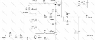
The property of a non-inverting amplifier to keep the gain constant when the OOC depth changes, and hence the output impedance, can be used to create amplifiers with an operationally adjustable output impedance. An example is given in [8] when the appropriate output impedance was selected to play music of a certain genre. This made it possible to achieve better (according to subjective assessment) sound quality. In Fig. Figure 7 shows a simplified diagram for introducing an output impedance regulator for the amplifier described in []. Three elements have been added to the circuit (see Fig. 7): resistors R21 and R22, which together form resistor R2 in Fig. 3, as well as a load current sensor - resistor R = Roc Rн / R1. Resistor R21 limits the range of adjustment of the output resistance to a maximum value of 8 Ohms (twice the load resistance) when the R22 slider is installed in the leftmost position in the diagram. The minimum output impedance of the amplifier is 0.6 Ohm. For linear regulation, the variable resistor must have a smoothly adjustable resistance near its minimum value. To do this, use a variable resistor of group B, if when rotating clockwise its resistance increases and the output resistance of the amplifier decreases, or group B, if when rotating clockwise its resistance decreases and the output resistance increases. For a stereo amplifier, dual resistors are used.
Rice. 7.
Using the proposed program, it is easy to calculate a similar regulator for any amplifier.
In addition, the program is supplemented by calculating the frequency response of a loudspeaker in a “closed box” acoustic design when connecting it to an amplifier with a non-zero output impedance ( Fig. 8 ). This calculation is especially relevant when designing subwoofers with low-Q heads (with a large stroke of the moving system). The example uses the parameters of the Peer less 830452 subwoofer head. The red line in Fig. 8 shows that even in a box of small volume (50 dm3) the lower operating frequency is 103 Hz (!) with a resonant frequency of the head of 19 Hz. With such a frequency response, it is simply impossible to classify this loudspeaker as a subwoofer. Reducing the volume of the box increases the quality factor Qtc of the speaker and reduces the lower frequency. But the efficiency of the subwoofer also decreases in proportion to the volume of the case (the program illustrates only the change in the frequency range and does not take into account the change in the efficiency of the speaker when correcting any parameters). It is clearly seen that the use of an amplifier with an output impedance of 6 Ohms allows us to obtain the lower limit of the frequency range in the same case, equal to 30 Hz!
Rice. 8.
It is important to note that the calculation of the frequency response module does not aim at a complete calculation of the speaker system. It is of an illustrative nature, making calculations using formulas “from a textbook”, and takes into account only three main parameters of the head and the volume of the loudspeaker cabinet, leaving out all other parameters, as well as such factors as filling the cabinet with sound-absorbing material or the occurrence of standing waves in the cabinet . Therefore, results are not a dogma, but a guide to action. As an example of action, we can recommend simulating the influence of the amplifier's output impedance on the frequency response of the speakers in the appropriate program (JBL SpeakerShop, LspCAD, LEAP, etc.). When modeling, the output impedance of the amplifier is added in the corresponding filter or simply added to the active resistance of the head.
When considering options for optimizing the frequency response of a subwoofer, it is necessary to mention the so-called Linkwitz corrector [10] - a special circuit that corrects the frequency response and phase response of the (pre) amplifier so that the resulting total frequency response of the amplifier + subwoofer system is horizontal down to very low frequencies. The corrector allows you to achieve the same effect of expanding the frequency range without increasing the output impedance of the amplifier. However, in the author’s opinion, it is more optimal to increase the output impedance, since in this case the acoustic parameters of the subwoofer are corrected. In addition, the increased output impedance reduces thermal compression and the effect of voice coil inductance nonlinearity on sound quality.
Thus, this method of correction seems optimal. First, by selecting the appropriate output impedance of the amplifier, the best set of acoustic parameters is ensured, and then the resulting characteristic is brought to the desired one through equalization, for example, with a Linkwitz corrector. This conclusion was confirmed experimentally - the combination of the optimal output impedance of an amplifier with a Linkwitz corrector and a low-Q speaker was clearly found to be the best (in a blind test) in comparison with using the corrector alone; in both cases the frequency response of the loudspeaker was the same. It is noteworthy that in the calculation of the Linkwitz corrector [11] it is possible to set the output impedance of the amplifier and thereby select a truly optimal correction.
It remains to add that increased output impedance is not an end in itself, and it should be used only where it will undoubtedly be beneficial.
And finally, briefly about the gain Ku produced by the program. Strictly speaking, its value depends on the load resistance. To avoid numerous “ifs” and “whys”, the Ku value is calculated as the ratio of the load voltage (specified in the resistance program Rн) to the input voltage.
In addition to its undoubted advantages, the program also has a disadvantage: the calculation is performed for the active resistance of the load (its impedance module is entered into the program). With the reactive nature of the load, the actual output impedance of the amplifier is 5...15% less than calculated if the phase shift reaches 30 degrees.
The program allows you to save the results obtained in text (elements of OOS circuits and loudspeaker parameters) and graphic (amplifier circuit and frequency response graphs) formats.
LITERATURE
1. Ageev S. Should the UMZCH have a low output resistance? - Radio, 1997, No. 4, p. 14 ? 16.
2. Aleinikov A., Syritso A. Improving sound reproduction in the UMZCH - loudspeaker system. - Radio, 2000, No. 7, p. 16 ? 18.
3. Alekseev R. AS “Sven HP-830 B” with two-way UMZCH. - Radio, 2007, No. 1, p. 15, 16.
4. Syritso A. Features of UMZCH with high output impedance. - Radio, 2002, No. 2, p. 16, 17.
5. Vinogradova E. L. Design of loudspeakers with smoothed frequency characteristics. - M.: Energy, 1978.
6. Sokolov A. From amplifier to loudspeaker. - Radio, 1997, No. 7, p. 20, 21, 49.
7. Father S. Current amplifier through the eyes of an engineer.
8. Maslov A. UMZCH with adjustable output resistance. - Radio, 2002, No. 12, p. 18.
9. Hi-Fi amplifier based on TDA7294 chip.
10. About subwoofers, deep bass and the Linkwitz corrector.
11. “Professional” calculation of the Linkwitz corrector.
16.09.2007 — 26.05.2008
Total Page Visits: 2993 — Today Page Visits: 3
Measuring output resistance in practice
There is another, safer way. I won’t repeat myself, I’ll just copy Ohm’s law from the article for a complete circuit, where we found the internal resistance of the battery. In that article, we connected a halogen light bulb to the battery, which was a load R. As a result, an electric current flowed through the circuit. The voltage dropped across the light bulb and the internal resistance, the sum of which was equal to the EMF.
So, first we measure the voltage on the battery without a light bulb.
Since in this case the circuit is open (there is no external load), therefore the current in circuit I is equal to zero. This means that the voltage drop across the internal resistor Ur will also be zero. As a result, we are left with only the EMF source, from which we measure the voltage. In our case, E=12.09 Volts.
As soon as we connected the load, the voltage immediately dropped across the internal resistor and the load, in this case the light bulb:
Now at the load (on a halogen lamp) the voltage drops UR = 11.79 Volts, therefore, the voltage drop across the internal resistor is Ur = E-UR = 12.09-11.79 = 0.3 Volts. The current strength in the circuit is equal to I = 4.35 Amperes. As I already said, our EMF is equal to E = 12.09 Volts. Therefore, from Ohm’s law for a complete circuit, we calculate what our internal resistance r will be equal to:
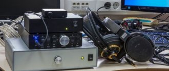
Examples of typical amplifiers with characteristic output impedance graphs
Amplifiers with a flat output impedance can be classified as (based on measurements in the personalaudio laboratory)
ESI/Audiotrak Dr. DAC prime (review) Asus Xonar Essence ST (review) Asus Xonar Essence One (report) E-MU 0204 USB (review) Creative SoundBlaster Z (review)
The category of not only equal output resistance, but close to zero can include
iBasso DX 100 (review)
The category of close to zero and increase in the low frequency region includes
Colorful ColorFly C4 PRO (review) Cowon C2 (review) The reports for each headphone provide an analysis of the interaction of the headphones with amplifiers of all main types - with a constant output impedance and zero with a rise in the low frequencies.