LF amplifier, the circuit of which is shown in Fig. 1, despite its simplicity, is designed for high-quality amplification of speech and music programs.
During its development, recommendations were taken into account that ensure low dynamic signal distortion and low noise levels in the speakers: negative current feedback (NFC), which improves the symmetry of the amplifier output stage drive. In table 1 shows the technical parameters of the amplifier.
Rice. 1. Schematic diagram of a simple amplifier using transistors and an op-amp.
Table 1. Technical parameters of the amplifier.
| Output power at 4 Ohm load, W | 60 |
| Output power at 8 Ohm load, W | 30 |
| Reproducible frequency range, Hz | 10…30000 |
| SOI, no more, % | 0,1 |
| Nominal input voltage, mV | 700 |
| Input impedance, com | 50 |
| Output resistance, Ohm | 0,04 |
| Relative noise level, dB | -95 |
The voltage amplifier is assembled on a high-voltage op-amp KR1408UD1 (DA1), the pre-terminal stage is on transistors KT972A (VT1) and KT973A (VT2), and the final current amplifier is on transistors KT908A (VT3, VT4).
To eliminate the possibility of self-excitation, it was necessary to abandon the use of composite transistors consisting of three transistors (the so-called “triples”) in the final stage.
However, this required the selection of output transistors VTZ and VT4 according to the static current transfer coefficient, which in this case should be at least 25.
The quiescent current of the output transistors is 20...30 mA, as mentioned above, stabilizes with a change in temperature VD1...VD4, which are in contact with heat sinks VT3 and VT4. The functions of the bass reflex are performed by a cascade based on transistor VT2. Gain of the entire device:
To eliminate step-type distortions, a small bias voltage is applied to the bases VT1 and VT2, created through a chain of diodes VD1 ... VD4. Circuit R9C4 prevents self-excitation of the amplifier at higher audio frequencies and when the load is turned off. For the same purpose, capacitors C2 and C3 are installed, which must be placed near the DA1 chip.
UMZCH RF technology for self-assembly of a tube amplifier
Most audio lovers are quite categorical and are not ready to compromise when choosing equipment, rightly believing that the perceived sound must be clear, strong and impressive. How to achieve this?
UMZCH RF technology for self-assembly of a tube amplifier
Perhaps the main role in resolving this issue will be played by the choice of amplifier. The Amplifier function is responsible for the quality and power of sound reproduction. At the same time, when purchasing, you should pay attention to the following designations, which mark the introduction of high technologies in the production of audio equipment:
- Hi-fi. Provides maximum purity and accuracy of sound, freeing it from extraneous noise and distortion.
- Hi-end. The choice of a perfectionist who is willing to pay a lot for the pleasure of discerning the smallest nuances of his favorite musical compositions. Hand-assembled equipment is often included in this category.
Specifications you should pay attention to:
- Input and output power. The rated output power is of decisive importance, because edge values are often unreliable.
- Frequency range. Varies from 20 to 20000 Hz.
- Nonlinear distortion factor. Everything is simple here - the less the better. The ideal value, according to experts, is 0.1%.
- Signal to noise ratio. Modern technology assumes a value of this indicator over 100 dB, which minimizes extraneous noise when listening.
- Dumping factor. Reflects the output impedance of the amplifier in its relation to the nominal load impedance. In other words, a sufficient damping factor (more than 100) reduces the occurrence of unnecessary vibrations of equipment, etc.
It should be remembered: the manufacture of high-quality amplifiers is a labor-intensive and high-tech process; accordingly, too low a price with decent characteristics should alert you.
Classification
To understand the variety of market offers, it is necessary to distinguish the product according to various criteria. Amplifiers can be classified:
- By power. Preliminary is a kind of intermediate link between the sound source and the final power amplifier. The power amplifier, in turn, is responsible for the strength and volume of the output signal. Together they form a complete amplifier.
- Based on the element base, there are tube, transistor and integrated minds. The latter arose with the goal of combining the advantages and minimizing the disadvantages of the first two, for example, the sound quality of tube amplifiers and the compactness of transistor amplifiers.
- Based on their operating mode, amplifiers are divided into classes. The main classes are A, B, AB. If Class A amplifiers use a lot of power, but produce high-quality sound, Class B amplifiers are exactly the opposite, Class AB seems to be the optimal choice, representing a compromise between signal quality and fairly high efficiency. There are also classes C, D, H and G, which arose with the use of digital technologies. There are also single-cycle and push-pull operating modes of the output stage.
- Depending on the number of channels, amplifiers can be single-, double- and multi-channel. The latter are actively used in home theaters to create volumetric and realistic sound. Most often there are two-channel ones for right and left audio systems, respectively.
Attention: studying the technical components of the purchase is, of course, necessary, but often the decisive factor is simply listening to the equipment according to the principle of whether it sounds or not.
Application
The choice of amplifier is largely justified by the purposes for which it is purchased. We list the main areas of use of audio amplifiers:
- As part of a home audio system. Obviously, the best choice is a tube two-channel single-cycle in class A, and the optimal choice can be a three-channel class AB, where one channel is designated for the subwoofer, with the Hi-fi function.
- For car audio system. The most popular are four-channel AB or D class amplifiers, depending on the financial capabilities of the buyer. Cars also require a crossover function for smooth frequency control, allowing frequencies in the high or low range to be cut as needed.
- In concert equipment. The quality and capabilities of professional equipment are reasonably subject to higher demands due to the large propagation space of sound signals, as well as the high need for intensity and duration of use. Thus, it is recommended to purchase an amplifier of at least class D, capable of operating almost at the limit of its power (70-80% of the declared one), preferably in a housing made of high-tech materials that protects from negative weather conditions and mechanical influences.
- In studio equipment. All of the above is also true for studio equipment. We can add about the largest frequency reproduction range - from 10 Hz to 100 kHz in comparison with that from 20 Hz to 20 kHz in a household amplifier. Also noteworthy is the ability to separately adjust the volume on different channels.
Thus, in order to enjoy clear and high-quality sound for a long time, it is advisable to study in advance all the variety of offers and select the audio equipment option that best suits your needs.
Schemes of homemade UMZCH
ULF Transistor AmplifiersSetting up the UMZCH comes down to setting the quiescent current. It is set by trimming resistor R15. First, set the minimum quiescent current and let the amplifier run for 15-20 minutes at medium power. After this, the input is short-circuited, the acoustics are turned off and the quiescent current is set within 50-80 mA. It is measured by the voltage drop across resistors R24 - R27, it should lie in the range of 0.22-0.36 V. The voltage in the right and left shoulders may differ slightly. In the circuit, it is advisable to use film capacitors K73-17 or imported analogues, C8, C12, C13 - ceramics can be used. It is advisable to select output and pre-output transistors in pairs, at least from one batch.
Scheme of a high-quality UMZCH using op-amps and transistors
Its main features are the use of op-amps in small-signal mode, which expands the frequency band of signals reproduced without exceeding the slew rate of the op-amp's output voltage; the use of output stage transistors in a circuit with an OE, and a pre-final stage with a divided load in emitter and collector circuits. The latter, in addition to the obvious design advantage - the possibility of placing all four transistors on a common heat sink, provides certain advantages compared to the output stage in which the transistors are connected according to the OK circuit. Main technical characteristics of UMZCH: Nominal frequency range …………………………… Hz 20…20000 Nominal (maximum) output power, W, at a resistive load, 4 Ohms: …………………………… ……. 30(42) Harmonic coefficient at rated power, %, no more, in the rated frequency range ……………………………………………………….0.01 Rated (maximum) input voltage, V ………… 0.8(1) Input resistance, kOhm ……………………………………………………….. 47 Output resistance, Ohm, no more than …………………………. 0.03 Relative noise and background level, dB, no more than …………… -86 Op-amp DA1 is powered through transistors VT1, VT2, which reduce the supply voltage to the required values. The quiescent currents of the transistors create voltage drops across resistors R8 and R9, sufficient to provide the required bias voltage at the bases of transistors VT3, VT4 and VT5, VT6. In this case, the bias voltages for the transistors of the final stage are chosen such (0.35...0.4 V) that they remain reliably closed when the supply voltage increases by 10...15% and overheating by 60...80°C. The bias voltages are removed from resistors R12, R13, which simultaneously stabilize the operating mode of the transistors of the pre-final stage and create local negative feedback on the current. Low-pass filter R3C2 and high-pass filter C3R10 with cutoff frequencies in the region of 60 kHz prevent the operation of relatively low-frequency transistors VT3 - VT6 at higher frequencies in order to avoid their breakdown. Capacitors C4, C5 correct the frequency response of the pre-terminal and final cascades, preventing their self-excitation if installation is unsuccessful. Coil L1 increases the stability of the UMZCH with a significant capacitive load. The UMZCH is powered by an unstabilized rectifier. It can be common to both channels of the stereo amplifier, but in this case the capacitance of filter capacitors C8 and C9 must be doubled, and the diameter of the wire of the secondary winding of transformer T1 must be doubled. Fuses are included in the power supply circuit of each amplifier. In addition to what is indicated in the diagram, the UMZCH can use op-amps K140UD6B, K140UD7A, K544UD1A, however, the harmonic coefficient at frequencies above 5 kHz will increase in this case to approximately 0.3%. The installation of the UMZCH and the connection of its channels to the power source are of great importance. The power wires (+22 V, -22 V and common) should be as short as possible (they should be laid separately for each channel) and of a sufficiently large cross-section (with a maximum power of 42 W - at least 1.5 sq. mm). Wires of the same cross-section must be used to connect the speaker systems, as well as the emitter and collector circuits of the final stage transistors to the UMZCH board.
UMZCH circuit on transistors
The first stage of the power amplifier is assembled using op amp A1. The input signal is fed to the inverting input of the op-amp through a high-pass filter (HPF) R1C1R3 with a cutoff frequency of 20 kHz. In order for this high-pass filter parameter not to change significantly, the output impedance of the pre-amplifier should be no more than 200 Ohms. It must be connected to the input of the power amplifier through an electrolytic capacitor with a capacity of 10 μF. The next stage is a push-pull cascade (OE - OB) amplifier with a cutoff frequency of 4.7 MHz on transistors V6, V5 and V7, V4. It performs the functions of a phase inverter and a generator of stable bias currents for transistors of the sub-end stage. The latter is made on transistors of different structures V8, V9 and is covered by local OOS in terms of current (resistors R12, R13 in the emitter circuits). The thermal stabilizing effect of these OOS, together with the supply of the base circuits of transistors V8, V9 with stable bias currents, determines the high temperature stability of the amplifier as a whole. The quiescent current of transistors V8, V9 is about 30 mA (at +60°C it increases to 50 mA.) The cutoff frequency of this stage is 130 kHz. The output stage (V10, V11) is an emitter follower with a cutoff frequency of about 1402 kHz. Since the transistors of this stage, as already mentioned, operate without an initial bias, to reduce the “step” type distortions inevitable in mode B, resistor R14 was introduced, which at low signal levels (when transistors V10, V11 are closed) connects the load to the output of the linear pre-final stage .
The amplifier can be powered from any bipolar rectifier with a capacitive filter, providing an output voltage of +-30 V at a load current of 1 A. The amplifier can use the K140UD1B op-amp with a voltage gain of at least 2000. The transistors of the cascade amplifier may be different from those indicated in the diagram , types, but always with a maximum permissible emitter-collector voltage of at least 30 V and a cutoff frequency of at least 40 MHz (in particular, instead of GT321A transistors, you can use KT626 silicon transistors with indices A, B and C). To improve the symmetry of the amplifier arms, it is advisable to replace the germanium transistors in the pre-final and final stages with silicon ones: instead of GT905A, install KT814G, and instead of GT806V, install KT816G.
Simple UMZCH for 50 watts
Output power at a load with a resistance of 4 Ohms, W: …… 60 Gain, dB ……………………………………………………………………. 26 Input voltage, V …………………………………………………….. 0.75 Input resistance, kOhm …………………………………………………………… ……. 10 Slew rate of output voltage, V/µs, not less than .. 12 Nonlinear distortion coefficient, %, not more than,………… 0.17 Relative background level, dB……………………………………………………… …. -80 Relative internal noise level, dB, no worse than ..... -86 The circuit diagram of the amplifier does not have any features and is not discussed in detail. Instead of the K140UD8A op-amp, the amplifier can use an op-amp of the same type with any index, as well as K574UD1 and K544UD2. The KS515A zener diodes can be replaced with two D814A zener diodes connected in series.
If you liked the diagram - like it!
SCHEMATIC DIAGRAMS OF ULF
See more amplifier circuits
VALUES AMPLIFIERS TRANSISTOR AMPLIFIERS
AMPLIFIERS ON CHIPS ARTICLES ABOUT AMPLIFIERS
[/td]
Tube ULF
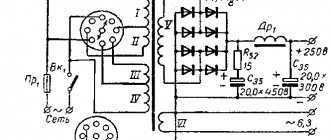
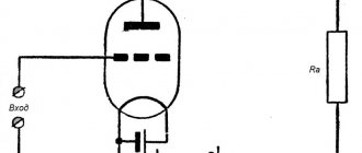
Tube audio amplifier for 6S2P, 6P18P (12W)
Good afternoon, dear radio amateurs. As you know, history develops in a spiral, and the history of the development of audio technology is no exception to this. If you look at the playback amplifier market, you will notice that in the last few years there has been a reincarnation of tube amplifiers, and some manufacturers have resumed production of radio tubes. Today we would like to offer you the design of a simple tube amplifier designed...
2 960 0
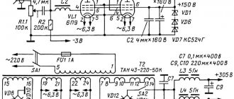
Single-stage tube UMZCH 4W (6P9), diagram and description
The article describes the design of a single-stage low-power tube UMZCH, used by the author in conjunction with speakers built on the basis of high-sensitivity broadband heads. The amplifier uses parallel connection of two 6P9 pentodes, characterized by high gain. This made it possible to obtain an output power of up to 4 W when working with a signal source providing a signal voltage of up to 1.5...2 V, i.e. from any CD player or smartphone...
1 906 0
Home tube vinyl corrector (EF86, 6N2P)
This article is intended for vinyl lovers who have at least basic knowledge of radio engineering and know how to hold a soldering iron in their hands. Despite the abundance of digital audio sources, many of us still have a large collection of vinyl records. Moreover, the sound quality is decent for the recorded...
1 868 0
Tube amplifier with transformers TPP-258-127/220-50 (6N8S and 6P3S)
Schematic diagram of a homemade tube power amplifier for 6N8S and 6P3S, which uses factory transformers of the TPP-258-127/220-50 type. The author tells how he made the amplifier and what changes he made to the UMZCH circuit; photos of the disassembled and finished device are also provided.
1 2354 0
Circuit of a push-pull tube power amplifier for 6P14P (8 Watt)
The push-pull output stage of the stereo amplifier is distinguished by the use of a common current generator on the microcircuit in the cathode circuit, thanks to which paraphase control of the 6P14P pentodes is ensured. By choosing the load resistance transformation ratio you can change to some extent...
2 2866 13
Simple tube power amplifier for 14-20 Watts (6N2P, 6P14P)
The AF power amplifier, the circuit of which is shown in the figure, is made using lamps from old black-and-white TVs or radios. This is a pre-amplifier with a bass reflex on a 6N2P double triode and a push-pull output stage on two 6P14P tubes. The use of such old components is often...
8 2773 10
Tube-transistor ULF for headphones and speakers (6N23P)
To all connoisseurs of tube sound, I present to you my design of a tube semiconductor amplifier. The source for creativity was the deposits of germanium transistors that had been lying in a box and successfully forgotten for a good ten years. Probably few people know the fact that it is germanium that gives the sound as close as possible to tube sound...
4 4593 24
Circuit diagram of a tube ULF with a five-band equalizer (6N3P, 6P14P, 6P45S)
I propose a well-developed UHF circuit for 6p45s, with a five-band tone block. The amplifier is made according to a classic single-ended circuit. The circuit of A. Manakov was taken as the basis. The diagram does not need a description of the operation. During the assembly and commissioning process, some resistor values were changed. In the process…
3 4438 0
High-quality tube headphone amplifier for 6N1P, 6N23P
How the idea to build a tube headphone amplifier came about The idea of building a high-quality tube headphone amplifier has been in my head for a long time. The idea is not bad, but one thing stopped me. From the technical side, assembling this product was not difficult. A lot of things have been reviewed...
4 4781 6
Tube ULF with parallel connection of lamps (6N3P, 6P14P)
I bring to your attention a well-reproducible, proven, tube ULF circuit with parallel connection of lamps, based on an entry-level ULF. I once became interested in the circuit of an entry-level tube ULF. I repeated it and was pleased with the result.
9 4493 4
AMPLIFIER FOR SUBWOOFER ACCORDING TO LANZAR CIRCUIT
Well, what can we say about one of the most repeated power amplifier circuits - the Lanzar circuit was developed back in the 70s of the last century. On a modern high-precision elementary base, Lanzar began to sound even better. In theory, the circuit is excellent for wideband acoustics; distortion at half volume is only 0.04% - full-fledged Hi-Fi .
The output stage of the amplifier is built on a pair of 2SA1943 and 2SC5200, all stages are assembled on complementary pairs that are as close as possible in parameters, the amplifier is built entirely on a symmetrical basis. The rated output power of the amplifier is 230-280 watts, but much more can be removed by increasing the input supply voltage.
The values of the limiting resistors of the differential stages are selected based on the input voltage. Below is the table.
Power supply ±70 V - 3.3 kOhm...3.9 kOhm Power supply ±60 V - 2.7 kOhm...3.3 kOhm Power supply ±50 V - 2.2 kOhm...2.7 kOhm Power supply ±40 V - 1.5 kOhm...2.2 kOhm Power supply ±30 V - 1.0 kOhm...1.5 kOhm
These resistors are selected with a power of 1-2 watts; during operation, heat generation may be observed on them.
The regulating transistor was replaced with a domestic KT815; at that time there was no other one at hand. It is designed to regulate the quiescent current of the output stages; it does not overheat during operation, but is mounted on a common heat sink with the transistors of the output stage.
It is advisable to do the first start of the circuit from the mains power supply; connect a 100-150 watt incandescent lamp in series with the mains winding of the transformer; if there are problems, then burn a minimum of parts. In general, Lanzar’s circuit is not critical to the installation and components; I tried it even with a wide range of components used, using domestic radio components - the circuit shows high parameters even in this case. Lanzar's circuit diagram has two main versions - on bipolar transistors and using field switches in the penultimate stage, in my case the first version.
The second pre-output stage operates in pure class “ A ”, so during operation the transistors overheat. Transistors of this cascade must be installed on a heat sink, preferably a common one, do not forget about insulation - mica plates and insulating washers for screws.
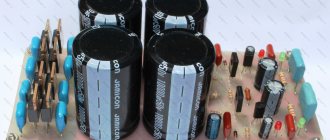
A correctly assembled circuit starts up without any problems. We make the first launch with the INPUT SHORT-CORTED TO GROUND, i.e. The amplifier input is connected to the middle point from the power supply. If nothing explodes after launch, then you can disconnect the input from the ground. Next we connect the load - the speaker and turn on the amplifier. To make sure the amplifier is working, just touch the bare input wire. If a peculiar roar appears in the head, then the amplifier is working! Next, you can strengthen all the power parts with heat sinks and send an audio signal to the amplifier input. After 15-20 minutes of operation at 30-50% of the maximum volume, you need to adjust the quiescent current. The photo shows everything in detail; it is advisable to use a digital multimeter as a voltage indicator.
Amplifier output power measurement
How to set the quiescent current
Radio circuits. — Tube amplifier circuits
Despite the fact that we live in an age of high technology, tube sound amplifiers rightfully occupy an honorable place among lovers of high-quality sound, and in this section you will find amplifier circuits made with tubes.
You can easily make many of these tube amplifiers yourself, and if you suddenly have any questions about assembly, adjustment or repair, then come to our FORUM and we’ll think about it together.
Materials in this category
Amplifier using 6N2P and 6P43PU tubes Amplifier using tubes from an old TV Amplifier using tubes and germanium transistors Tube ULF circuit with a five-band equalizer (6N3P, 6P14P, 6P45S) Hybrid amplifier - tubes and transistors 10 W tube ULF (6ZH3P, 6N1P, 6P 14P) Tube ULF 5 Watt ( 6N2P, 6P14P)Powerful tube amplifier for 6N1P, 6N6P, 6RZS (100W, 8 Ohm)Rigond tube ULF radios for 6N2P and 6P14PLMiniya tube ULF radios for 6N2P and 6P14PSAmplifier circuit for 6N2P, 6N1P, 6P14P , 6E1P (tape recorder Astra-2) Scheme three-way tube amplifier on 6N1P, 6P14PD two-channel tube amplifier by B. Jaunzems on 6N2P, 6P14P (2W + 4W) Circuit diagram of a two-channel UMZCH on tubes 6N2P, 6P14P (30 W) Amplifier circuit on tubes 5Zh2p, 6N3P, 6P14P by Yu. Romanyuk (6V) t+2x2W) Two-channel amplifier on tubes 6N2P, 6P14P by A. Mezherovsky (8 W) Two-channel tube amplifier 24 W (6Zh32P, 6N2P, 6P14P) G. Karaseva Two-channel tube ULF 4 W (6Zh1P, 6N9S, 6N5S) by A. Slonim Bridge tube amplifier 20 Watt (6N1P, 6P41S) K. WeisbeinaTube amplifier 65 Watt (6Zh1P, 6N2P, 6N1P, GU-50) A. BaevaSimple tube amplifier 2-3 W on 6N2P, 6P43PStereophonic tube amplifier 2x10 W (6Zh1P, 6N2P, 6N1P, 6P14P) I. StepinaTube amplifier 6N9S, 6N8S, 6P3S (35W) Tube amplifier for 6N2P, 6P3S, 6E5S (30-60W) High-quality tube amplifier (6N1P, 6P14P)N. Zykova Stationary tube amplifier on 6Zh1P, 6N2P, 6P14P G. Gendin Tube amplifier on 6N2P and 4x 6p14PS Amplifier circuit 10 W on tubes 6N2P, 6P14P (S. Matvienko) ULF 8 W on tubes 6N1P, 6N2P, 6P1P (A. Kuz menko) Tube ULF 6 W on 6N2P 6P14P (Yu. Mikhailov) Lamp UNCh 4 W at 6ZH1P, 6P15P (Krylov) Stereoonon Lamp UNF 6N1P, 6N2P, 6C4C, 5C3S-lamp amplifier without an output transformer (L. Kononovich) Zu-430-sterephonic amplifier for five for five lampsUnusual transformer for tube ULFUMZCH on octal pentodes