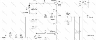
Setting the quiescent current of the amplifier Radiotekhnika U-101
Setting the quiescent current of the output transistors of the Radiotekhnika U-101 amplifier is usually performed after repairing the ULF-50-8 boards, or for preventive purposes.
You may ask, how will the sound change if the quiescent current is set lower or higher than the recommended value? It's very simple, a quiescent current below the recommended value will lead to distortion of the output signal at a relatively low volume level. An excessive current will lead to excessive heating of the transistors and radiator at low volumes, but the sound will be without audible distortion.
What value of the quiescent current is the norm for the Radiotekhnika U-101 amplifier? According to the repair instructions for this amplifier, the quiescent current must be set within 40-50mA.
Amplifier run
The run is performed after repairing the device and before setting it up. You need to submit a music program to one of the inputs (for example, “Univ.”) and drive the amplifier at a medium volume level for at least an hour.
Quiescent current setting process
This method is simple and taken from the repair instructions for the Radiotekhnika U-101 amplifier (). There are other methods, but I will not consider them in this article.
So, after running our device, it needs to be disconnected from the network. Next, find the power wire “+Upit.out.” and connect a DC milliammeter into its gap.
The input signal from the amplifier must be turned off, the volume knob turned to minimum.
Then turn on the amplifier and the tester display will display the quiescent current
Initially, on one channel the value was 94mA, and on the other 122mA.
Its installation is carried out by rotating the engine of the trimming resistor R12. Attention! I strongly recommend making adjustments with resistor R12 when the amplifier is turned off. The resistor is old, its electrically conductive layer and slider can oxidize over a long time. As a result of this, when the R12 engine rotates, its resistance may be infinite for some time, and the transistors will fail. Be careful!
The adjustment must be done very smoothly, using a dielectric screwdriver. After adjustment, connect the power and look at the readings on the multimeter display. If the quiescent current is not set within 40-50mA, then turn off the power to the amplifier and make further adjustments.
The indicator strongly depends on temperature, therefore, having set the required current, the amplifier must be driven again and a control adjustment must be performed. For example, by setting the current of both channels to about 45 mA, after the radiators cooled down, the current was already approximately 30 mA.
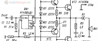
Amplifier circuit Radiotekhnika U-101
Final assembly of the transformer.
I glued the halves of the magnetic circuit together with epoxy resin and finally assembled the transformer only after the ULF was completely assembled and tested.
If you do not glue the halves of the magnetic circuit together, the transformer will most likely hum. It may hum quieter or louder, but it will be audible.
If you have to break the gluing area, for example, in order to lengthen or shorten the winding, then some plates of the armor core may peel off from the impact. If this happens, it will be very difficult to completely get rid of the buzzing. Therefore, it is better to do gluing at the very end.
To complete the assembly of the transformer, you can wind a layer of electrical cardboard or paper 0.1 mm thick over the coil. It is useful to put data on the windings on paper. If you also wrap a layer of glass or varnish fabric over the paper, the transformer will take on an industrial look.
Setup.
During commissioning, only one error had to be corrected. This error manifested itself in the form of a small hum in the speakers and was caused by incorrect ground wiring on the power supply board.
The hum appeared due to the fact that a tiny ripple voltage penetrated the input of the voltage stabilizer, and from there into the pre-amplifier.
On the original version of the printed circuit board, the leads of the secondary windings of the transformer going to the case were connected together, which is not correct, since all power grounds should be connected at one point, and not at two.
Initial version of the printed circuit board.
And this is already a modified version. During modification, we had to cut one track, item 1, and add one contact, item 2, to connect the transformer winding that powers the voltage stabilizer.
In addition, another defect has surfaced in the ULF, which has not yet been eliminated. These are clicks when the ULF is turned on and off. The source of the clicks is the volume and tone control unit.
The picture shows a diagram taken at the output of the tone control block. The startup and shutdown of the microcircuit itself occurs very smoothly. Both voltage and sound volume increase within a couple of seconds. But there is a small step in the voltage rise and fall curve, which seems to be caused by some transient processes in the microcircuit. This difference hits the input of the terminals and causes clicks.
I still doubt that Philips has developed such a crooked chip and I blame the specific manufacturer NXP Semiconductors or the batch of chips. First, I’ll try to look for a similar microcircuit from another manufacturer on our radio market.
As I already wrote, an amplifier powered by a bipolar source does not create clicks when turned on and off.
I wouldn’t want to install a loudspeaker shutdown circuit for an amplifier that doesn’t need it.
So, if someone is going to use the TDA1524A, they should pay attention to this circumstance.
Otherwise, the assembly went without any complications.
Measurements.
Ambient temperature – 20ºС.
Mains voltage – 220V.
Sine wave signal – hardware low-frequency generator.
Music cue – Carlos Santana “Jingo: The Santana Collection”.
Load – equivalent to 2x4 ohm load.
An oscillogram taken on a ULF load when connected to the input of a low-frequency generator.
Effective power limited by supply voltage ripples – 2x9 Watts.
An oscillogram taken at a load when a music signal is connected to the input.
Peak musical power – 2x18 watts.
Radiator temperature during continuous operation at maximum power, at a frequency of 1 kHz, in power limit mode – 75ºС
The radiator temperature during prolonged music playback at maximum volume limited by supply voltage ripples is 65ºС.
Classification of output stages
There are several methods for assembling the output stage:
- From transistors having different conductivities. For these purposes, “complementary” (close in parameters) transistors are most often used.
- Of transistors having the same conductivity.
- From transistors of a composite type.
- From field effect transistors.
The operation of an amplifier designed using complementary transistors is simple: the positive signal half-wave triggers the operation of one transistor, and the negative half-wave triggers the operation of the other. It is necessary that the arms (transistors) operate in the same modes, and to implement this, a base bias is used.
If the amplifier uses the same transistors in operation, then this does not have any fundamental differences from the first option. Except for the fact that for such transistors the signal should not be different.
When working with other types of amplifiers, you must remember that the voltage is negative for pnp transistors, and positive for npn transistors.
Usually the title of power amplifier belongs to the final stage, since it operates with the largest values, although from a technical point of view the preliminary stages can also be called this way. The main indicators of an amplifier include: useful power delivered to the load, efficiency, amplified frequency band, and nonlinear distortion factor. These indicators are greatly influenced by the output characteristics of the transistor. When creating a voltage amplifier, single-ended and push-pull circuits can be used. In the first case, the amplifier operating mode is linear (class A). This situation is characterized by the fact that the flow of current through the transistor continues until the period of the input signal ends.
A single-ended amplifier has high linearity. However, these qualities can be distorted when the core is magnetized. To prevent such a situation, it is necessary to take care of the presence of a transformer circuit with a high level of inductance for the primary circuit. This will affect the size of the transformer. In addition, due to the principle of its operation, it has a fairly low efficiency.
In comparison, the data for a push-pull amplifier (class B) is much higher. This mode allows you to distort the shape of the transistor current at the output. This increases the result of the ratio of alternating and direct currents, while reducing the level of power consumption; this is considered the most important advantage of using push-pull amplifiers. Their operation is ensured by the supply of two equal in value, but phase-opposite voltages. If there is no transformer with a midpoint, then you can use a phase-inverted cascade, which will remove voltages opposite in phase from the corresponding resistors of the collector and emitter circuits.
There is a push-pull circuit that does not include an output transformer. This will require different types of transistors that work as emitter followers. If a bipolar input signal is applied, the transistors will alternately open and the currents will diverge in opposite directions.
Replacing transistors
Since ULF (low-frequency amplifiers) are becoming more and more popular, it would be a good idea to know what to do if such a device fails.
If the output transistor gets hot, there is a high probability that it is broken or burned out. In such a situation it is necessary:
- Make sure that all other diodes and transistors included in the amplifier are intact;
- When repairs are made, it is very advisable to connect the amplifier to the network through a 40-100 V light bulb, this will help preserve the remaining intact transistors under any circumstances;
- First of all, the emitter-base section and transistors are bridged, then primary diagnostics of the ULF is carried out (any changes and reactions are easily recorded using the glow of the lamp);
- The main indicator of the operating condition and adequate settings of the transistor can be considered the voltage data for the base-emitter section.
- Identifying voltage data between the case and individual sections of the circuit is practically useless; it does not provide any information about a possible breakdown.
Even the most simplified version of the test (before and after the replacement of the output transistors has been made) must necessarily include several points:
- Apply a minimum voltage to the base and emitter of the output transistor so that the quiescent current is established;
- Check the effectiveness of your actions by sound or using an oscilloscope (“step” and signal distortion at a minimum power should be absent);
- Using an oscilloscope, identify symmetry in the restrictions on resistors at the maximum power of the amplifier.
- Make sure that the “rated” and actual power of the amplifier match.
- It is imperative to check the operating condition of the current-limiting circuits, if any, at the final stage. Here you cannot do without an adjustable load resistor.
First switch on after repair work has been carried out:
- It is not advisable to immediately install output transistors; to begin with, the device is used only with the preliminary cascade (cascades), and only after that connect the final one. In situations where it is technically impossible to turn on without an output transistor, the resistors should be replaced with ones with a nominal value of 5-10 ohms. This will eliminate the possibility of the transistor burning out.
- Before each restart of the amplifier, the electrolytic capacitors of the ULF power supply will need to be discharged.
- Check the quiescent current data under conditions of low and high radiator temperatures. The difference in the ratio should be no more than two times. Otherwise, you will have to deal with the ULF thermal stabilizer.
