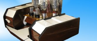
Winter is “free time” for air conditioners.
Therefore, you can do something for the soul. It’s decided - we’ll make a tube amplifier. I’ll say right away that I don’t have a lot of experience in this matter. Once upon a time, at the dawn of foggy youth, color music and several ULFs from Zuev were made, and then amateur radio was abandoned for many years. So, this is the second single-ended circuit I have made, as well as the second tube design.
↑ Amplifier circuit
There were no issues with the final cascade; the option with auto-bias was chosen. But with the driver... Respected luminaries on the Internet offer, mainly for boosting, 6S41S, or SRPP, or an interstage transformer, or a driver on tetrodes and pentodes. But I wanted, as I already said, a pure triode and not bother with another transformer. As a result of experiments with 6S45P, I settled on the following mode: power supply to the anode 250 Volts, bias voltage 3.6 volts, current about 23 milliamps. The maximum anode voltage of this lamp is 150 Volts, but the design works for more than a month from 2 to 4 hours a day without any problems.
Schematic diagram
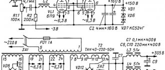
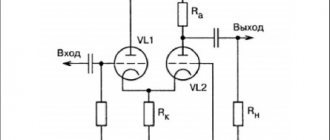
A push-pull amplifier without general feedback (its circuit is shown in Fig. 1) combines the circuit solutions we previously developed [1-3] with minor changes in relation to this option.
The power supply allows you to obtain two anode voltages from one winding of the mains transformer and, accordingly, has two smoothing filters.
Rice. 1. Schematic diagram of a 50-watt lamp UMZCH (6S41S, 6ZH9P).
A differential cascade using lamps VL1, VL2 amplifies the input signal and acts as a bass reflex. The maximum swing between their anodes is 240 V. 6Zh9P pentodes were selected taking into account the high slope of the characteristic (17.5 mA/V).
The grids of the output lamps are cross-connected to the anodes through resistors, from which a common-mode signal arrives at them, which further increases the voltage swing between the anodes of the triodes to 330 V.
The resistance of resistor R6 determines the bias voltage for the grids of output lamps - 165 V, negative polarity with respect to the cathodes of the triodes (see [3]).
Trimmer resistor R7, shunted by capacitor C2 for the passage of the alternating component of the useful signal, balances the cascade's arms with respect to direct current.
This solution made it possible to abandon the transition capacitor between the screen grids, as was done earlier in the Ekron UMZCH [2].
Thus, the total gain is quite sufficient for the specified output power (voltage up to 20.. 22 V for a load with a resistance of 8 Ohms).
With an anode current of 2 mA of each pentode of the input stage, the maximum current of each amplifier triode reaches 180 mA (corresponding to a rated power P = 50 W) and depends on the resistance of resistor R10.
So, with a resistance R10 = 10 kOhm, the quiescent current of each triode is IA0 = 70 mA, Iamax = 140 mA. If the resistance R10 = 15 kOhm, then the quiescent current IA0 = 80 mA and Iamax = 160 mA.
If the resistance R10 = 20 kOhm, then Ia0 = 90 mA, lAmax = 180 mA. In this case, the values of the supply voltage and harmonic distortion change slightly.
Button SB1 (“Control”) connects the built-in voltmeter (with zero in the middle of the scale) to the grid circuit of the output stage while adjusting the amplifier.
It can also be used to attenuate the sound level: when the contacts of the triode grid are closed, to which an anti-phase signal arrives directly from the anodes VL1, VL2, they are connected through resistor R5 and the internal resistance of the microammeter, and the gain decreases.
Resistor R11 of the power supply forms an additional bias in the cathodes of the output lamps, which can vary within -20...-40 V, depending on the input signal.
This allows you to take into account the change in drawdown of the upper (according to the circuit) power supply during operation of the amplifier and prevent overheating of powerful triodes.
The same resistor creates local feedback in the cathodes of lamps VL3, VL4 in order to improve the symmetry and linearity of the output stage.
In order to form a more even and simultaneous signal limitation (in different polarities) when maximum power is reached, resistors R3 and R8 were introduced.
They create local positive feedback in the shoulders of the output stage (without disturbing its stability), which contributes to an increase in the gain of the output stage.
From the anodes of the output lamps, the signal goes to the output transformer T1, to the secondary winding of which an speaker with a resistance of 6...12 Ohms is connected. Indicated in the diagram in Fig. 1, the voltage and current values correspond to the absence of an input signal.
↑ Details
Show/Hide text
C1 68000 μF x 6.3V C2 6.8 μF x 63V (K73-16) C3 2 μF x 315V (MBGO-2) C4 0.01 μF x 500V (K31-11) C5 6800 pF x 500V (KSO-5 ) C6 4700 μF x 100V C7 3.9 μF x 160V (K73-16) C8 6800 pF x 500V (KSO-5) L1 13 turns PEV-0.46 on a 1K (2W) resistor
R1 50K ALPS (inexpensive) R2 91K (PTMN-0.5) R3 5.6K (C5-37V-8W) R4 56 (PTMN-0.5) R5 100 (PTMN-1) R6 91 K (PTMN-0 .5) R7 91 K (PTMN-0.5) R8 790 (S5-35VR-25W)
VL1 6С45П-Э VL2 6С41С
DataSheet
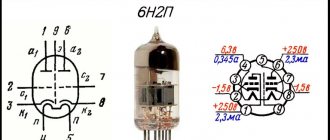
| Connection diagram for lamp electrodes 6С41С | Lamp body 6С41С |
Description
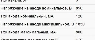
Triode for operation as a control lamp in electronic voltage stabilizers. The design is in a glass shell, baseless. Weight 100 g. Basic parameters at Un = 6.3 V, Ua = 90 V, Rk = 40 Ohm
| Parameter | Conditions | 6С41С | Unit change |
| Analogue | — | — | — |
| Filament current | — | 2.8±0.3 | A |
| Anode current | — | 240±90 | mA |
| Reverse grid current | — | ≤5 | µA |
| Leakage current between cathode and heater | — | ≤100 | µA |
| Slope characteristic | — | 19±7 | mA/V |
| Internal resistance | — | 150 | Ohm |
| Vibration noise voltage | Ra = 2 kOhm | ≤300 | mV |
| Interelectrode capacitances | entrance | 11±6 | pF |
| day off | 6±3 | ||
| checkpoint | 15±5 | ||
| between cathode and heater | ≤45 | ||
| Running time | — | ≥1250 | h |
| Criteria for evaluation | |||
| Reverse grid current | — | ≤15 | µA |
| Anode current | — | ≥150 | mA |
Operating limits
| Parameter | Conditions | 6С41С | Unit change |
| Filament voltage | — | 5.7-6.9 | IN |
| Anode voltage | — | 450 | IN |
| when the lamp is turned on | 600 | ||
| Grid voltage negative | — | 0.5-250 | IN |
| Voltage between cathode and heater | — | 300 | IN |
| Cathode current | — | 310 | mA |
| Power dissipated by the anode | — | 25 | W |
| Grid circuit resistance | — | 0.2 | MOhm* |
| Lamp bottle temperature | — | 270 | °C |
| Ambient operating temperature range | — | -60…+70 | °C |
For a description of all parameters, see the letter designations of the radio tube parameters.
*When the lamp operates as a control lamp in circuits of electronic voltage stabilizers, the resistance in the grid circuit, which is also a load in the anode circuit of the control lamp, should not exceed 1.5 MOhm.
Limit values of anode current and power dissipated by the anode during parallel operation of lamps
| N* | Resistance in the cathode circuit of each lamp, Ohm | ||||||||
| 0 | 10 | 20 | 30 | 40 | 50 | 60 | 70 | 80 | |
| Anode current of each lamp, mA | |||||||||
| 1 | 300 | 300 | 300 | 300 | 300 | 300 | 300 | 300 | 300 |
| 2 | 210 | 225 | 235 | 243 | 250 | 255 | 259 | 262 | 265 |
| 3 | 180 | 200 | 214 | 225 | 234 | 240 | 246 | 250 | 254 |
| 4 | 164 | 187 | 204 | 215 | 225 | 233 | 239 | 243 | 248 |
| 5 | 156 | 181 | 197 | 210 | 220 | 228 | 234 | 240 | 245 |
| 6 | 150 | 175 | 192 | 206 | 217 | 226 | 232 | 237 | 242 |
| 7 | 145 | 173 | 189 | 203 | 215 | 223 | 230 | 236 | 241 |
| 8 | 142 | 169 | 187 | 201 | 212 | 222 | 229 | 234 | 240 |
| 9 | 140 | 167 | 186 | 200 | 211 | 220 | 228 | 233 | 239 |
| 10 | 138 | 165 | 184 | 198 | 210 | 220 | 227 | 232 | 238 |
Continuation
| Resistance in the cathode circuit of each lamp, Ohm | |||||||||
| 0 | 10 | 20 | 30 | 40 | 50 | 60 | 70 | 80 | |
| Power dissipated by the anode of each lamp, W | |||||||||
| 1 | 25 | 25 | 25 | 25 | 25 | 25 | 25 | 25 | 25 |
| 2 | 17.5 | 18.5 | 19.5 | 20.3 | 20.8 | 21.2 | 21.6 | 21.8 | 22.1 |
| 3 | 15 | 16.7 | 17.8 | 18.7 | 19.4 | 20 | 20.5 | 20.8 | 21.2 |
| 4 | 13.7 | 15.6 | 17 | 17.9 | 18.8 | 19.4 | 19.9 | 20.3 | 20.7 |
| 5 | 13 | 15 | 16.4 | 17.4 | 18.3 | 19 | 19.6 | 20 | 20.4 |
| 6 | 12.5 | 14.6 | 16 | 17.1 | 18.1 | 18.8 | 19.3 | 19.7 | 20.2 |
| 7 | 12.1 | 14.2 | 15.8 | 16.9 | 17.9 | 18.6 | 19.2 | 19.6 | 20.1 |
| 8 | 11.8 | 14.1 | 15.6 | 16.8 | 17.7 | 18.5 | 19.1 | 19.5 | 20 |
| 9 | 11.6 | 13.9 | 15.5 | 16.6 | 17.6 | 18.4 | 19 | 19.4 | 19.9 |
| 10 | 11.5 | 13.3 | 15.3 | 16.5 | 17.5 | 18.3 | 18.9 | 19.3 | 19.8 |
If you find an error, please select a piece of text and press Ctrl+Enter.
↑ Power supply and capacitor discharge
The power supply is assembled on a TAN-123-220-50 transformer.
“Electronic chokes” are used with stabilization and delay of the anode voltage supply. The delay time is about 1 minute. Diode bridges based on ultra-fast diodes HER503. A mains choke from an old computer power supply was used as a choke. The transistors are installed on small radiators through insulating gaskets. Electrolytic capacitors are shunted with K73-17 capacitors and KSO mica capacitors. Relay P1 contains a circuit for discharging filter capacitors after turning off the power. Any relay for a voltage of 6 Volts with 2 groups of normally closed or switching contacts.
↑ Design
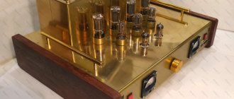
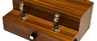
The amplifier is assembled on the basis of a housing from an old Sony VCR.
The top and bottom covers were taken from it. Inside there is a frame made of aluminum corner 15x15 mm. At the rear of this frame there is a power transformer and power supplies for the final stage and driver, as well as a capacitor discharge board after the power is turned off. This part is separated from the amplifier itself by a partition made of galvanized steel 0.7 mm thick. The rear panel, made of one-sided foil PCB, contains a power connector with a fuse, input and output jacks.
The installation of the amplifier itself was carried out in a combined way: everything that relates to the final stage is mounted in a hinged manner on the block (transition capacitors are also located there), and the driver is assembled on a single-sided printed circuit board. The lamp sockets are soldered on the conductor side.
Output transformers are mounted on the top cover. Two aluminum pans of suitable size, purchased from a hardware store and painted black, were used as casings. The front panel is made of 5 mm thick steel sheet and painted in chrome color with spray paint.
↑ Impressions
There is nothing to measure the parameters with, but I can say the following “by ear”: the amplifier turned out to be almost omnivorous, it perfectly plays any genres - Vysotsky, Aria, Space, Ello, Aguzarova.
The picture is very dynamic, the bass is deep and fast, the highs do not whistle or hurt the ears. When you listen to Vysotsky, it seems that he is here in the room. There is absolutely no background, even if you put your ear to the speaker, I didn’t even expect it.) The power is quite enough for the Magnat Monitor 2000 acoustics (with its 220 watts and a sensitivity of 93 dB) and a room of 24 sq.m. In general, I am pleased, and I bring to your discussion what happened. I beg you not to judge strictly because... In general, I am an amateur in this matter.
Audio Wikipedia
On 6С41С I did both SE and PP. Not a bad lamp, strong, durable, can easily tolerate 30 watts at the anode, voltage up to 400 volts without breakdowns (I haven’t tried it further). The sound of the stars in the sky is not enough, but if you put a euphonious driver in front of it, you will get a very good amplifier, with a power of up to 8 watts, which in some cases is more than enough.
Low-voltage modes are interesting with it: 180 V, 160 mA, -60 V on the grid, for example
Well, the 6C41C lamp is not that bad at all. For example, the single-cycle on it with drive through the interstage on 6S15P was quite good in sound. With careful fine-tuning of the sound during the six months that it stood with me. The SE 300B standing parallel to it was significantly inferior in dynamics, speed and depth. And at the end of the final development of both devices it is also clear. At a low price, 6S41S (we have 40–50 rubles) is a good option for beginners
I liked this 6S41S mode when I tortured: 200 V, 150 MA, - 68 V, under load - 2 kilos. By the way, these lamps easily tolerate 30 watts at the anode, and even more! Shalin
6С41С bulbs, just like 6С33С, are killed precisely by introducing it from the driver side into the grid currents. If the driver is dead and the Kusilenia is small, everything will stand)) but if the same 45ka with a Kus of under 100... then it can easily kill 41 or 33 light bulbs without stabilization measures taken. IMHO - we need an interstage and an ALA circuit with some adaptations for 41 (halves of 33). But if UN does not give a swing of about 70, then the scheme will not play very well. I’m currently using a 6C33C with one unconnected heater)) hypothetically it’s almost )) equivalent to a 6C41C... only the cylinder is two or three times larger. The thermal stress of the structure is much less. Outputs - just from Priboy, slightly modified for use with 6S33C single-cycle switching... Gaidar
There were 6S41S with a different type of getter, the same as the 6S19P. In a cup so small inside a Shalin balloon
TN is a hot getter, if I remember correctly, and Bokarev himself saw the same one on 6p45s
It turns out there is still a getter in 6s19p? Yes? You can’t see the plaque at all! You can see the plate, there’s some kind of crap on it
It uses a non-spray getter made of porous titanium. This getter is used quite often: in almost all metal-glass and metal-ceramic lamps
It seems that these lamps endure even more abrupt modes CALMLY. Alexey, this is not “exorbitant” for you, it’s just “exorbitant”. Now I have “exorbitant” - 36 watts of dissipation (now), today or tomorrow I’m planning a small alteration inside the amplifier, at the same time I’ll go up to 40 watts, or maybe more Two words in defense of the lamp - in terms of sound, of course, it does not compete for the palm of absolute primacy (although it sounds very good), but in terms of electrical and design parameters - just lala! When I started it for the first time, I didn’t pay attention at first, I got carried away by the sound - so, I dropped 50 watts (!) on the anode, so what? But nothing - she blushed and worked as if nothing had happened - although her bias was automatic (75 ohms at the cathode) - without any incidents. Later, I still lowered the power, sacrificed a little for the sake of completely abandoning anything in the cathode - and now it lives perfectly well with a fix at 36-37 watts at the anode, I’ll bring it to 40 and calm down, while the NETWORK WALKS AS IT WANTS. I don’t see any point in having a machine for this lamp, because... autobias is a necessary evil that should be avoided whenever possible. Vikt0r
I'm a little late, I went to Moscow yesterday. I support the opinion of the forum participants regarding the 6С41С with and without a getter. The sound is absolutely the same. I agree with Lesha Shalin that “bald” lamps are more aesthetically pleasing. By the way, since the 6G7 is now working as a driver (the current through it, you know how much it is, is minuscule), I increased the current through the 6S41S to 105 mA. It seems like the sound has become a little denser. Alexander Torres. Sanya, hello. That's what I'm talking about. Do you remember, in some thread I wrote that there are lamps that are very sensitive to changes in current, and there are lamps that do not feel it at all. I can also say about 6S41S that it reacts. I started with 90ma and eventually settled on 105ma. Excellent microdynamics, etc. Best regards, Vadim Puzanov.
I've been looking at 6s41 for a long time, but after the new year I finally assembled a SE on two 41s in parallel. Before that I listened to it on 6s19. In my opinion, 41 is much more interesting. the bass is fundamental, the highs are very clear. So far the design for me is unrivaled from what I have done. Belkovod
I generally agree about the better sound of the 6S41S over the 6S19P.
What could be better than Svetlana's 6С18С? Only 6С41С Svetlana! Shalin
Let's think for ourselves first... this is what happened to me when I tried to find a point with MINIMUM DISTORTION. RT: current 175 anode voltage 145 bias 46. with Ra = 5600 the power is slightly less than a watt but the alpha is very large. 17. It is clear that the mode is very inconvenient, but the triangles on the ACX are almost the same. Lex
I also liked almost the same one. I chose 146 V anode-cathode, quiescent current 165 mA, bias -45 V wizard
There is another option 5.7 kOhm 130 mA Evgeniy 073
I once liked this mode for 6S41S: 225 V, 120 mA, -86 V on the grid, Ra = 1.77 kOhm. I ran a lamp with such a trance throughout the entire working unit - from 150 volts anode-cathode to 330 volts.
To the ear, this mode was the most harmonious. Ri for 6С41С at the indicated point is 220 ohms. The trans had active winding resistances of 17+17 ohms. (secondaries - given of course). Shalin
I started experimenting with 41 lamps a long time ago, listened to them on breadboards, and only 3 months ago I finished working on the housing. From experience I can say that VACs do not always exactly match what is in the reference book. however, the Oren lamp sounds good at half power, and when reaching maximum it becomes a little harsh, but this is also all relative, since in my opinion, a comparison of its sound with expensive “Japanese” shows the advantage of the 41. But there is one more nuance, after As the sound warms up, it gets better even at full power. In my case, two paralleled lamps are capable of delivering 12 watts, which is always sufficient, and excellent sound at half (6 watts) also provides the required result in almost all cases. If we talk about the sound itself, then those who listened to 6s19p will find many differences in the voice of 41 and the main thing is that the dynamics and bass here 41 have practically no competitors. Belkovod
Just on topic. This Saturday in Moscow, an amplifier with 41 tubes, according to Yu. Makarov’s ideology, easily beat ONGAKU. The owner of the latter was crying. No comments. georgiy
6С41С easily tolerates 35–40 watts at the anode. In modern manufacturer datasheets, Pmax = 30 watts. Shalin
In general, lamps 6S33S, 6S41S and 6S19P are... how to say, not the best choice for a lover
of after-sounds and reverberations.
Exactly the same opinion, they are all quite “oaky” There is only one joy from them - a little Ri. Imho, shamanic dances with intensity will not help much here...
Again, imho, from this list probably the minimum oak is 1/2 6С33С, i.e. turned on at one heat. The sound is far from the same as the 6S41C, although in terms of parameters the half of the 33rd and the 41st are quite close.
Paralleled 2-3 pieces of 6S19P are also far from a gift. Besides, I really don’t like paralleling lamps - no matter how you choose them, there will still be a “Tyapnitsky choir” (to a greater or lesser extent)
6S41S definitely merged 1/2 of the 33rd, both “in terms of sound” and formally - in terms of linearity and spectrum. Maybe I have “such” 33rd and 41st, x/s... But the fact remains that half of the 33rd is better than the 41st. L0ki

