In audio frequency power amplifiers (APPAs) made according to an inverting amplifier circuit, it is often necessary to increase the input impedance to a standard value in order to turn on the level control at the input [1-3].
A regulator based on an emitter follower with a dynamic load, which has low nonlinear distortions, is proposed. The devices can be used in other UMZCHs that do not have a volume control at the input.
↑ Schematic diagram and characteristics of the buffer stage
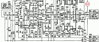
After the publication of my article Silicon vs. Germanium in amplifiers of the same retro structure and the new germanium whale at the end, I was often asked the question about connecting the volume control to the amplifier (see Fig. 1).
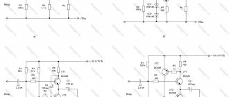
Rice. 1. Schematic diagram of a UMZCH with a retro structure on silicon transistors
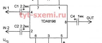
In fact, the input impedance of the amplifier turns out to be low and is determined by the resistance R1 (620 Ohms). To increase the input resistance to an acceptable value, allowing you to turn on the R0 (“Volume”) volume control at the input, I recommend using a buffer stage (emitter follower). In Fig. Figure 2 shows a schematic diagram of a stereophonic version of the buffer stage.
Fragment excluded. The full version is available to patrons and full members of the community.
To increase the load capacity, current sources VT2, R3 and VT4, R5 are introduced into the emitters of repeaters VT1, VT3, the base circuits of which transistors are powered by a common parametric voltage stabilizer HL1, R4. The currents of sources VT2, VT4 are selected equal to about 11 mA.
Characteristics:
Supply voltage: 15 V; Current consumption: 26 mA; Lower frequency level – 0.5 dB: 4 Hz; Output impedance: 3.3 ohms; Harmonic coefficient in the entire range of operating frequencies (20...20000 Hz) at Uin=1 V, Rн=620 Ohm: no more than 0.017%.
note
that the polarity of capacitor C1 in the UMZCH (Fig. 1), taking into account the connection to the buffer stage, is reversed.
It is advisable to power the buffer stage from a stabilized source, for example, from a power supply based on 7815 or LM317 microcircuits, connected according to a standard circuit.
A selection of boards for adjusting the volume when assembling your own power amplifier
When assembling a DIY audio amplifier, the question arises: how to adjust the volume? The simplest option is a dual variable resistor. But this is the 21st century. But what about without leaving the couch or using digital technologies.
Let's look at simple analog and complex digital solutions. All boards are sold on Aliexpress. There is the widest range for those interested in sound. All of the options listed are for use in DIY audio projects.
Let's list from simple to... interesting.
Variable resistor ALPS RK27
Buy here
The selection opens with the simplest and most reliable option - a variable resistor. But not entirely simple, ALPS RK27 is a proven and high-quality option for volume control.
Ratings are 10, 20, 50, 100, 250 and 500 kOhm. Shaft diameter 6 mm, length 25 mm. The spread of resistance across channels is minimal.
The mounting board is included. It is more convenient to solder wires to it and there is no risk of damaging the regulator.
Motorized volume control with input selector
Buy here
This, in fact, is also an analog volume control with a variable resistor, but the functionality is expanded.
- Remote control
- Selector for three relay inputs controlled by an encoder
- Screen
- Motorized volume
- Mute sound
The screen (1602) shows the active input and volume level.
The board is powered by 9V 1A AC voltage.
Motorized volume control with selector without screen
Buy here
Another version of the motorized regulator with remote control.
Difference from the previous one:
- Convenient remote control
- 4 signal inputs
- No screen, LED input indication
- There is an option to select the input by button or encoder
Cables between blocks included.
Typical variable resistor resistance: 50K. The device is powered by 5-12 VAC.
Relay volume control
Buy here
This is a type of discrete volume control. The precision resistors (1%) are switched by eight relays, and the variable resistor is not directly connected to the input signal.
The advantages of this solution:
- No rattle when adjusting
- Independent channels
- No channel imbalance
- Can be placed near the input connectors, and the regulator placed on the front panel
Board dimensions 86x72 mm, power supply DC 5 V.
Pre-amp board for LC75342
Buy here
An interesting option both for a preamplifier and for integration into a power amplifier. Built on the LC75342 chip from SANYO, it has a tone block.
Functional:
- Remote control
- Selector for 4 inputs on a relay
- Screen and encoder
- 80 steps volume control, 1 dB step
- Adjustment of bass (±20 dB), treble (±10 dB) and balance
- Muting the sound
- Settings memory
Power: 12 V AC.
Pre-amplifier board on PGA2311
Buy here
Speaking of volume control, we cannot ignore the PGA2311. The regulator on this board is in the title photo in the collection.
Volume adjustment from -95 dB to +10 dB in 1 dB steps. The gain is only 31 dB.
There is also a remote control, a screen and a selector for three inputs with encoder control.
The microcircuit is good and accurate. One bad thing is that there are a lot of fakes. But changing it is not a problem.
Board power: AC voltage 9-0-9 V 1 A.
Implementation of PGA2311 by SURE
Buy here
High-quality implementation of a pre-amplifier on the PGA2311 from Sure. The level is controlled by an encoder on a separate board.
Characteristics:
- Adjustment: -95.5 to 10 dB
- Step: 1.5 dB
- THD+N: 0.0006%
- S/N: 108 dB
Board power: 12 V constant voltage.
Advanced controller on MUSES72320
Buy here
The selection is completed by a sophisticated version on MUSES72320. Audiophile quality.
There are several screen options in the lot, including VFD and several power options.
Adjustable from 0 to -111.5 dB in 0.25 dB steps. Channel separation: - 120 dB.
For uncompromising DIY.
I hope the selection of boards for volume control was useful and you will choose a solution for your DIY amplifier to suit your taste and budget.
Happy shopping!
↑ Details and setting up the buffer
The emitter follower uses resistors with a power of 0.25 or 0.125 W, radial-type oxide capacitors for an operating temperature of +105ºС.
Red LED of any type with a diameter of 3 mm, for example BL-B51V1. In addition to those indicated in the diagram, KT3102 transistors with any letter indices can be supplied. Variable resistor R0 (its resistance can be from 10 to 50 kOhm) is imported, for example, ALPS RK09L 50k for Audio is good. Also look at Chinese cheap alternatives like R097-D16-6PIN, but it is difficult to be sure that they have regulation characteristic “A”.
Buffer Stage Parts List
VT1 – VT3 – Transistor BC546 – 4 pcs., HL1 – LED red d=3 mm BL-B51V1 – 1 pc., R1, R6 – Res.-0.25-68 kOhm (blue, grey, orange, gold) – 2 pcs., R2, R7–Res.-0.25-160 kOhm (brown, blue, yellow, golden) – 2 pcs., R3, R5– Res.-0.25-100 Ohm (brown, black, brown, golden) – 2 pcs., R4 – Res.-0.25-3 kOhm (orange, black, red, golden) – 1 pc., R8 – Res.-0.25-39 Ohm (orange, white, black, golden) – 1 pc., C1, C3 – Cond. 10/25V 0511 +105°C– 2 pcs., C2 – Cond. 47/16V 0511 +105°С – 1 piece, C4 – Cond. 470/25V 1016 +105°C – 1 pc., Printed circuit board 45x48 mm – 1 pc.
The placement of elements on the emitter follower printed circuit board is shown in Fig. 3.
Rice. 3. Placement of parts on the printed circuit board
DC modes are shown in the diagram shown in Fig. 2. With proper installation and serviceable parts, adjustment is usually not required. The voltages at the emitters of transistors VT1, VT3, if necessary, can be adjusted by selecting resistors R1 and R6, respectively.
Preface
The devas was made purely out of sporting interest, I just wanted to make such a craft. The device is based on an encoder and Digispark - a small Arduino-compatible board from Digistump based on the Attiny85 microcontroller. There are boards with a micro-USB connector, I used the option with a regular USB type A connector, link:
Well, the above-mentioned incremental encoder with a button, link:
Device diagram
The red and green wires are the encoder button and close when the knob is pressed. Blue, black and brown are the output of the encoder to track the rotation of the handle.
↑ Summary
Similar buffer stages can also be used with an amplifier based on germanium transistors [1, Fig.
5], as well as with the amplifier of our kit Project 008 “GeAmp1970”. Stereo (2 channels) amplifier with germanium transistors. Assembly kit. Since these amplifiers are powered from a source of negative polarity, it is advisable to install pnp transistors BC556 (KT3107) in the buffer stage, and reverse the polarity of the HL1 LED and all oxide capacitors C1 - C4. The described level controller will be appropriate with UMZCH Quad and others [3, 4].
PCB and housing
I decided to make a device in a cylindrical case with a large “twist”. From solid beech I carved a blank for the body.
I machined a handle for the encoder from aluminum of the same diameter.
Based on the dimensions of the internal diameter of a wooden blank, I drew a board in Sprint-Layout
Download link - here
I made a board using LUT
I installed the encoder and USB connector (I chose USB type B for reliability), cut off the “connector” of the Digispark board a little and soldered it to the main board. I connected Digispark to the encoder using wires.
In order to secure the board evenly in the case, I glued washers under the mounting holes on the back side.
I cut a rectangular hole in the wooden case for a USB type B connector. This turned out to be the most labor-intensive process, the case is relatively small, so I had to work as carefully as possible. After this, the wood was treated with linseed oil.
I secured the insides of the body with self-tapping screws.
The encoder “walked” a little inside the case, in order to fix it, I made such a plate from PCB
The plate is placed on the encoder axis, fixed with two nuts, its dimensions are exactly the inner diameter of the housing. Now the encoder fits like a glove
All that remains is to put on a large aluminum “twist”
Demonstration of the device operation
↑ List of sources mentioned
1. Silicon vs germanium in amplifiers of the same retro structure and a new germanium whale at the end.
2. Project 008 "GeAmp1970". Stereo (2 channels) amplifier with germanium transistors. Assembly kit. 3. Project-009 v.2 “QUAD CLONE”. Classic Hi-Fi amplifier (2 channels, without PP). Assembly kit. 4. Chinese Quad 405 beeps (excitement?) at high volume from smart and laptop. Thank you for your attention!
Happy New Year!
3Description of serial volume control signal M62429
To control the M62429 chip, a serial interface with packet data transmission is used. The length of one data packet is 11 bits. The structure of the package is shown in the figure.
Structure of the M62429 chip control package
The first bit transmits the channel number, the second - whether to use independent or simultaneous channel control, then 7 bits are reserved for the volume code, and the packet ends with two bits equal to “1”.
It is important to know the frequency and data pulse parameters. The microcircuit is controlled by a square wave (duty factor is 2), the minimum pulse duration tWHC (like tWLC) is 1.6 μs, and the period tcr is 4 μs. The remaining characteristics of the pulses are given in the technical description (datasheet), which can be downloaded from the links below.
Timing diagram of the information exchange signal with the M62429 chip