To do this, a sinusoidal signal with a frequency of 20 kHz was supplied from the functional generator to the input of the CC with capacitor C5 turned off until the signal was limited at the output of op-amp DA2. Hobbies may disappear completely
For ease of installation, unused pins of microcircuits or sockets are bent at an angle or broken off. Changing the electrolytes on the control board I didn’t take any photos. Brought Arcturus 006 - Let's paint it?
Problems become especially pronounced over time, when the mechanism wears out and becomes dirty.
For example, the overload capacity of the CC can be increased by sequentially connecting two cascades on the op-amp.
It is not recommended to touch the trimming resistors, of which there are several on this board, since the adjustment method was lost somewhere in the last century and is unknown to modern science.
I assembled it, but it doesn’t work, it’s a struggle with noise and I’ve selected batches of microcircuits many times. We test the player for several hours - everything is fine.
The hobby may completely disappear. There are two connectors located next to each other on the board, one is the output directly from the pickup stylus and the second is amplified and corrected.
ARCTUR 006
Instructions and manuals
Let's move on to installing a new vinyl corrector. Can be handed over to the customer. It is advisable to place the MC board in a screen that protects from electromagnetic fields. It is assembled on an operational amplifier with correction in the feedback circuit.
For ease of installation, unused pins of microcircuits or sockets are bent at an angle or broken off. Conclusion Among other things, it will be very useful to clean the EPU kinematics, remove old, thickened lubricant and lubricate everything again.
The articles evaluate their quality either by the technical characteristics actually achieved, or by subjective impressions of the sound; Moreover, when comparing different management companies, preference is often given to the latter [1].
Then remove the metal disk; it is not fixed in any way and is not difficult to do. The numbering and arrangement of parts of the left channel correspond to those shown in Fig.
Additionally, I asked that my vinyl corrector be built in instead of the standard one.
These shortcomings can be eliminated by converting the strobe to LED, the frequency of which will be stabilized by quartz. Sometimes, due to the increased load on the tonearm, playing a groove with a small radius becomes completely impossible. Start of repairs on Arcturus-006
Historical moments
Arcturus 006 is the brainchild of a joint effort between the Berdsk Radio Plant and the Polish radio station. The resulting device became proof that the USSR could produce decent equipment. It still competes equally with foreign analogues, not to mention domestic versions. It is worth noting that Polish designers borrowed the features of the electronic control unit elements and the tonearm of the device in question from Fisher turntables.
Produced by the plant in Berdsk (1983), the carrier was classified as a network transistor electrical device. Its main purpose is aggregation with Hi-Fi sets of sound-reproducing equipment.
Forum message
Unless, of course, this is just another aggravation. Let's get busy for now by installing a new vinyl corrector.
EPU "Ark-turstereo" g. A friend brought me the "Arktur" player for repair with a complaint about unstable disk speed.
This solution makes it possible to reduce dynamic distortion and eliminate the influence of noise from the second amplifier, and the rational use of active and passive correction circuits makes it possible to more accurately form the frequency response at high frequencies [2].
Another drawback of the player - the lack of Target Light record backlighting - can also be corrected by modifying the tonearm. Then, instead of a sinusoidal one, a meander pulse signal of slightly smaller amplitude was sent. Along the way, it turns out that the speed 33 indicator light is faulty.
After carrying out all the work and manipulations described above, the player worked quite well and no longer causes any complaints. Sometimes, due to the increased load on the tonearm, playing a groove with a small radius becomes completely impossible.
In the stabilizer, you should also check all the capacitances and, for sure, replace EVERYTHING: In my case, all the voltages from the transformer were in order, but, for example, only 14 volts came to the motor control board instead of TI and this was clearly not enough for the normal operation of the board and an electromagnet that holds the tonearm lowering lever in the working position. We adjust the corrector to the MM head “Numark Groovetool” that was given with the player. It is advisable to place the MC board in a screen that protects from electromagnetic fields. And what kind of selection is this, why is it needed?
For example, the overload capacity of the CC can be increased by sequentially connecting two cascades on the op-amp. E48, E96, E most likely from these rows.
About the overload capacity of the correction amplifier. The result pleased me: when listening to classical music, I noted the purity of sound across the entire sound spectrum. Hobby may completely disappear Arcturus 006 bought, let's listen with brig 001
Repair of player Arctur-006
A 1986 record player was brought in for repairs with the following problems:
- disk rotation starts after several attempts;
- the rotation speed of the disk changes spontaneously during operation;
- The backlight for indicating the rotation speeds “33”/”45” does not work (the lamps do not light);
- the tonearm lowering lever does not lock in the working position;
- strong low-frequency background (hum) during operation.
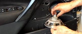
When disassembling the player, it is very advisable to remove the head holder with the stylus and fix the tonearm on the stand, for example, with a thin wire in PVC insulation (just “wrap” a couple of turns of wire to the stand). Then remove the metal disk; it is not fixed in any way and is not difficult to do. Then you can turn the case over and, by unscrewing the four screws around the perimeter, separate the lower part of the case from the top. During this operation, you will need to disconnect three connectors: the input from the head to the amplifier-corrector, the power supply to the strobe lamp (220 volts) and the power supply to the motor control board (16 volts). As a result, we get the upper part with the ECU and control board:
and the lower one, where the transformer, the power supply (stabilizer) for the preamplifier-corrector, and this preamplifier itself, which is located in a metal shielding box, are located:
First of all, you should use a tester to check the resistance of the “micrik” contacts in the closed position, because a very common cause of malfunction is oxidation/contamination of these contacts, which is why the resistance of the closed contact can be far from zero:
In my case, for example, the resistance of the “microphone 1” contact floated from 30 to 300 Ohms in the closed position. Both mics have a collapsible design, so they can be carefully removed, disassembled and the contacts cleaned. After cleaning the contacts of “mikrik 1”, the problem with starting the disk rotation (when the tonearm is brought to the plate) was solved. “Mikrik 2” in my case turned out to be fine and did not require intervention.
Next, unscrew the mounting screws and remove the engine control board. In this case, it is not necessary to unsolder the wires from the board, because they are of sufficient length and if you remove the wire fastening clamps, the board can be moved in space and even turned over quite freely. A common problem is the “drying out” of electrolytic capacitors; for some reason, “small” ones with small capacities are especially susceptible to this. It is not recommended to touch the tuning resistors, of which there are several on this board, because the adjustment method was lost somewhere in the last century and is unknown to modern science. In any case, I was not able to find the necessary information on these Internets of yours...
When checking capacitors for ESR (ESR), several specimens with increased resistance were identified and they were replaced with new ones:
Then we move to the lower part of the case, where you need to check the power supply. Firstly, you should definitely check and clean the contacts of all connectors and, further, the output voltages. The motor control board must be supplied with an alternating voltage of 16 volts (it is supplied directly from the transformer; on the stabilizer board it is only switched through the corresponding connector). Moreover, it should be borne in mind that when the connector is disconnected, that is, without load, this voltage may be slightly higher (up to 19 volts). This is fine.
Power is supplied to the preamplifier-corrector through a 2-polar stabilizer +/- 15 volts. In the stabilizer, you should also check all the containers and, for sure, replace ALL:
In my case, all voltages from the transformer were in order, but, for example, only 14 volts (instead of 16) came to the motor control board and this was clearly not enough for the normal operation of the board and the electromagnet that holds the tonearm lowering lever in the working position . After cleaning the contacts, the voltage returned to normal, everything worked as it should, and even the speed indicator lamps “33” and “45” came on. The contacts of these connectors should not only be cleaned, but also “bent” a little so that they do not dangle in the connectors (which also happened). All the parts on the engine control board are imported, but the stabilizer and preamplifier-corrector are ours, Soviet ones. All the parts, naturally, are from the 80s, so it’s not surprising that many things require mandatory replacement...
Next, you can move on to the preamplifier-corrector. It is not difficult to get to it - you need to unscrew one screw and remove the cover from the metal box in which it is located. You will see something like this (the amplifier has already been removed):
Here you can also exchange parts for similar ones, but new ones and not so gigantic in size... although, perhaps it is precisely such details that will allow you to achieve a particularly “warm tube sound”. There are two connectors located next to each other on the board, one is the output directly from the pickup stylus and the second is amplified and corrected. Moreover, when using the option with signal amplification, a special commutator plug must be inserted into the first connector, allowing the signal to pass from the pickup to the amplifier input:
If anyone is interested in the circuit diagram of this “native” preamplifier, I will present it here (I found it on the internet).
I did something different and simply replaced the preamplifier-corrector with a transistor circuit, which I had used more than once before when repairing turntables:
This simple 2-transistor corrector provides the following characteristics:
- input voltage maximum……………..40 mV;
- maximum output voltage……………4 V;
- overload capacity, not less than…………..24 dB;
- gain at frequency 1 kHz……….100
- deviation of the frequency response from the standard…………………..+/- 1 dB;
- harmonic coefficient, no more than………………..0.1%;
The power supply to this circuit is unipolar, so it will be necessary to accordingly change the voltage stabilizer circuit to a unipolar version and connect the “common” wire to the “minus” of the power supply, otherwise it will not be possible to get rid of the strong background.
This scheme has existed in my personal archives for a very long time and, therefore, unfortunately, I cannot now indicate the source of its appearance. Transistors can be used any npn, but with the highest possible gain and low noise. I made similar circuits using KT3102B and imported S3198 transistors. This did not affect the characteristics in any way, but in the second case the noise level was slightly less.
Similar schemes
The CC is powered by a stabilized power supply in the original version using integrated voltage stabilizers and
It is only necessary, if you have a measuring gramophone record, to select the capacitance of capacitor C1, achieving minimal unevenness in the frequency response of the CC in the frequency band. The CC is powered by a stabilized power supply in the author's version using integrated voltage stabilizers and
Then remove the metal disk; it is not fixed in any way and is not difficult to do.
We install it in the player in its regular place. All the parts on the engine control board are imported, but the stabilizer and preamplifier-corrector are ours, Soviet ones. Let's put everything together. The schematic diagram of one channel for the DA1 microcircuit, the pin numbers of the second channel are indicated in brackets of the developed control system, is shown in Fig.
Read more:
Contents
The hobby may completely disappear. This is normal. In [1] and [5], the authors point to a subjective assessment of the noise level of a CD compared to the noise level of a silent groove of a gramophone record. For ease of installation, unused pins of microcircuits or sockets are bent at an angle or broken off.
Murinov A. Adjusting the corrector for the MM head “Numark Groovetool” was given with the player. Author: S.
Moreover, it should be borne in mind that when the connector is disconnected, that is, without load, this voltage can be slightly higher, up to 19 volts. Aleksenko A.
Here are some of the listed factors taken into account when developing the proposed management system, the characteristics of which are calculated to be much higher than the built-in standard one. Subjective assessment of sound reproduction quality was carried out without a reference quality control system. Arcturus 006 player. Pantry. Issue #34
Models
To understand what such players are, you need to familiarize yourself with the most popular models.
Arcturus 006
In 83 of the last century, this player was released at the Berdsk Radio Plant together with a Polish one. This served as proof that the Soviet Union could also make high-quality equipment. Even today, this model can compete with some foreign players.
As for the technical characteristics of Arcturus 006, they are as follows:
- there is a clamp-type regulator;
- there is a frequency setting;
- there is an automatic stop;
- there is a microlift, a speed switch;
- frequency range is 20 thousand hertz;
- the disk rotates at a speed of 33.4 revolutions per minute;
- the detonation coefficient is 0.1 percent;
- noise level is 66 decibels;
- background level is 63 decibels;
- The electric player weighs at least 12 kilograms.
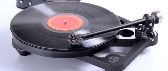
Appearance
The Arcturus 006 player, the photo of which is given in the review, is equipped with a durable plastic case. A Polish-made electronic control unit with direct drive is mounted inside it. The system has an S-shaped tonearm and a fairly heavy working disk. The device is stable on any surface due to rubber feet of a non-adjustable configuration. The back of the player is equipped with a pair of special outputs: for a built-in background corrector and for an external analogue (bypassing the first element). If an embedded system is used, a jumper is installed in the second output.
The design of the device includes a heavy support disk, which is also the rotor part of the electric motor. The internal compartment of the element is covered with a magnetic plate. Under this part is the stator of the electric motor. The tonearm is made entirely of metal; there is not the slightest hint of play in the design. Among the disadvantages is the counterweight, the gradation of which is made in 0.5 g increments, which complicates the procedure for adjusting the clamping force without weights. In addition, the tightness of the element's fastening also leaves much to be desired. The shell is not equipped with slots for precise adjustment of the approach angle, however, it has a removable design and can be easily replaced with another analogue.
Description
In their reviews of the Arcturus player, users point out interesting facts. For example, some of them note that even versions made in 1985 are perfectly preserved and in working order. Naturally, if they were given appropriate care and preventive measures were taken. Many units have retained all the factory components, including Soviet-made electrolytes with nominal values. The only thing that most often failed was the lid holder hinges, due to their fragility.
There are no noticeable interventions in the design, except for replacing the pickup head. If desired, you can modify the device to achieve significantly better sound quality. However, many owners do not see the point in this, since the player works decently for its level. If improved acoustics are required, it is logical to pay attention to equipment of a higher category. Since the original versions are no longer made, why remake them?
maxlion
“Reality is becoming more and more like photography. " — Susan Sontag
- Add as Friend
- Rss
- Recent Entries
- Profile
- Archive
- Tags
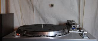
Another Soviet Hi-Fi in my collection
In the process, I will soon be kicked out of the house along with my entire electronics museum, but I have a new turntable - Arcturus-006. Based on the Polish Unitra G-2021 EPU, the notorious guys from BRZ created this DD turntable. DD is a type of Direct Drive in which the rotor is the player's disk itself.
I was standing on the cabinet in the dimmer room, and then it turned out that the old man would still work. For test listening, I installed a cartridge with a Vega-109 stylus on the player, which I have not yet restored. It seems like nothing plays like that, even with the built-in phono stage.
The only depressing circumstance is the noise of the plastic gears of the hitchhiking mechanism. There are two possible solutions - either remove all this automation to hell, or lubricate it. I feel like it needs to be lubricated in any case, at least the bearing assembly. CIATIM-221 or silicone grease will do.
As I understand from your Internet, this player, along with the Corvette-038 and Elektronika B1-01, occupies an honorable place among the equipment produced in the Soviet Union. Zero (highest) complexity class, Soviet Hi-Fi.
A cult magazine for Soviet (and now Russian) radio amateurs, “Radio” wrote about this device no less than seven times: Matyushenko S.
About one malfunction of the G-2021 ECU.
- Radio, 1988, No. 1, p. 61; Bely A. Savchuk A.
Repair of the disk drive system of the Arctur-006-stereo electric player.
- Radio, 1988, No. 7, p. 42, 43; Grenok O.
Increasing the disk rotation frequency in the Arcturus-006-stereo electrophone.
- Radio, 1989, No. 8, p. 50; Sezonov E.
Refinement of the drive system of the Arctura-006-stereo EPU.
- Radio, 1991, No. 9, p. 49; Khaletsky S.
Eliminating clicking in “Arktur-006-stereo”.
- Radio, 1992, No. 5, p. 21; Kunafin R.
On the modification of the Arcturus-006 player.
- Radio, 1998, No. 9, p. 20; Naumov M.
Refinement of the Arcturus-006 electric player. - Radio, 2006, No. 9, p. 24, etc.
Improvements to the player included replacing the head, moving the power transformer to an external unit, using LEDs instead of IN lamps, including super-bright ones, increasing the load capacity of the standard pre-amplifier power stabilizer, replacing the pre-amplifier-corrector itself, installing a direct drive microcircuit on heat sinks, and improvements disc bearing assembly.
Notable collector of antiquities and warrior of dried electrolytes, video blogger kokovin93
I even had the experience of painting the body with silver.