for each lane.
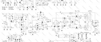
↑ Tube equalizer circuit
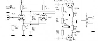
Below is a diagram of the device.
Fragment excluded. The full version is available to patrons and full members of the community.
The input switch allows you to mix signals from three sources. Each input has a smooth signal level control. Using three-position toggle switches, it is possible to turn off each channel, either turn it on completely, or with an attenuation of -6 dB.
Trimmer resistor R6 allows you to adjust the gain of the device within certain limits (to obtain identical channel gain).
The depth of maximum rise and attenuation is set by selecting resistors Ro1, Ro2. In my case, the Ro1 value ranged from 300 Ohm to 2 kOhm. And for Ro2 - from zero to 300 Ohms. Potentiometer data:
volume controls - 470 kOhm, maybe less, 100 kOhm, 220 kOhm. Rt tone controls - from 10 kOhm to 47 kOhm. You may have to pick up Ro1, Ro2. I have 33 kOhm ones, which I found.
Using resistances Rq, the quality factor of each circuit is selected. The values of these resistances range from 0 to 1 kOhm. The filter chokes are wound on rings measuring 16×10*5 mm made of ferrite grade 2000NM.
The table shows the values of capacitors and inductances of bandpass filters.
The frequency response was adjusted using the AudioTester program. The level of noise and background, with the middle positions of the tone controls, is less than -60 dB.
Soldering - All about electronics
You can also experiment with the 6 kHz - 10 kHz bell equalizer. The timbre is controlled by variable resistors 1R2—5R2. A parametric equalizer contains filters whose resonant frequency and quality factor can be adjusted independently of each other. Boosting in the lower mids will likely make the sound harsh, so it's always best to use a high rise/fall filter if you want to add extra punch to your guitar sound.
The frequency signal processing channel, forming a parallel feedback circuit, consists of an inverter on DA2, notch filters Z1-ZN and passive adders on resistors 1R1-NR2.
Use the top fade-in filter to brighten your voice if needed; bell equalizer is unlikely to be applicable here.
Assembling a 10-band equalizer on TL On one of the Czech sites, the language of the article was determined by GOOGLE translator, a project for a 10-band equalizer implemented on quad TL operational amplifiers was found. Thanks to this, the frequency response at the edges of the filter passband is leveled and the required range of gain adjustment in each band is obtained.
Op-amp DA1 contains input and output buffer amplifiers. Don't forget to calculate the resistor that will be in series with the LED.
The equalizer is adjusted in the following sequence.
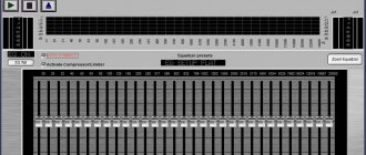
Graphic equalizer. Variable resistors Rp1 - RpN, with the help of which the correction depth is adjusted, are connected between the inverting inputs of the op-amp, thereby eliminating mutual influence between adjustments in different frequency channels. Equalizer LA3607 measurements and tests
↑ Design and details
The design of the device is similar to that of the previously described tube amplifier and has the following overall dimensions: 365 mm * 260 mm * 60 mm.
The body is made of sheet iron with a thickness of 0.7 - 1.2 mm. Front and rear panels made of sheet aluminum 0.8-1.0 mm thick, drawings below. The equalizer is assembled on 3 printed circuit boards: tone block board, power board, amplifier board. For board drawings, see the attached archive.
The power transformer is made on a ring core. The mains winding is left factory - at 220 V, there are two secondary windings: anode at 120-130 Volts, which is used to obtain voltages of +150 V and -150 V, and filament at 6.3 Volts.
To reduce the background glow, the lamps are powered by constant voltage. In the filament rectifier, a dual diode from a computer power supply is used as diode D3 to obtain a minimum voltage drop across it.
EQUALIZER SCHEMATIC DIAGRAMSCHEMES OVERVIEW
START
The next tone control already has six control bands, and a separate operational amplifier is used for each band. The original version of this equalizer was five-band, but by expanding the number of bands and using quad operational amplifiers, you can get by with just 4 DIP14 housings for the stereo version, instead of 16 DIP8, which would be required when using single op-amps. The schematic diagram of this equalizer is shown in Figure 22. This option can already be safely called a graphic equalizer, since when using slider variable resistors installed in one line, the overall frequency response of the equalizer will be visually visible, i.e. graphic display of the adjustments made.
Figure 22 Schematic diagram of a six-band graphic equalizer.
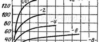
Figures 23-28 show curves showing the change in frequency response depending on the change in the resistance of the control resistors.
Figure 23 20 Hz adjustment.
Figure 24 100 Hz adjustment.
Figure 25 500 Hz adjustment.
Figure 26 2000 Hz adjustment.
Figure 27 1000 Hz adjustment.
Figure 28 20000 Hz adjustment.
As can be seen from the figures, the curves of changes in the frequency response have a fairly symmetrical shape both in the frequency range and in the limits of increasing and decreasing a particular band, which allows the use of this equalizer in medium and high-class equipment.
The use of bandpass filters can be organized not only as in the previous version, but also somewhat differently. An example is the equalizer shown in Figure 29. Each bandpass filter is essentially an electronic analogue of a capacitor and inductor connected in series.
Figure 29 Schematic diagram of a six-band graphic equalizer.
Figures 30-35 show the frequency response at the extreme positions of the variable resistors. By the way, the range of adjustments can be slightly expanded by adjusting the resistor values at the “edges” of the variables, but not less than 1.5 kOhm. The quality factor of the filters certainly leaves much to be desired, however, the circuitry of this equalizer is quite popular.
Figure 30 30 Hz adjustment
Figure 31 90 Hz adjustment
Figure 32 200 Hz adjustment
Figure 33 700 Hz adjustment
Figure 34 2000 Hz adjustment
Figure 35 HF Adjustment
The frequency range is slightly shifted to the low-frequency side, so it is better to recalculate if you plan to use this design not in domestic conditions.
Another version of an eight-band equalizer is shown in Figure 36. In terms of circuitry, this tone control consists of six band-pass filters, the signals after which are simply summed and amplified by a buffer amplifier. This option has its own gain factor that is quite large, so the input amplifier X1 serves as a divider of the input signal, i.e. initially weakens it.
Figure 36. Schematic diagram of a graphic equalizer on an op-amp
When constructing the frequency response of the equalizer, a rather interesting thing became clear - this regulator only enhances the selected band, and the attenuation is so small that it can be neglected (Figure 37).
Figure 37 Change in frequency response depending on the position of the variable resistor X2 motor.
Of course, this behavior raised suspicions about the correctness of transferring the circuit diagram to the simulator. A thorough check did not reveal any errors, so it was decided to check what actually happens in the filters themselves depending on the change in the positions of the variable resistors. To begin with, ALL variable resistor sliders were moved to a position that increases the rise of each band and the frequency response was measured at the outputs of the op amp X10-X17. What happened was pleasing to the eye - the change in shape is quite symmetrical and the quality factor is not bad (Figure 38).
Figure 38 Frequency response of each filter with increasing filter gain
Next, the variable resistor sliders were moved to decrease each filter and the frequency response at the output of each filter was again taken. The picture also turned out to be quite beautiful - neither the frequency nor the quality factor have changed (Figure 39).
Figure 39 Frequency response of each filter with decreasing filter gain
What happens in this case if both the range of filter adjustments and the quality factor are good, but in the end the rise is only 9 dB, and the rolloff is less? The answer to this question is quite simple. The equalizer circuitry is to blame for everything, namely the summation of signals after bandpass filters. The fact is that when the amplitude of one section of the frequency range increases, the signal passing through the adder is greatly attenuated and, as a result, the amplitude increases not by the expected 20 dB, but by only 9 dB. When the amplitude of one section of the frequency range is weakened, the attenuation itself occurs, but only in the filter, and at the output of the adder, this attenuation is compensated by even frequency responses in the attenuated section by other filters. Thus, the more bands there are in the equalizer using this circuit design, the smaller the adjustment range will be. Based on all of the above, we can conclude that the author of this publication is ALL
I did the calculations by assembling only one or two filters, and all calculations and measurements were carried out not in a full-fledged device, but only using its fragments, since in a finished device it is not possible to obtain a five-band equalizer with an adjustment range of ±12 dB, especially -12 dB.
However, absolutely speaking FUUUU!!!
There is no need to rely on this circuitry, since on its basis you can build a pretty good LF-HF tone control, and the rise and fall will occur exactly where the nonlinearity of the frequency response of the acoustic system is maximum and where most often it is necessary to slightly raise the amplitude. To do this, it is necessary to leave only the upper and lower bandpass filters, and reduce the values of resistors R37, R44 and R46 to 10 kOhm. The result is quite decent adjustment of the frequency response at the edges of the audio range (Figure 40).
Figure 40 The shape of the change in frequency response at the extreme positions of the variable resistor sliders of the “shortened” equalizer.
The same filters can be used in devices that only require an increase in the frequency response at a certain frequency or the isolation of a certain frequency, for example, a spectrum analyzer or a dynamic light installation (color music).
As the next device for adjusting the frequency response, let's consider a schematic diagram of an equalizer with adjustable bandpass filters and not quite conventional circuitry. The schematic diagram of this device is shown in Figure 41.
Figure 41 Schematic diagram of a professional five-band equalizer.
This equalizer differs from previous versions primarily in the use of two operational amplifiers for one bandpass filter. This increase in detail is primarily paid off by obtaining additional capabilities, namely the ability to adjust the pseudo-resonance frequency of the filter and adjust the quality factor. This, in turn, completely eliminates the selection of frequency-setting elements (in the equalizer it is recommended to use parts with a spread of no more than 1%, otherwise selection is necessary to obtain the required frequencies and similar adjustments in stereo versions). In addition, if the 22 kOhm trimming resistors in bandpass filters are replaced with 10 kOhm ones and connected in series with 22 kOhm variables, you can get a parametric equalizer that has much greater capabilities compared to graphic equalizers. The main advantage of parametric equalizers is the ability to adjust not only the level of a particular frequency, but also select the frequency itself, as well as change the slope of the rollovers or rises of the variable frequency. Therefore, a three-band parametric equalizer is preferable to a five-band graphic one, but there is nothing to say about a five-band parametric equalizer - this is a device for recording studios and requires a trained operator. But let’s return to the diagram and for now consider the operation of one bandpass filter. Figure 42 shows the change in the frequency response of the entire device at the maximum and minimum quality factor of the mid-frequency bandpass filter (the quality factor changes in the other filters in the same way).
Figure 42 Change in quality factor, regulated by resistors X14-X18.
Figure 43 Frequency change, regulated by resistors X8-X12.
Figure 43 shows the changes in frequency of the bandpass filter. The figures show quite clearly the undulation of the frequency characteristics at the edges of the adjustable frequency. The appearance of this effect is associated with an unreasonable increase in the adjustment range - up to a level of ±16 dB, which in itself is already too large a range. By reducing the adjustment range (increasing the value of resistors R1-R5), you can achieve a fairly significant reduction in this waveform, and with an adjustment range of ±12 dB, the maximum peaks of the “waves” will be at the level of 1-1.5 dB, which is already quite difficult to distinguish by ear. Figure 44 shows a schematic diagram of a ten-band graphic equalizer using the same circuitry. In fact, this scheme differs from the previous one only in the increased number of stripes, everything else is completely the same.
Figure 44 Schematic diagram of a ten-band graphic equalizer.
The approximate chat band in this embodiment is adjusted by appropriate resistors and has the form shown in Figure 45, although it can be changed depending on the needs of a particular sound engineer.
Figure 45 Approximate frequency grid of a ten-band equalizer.
In addition to building equalizers, bandpass filters can be used one at a time to correct a specific frequency or range. For example, if you use only the lowest-pass bandpass filter, you can get a rather interesting filter for a subwoofer. Well, here are actually all the main options for tone controls with all the pros and cons.
Frequencies that are useful to remember
The network (power) is noisy at 50 Hz (and multiplying). To eliminate this, you need to remove the frequencies of 50 and 100 Hz using a parametric equalizer, the bandwidth of which is quite narrow. This will then not noticeably affect the overall sound, but will eliminate network noise. A graphic equalizer (one-third of an octave) is also applicable in this situation, but it is better not to use other types of equalizers for this, since they have too wide (zone of influence) and the adjustment can seriously change the sound of a 6ac guitar.
The lower frequencies of the bass guitar and bass drum lie in the region of 40 Hz or less. To give these sounds power (attack), adjust the frequency to 80 Hz. Many modern microphones designed for the bao drum have a slight peak at this frequency, which allows for a nice, thick sound.
The lower frequency of an electric guitar is 80 Hz. To eliminate barreliness, you need to cut out the frequency of 200 Hz; To eliminate the unpleasant harsh overtone, weaken it around 1 kHz. In any case, the sweep equalizer must be adjusted by ear. To achieve a high-pitched sound, use a hi shelving control filter. You can also experiment with bell equalizer (6 kHz - 10 kHz). To add some venom, to make a rock guitar sound sting, scan the region from 1.5 kHz to 4 kHz, find the frequency you want and turn it down until the attack is where you want it to be.
The main problem with acoustic guitars is usually that they sound barrely (due to improper microphones, microphone position, room acoustics - or simply because the instrument is bad). To correct this shortcoming, you can use a sweeper equaliser: the region of the “harmful” frequency is usually between 200 Hz and 500 Hz; it needs to be cut out. Boosting in the lower mids will likely make the sound harsh, so it's always best to use a high rise/fall filter if you want to add extra punch to your guitar sound.
Vocals also occupy a large portion of the frequency range, with the 2-4 kHz region being adjusted to improve articulation. Try to avoid high gain whenever possible, as the natural sound of the voice may be lost. Use the top fade-in filter to brighten your voice if needed; bell equalizer is unlikely to be applicable here.
ARCHIVE WITH MODELS FOR MICROCAP
Description of the methodology for constructing equalizer models in the MICROCAP simulator:
Site administration address
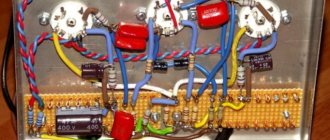
↑ Photos
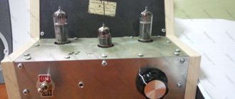
Below are photos of the structure. The inscriptions on the front and back panels are made using LUT and covered with acrylic varnish from a spray can.
View from above
Front view
Back view