High-quality transistor audio amplifiers require a powerful bipolar power supply of 35-45 volts, which is not always available to radio amateurs. A simple 12-volt audio amplifier is easy to make with your own hands. Many devices are made using transistors or integrated circuits. The advantage of such designs is that they can be used in a car and connected to a battery. The devices consume little current, and the limited power output allows for the use of small heat sinks and thin wires.
How to make a 12 volt sound amplifier
The simplest designs with low-voltage power supply are assembled on special integrated circuits. The number of discrete elements is minimal; they do not require setup or adjustment and, if installed correctly, begin to work immediately. But many people prefer to use transistor units, which are easy to assemble from old radio components. It is easy to assemble a 12 V sound amplifier with your own hands using a complementary pair of transistors of different conductivities.
This design can be connected to any power source with a voltage from 9 to 15 volts. The device uses the following domestically produced semiconductor devices:
- BC560C – KT3107I
- BC337 – KT503
- TIP32A – KT8177A
- TIP31A – KT8176A
- 1N4148 – KD522B
The adjustment comes down to setting a voltage value equal to half the supply voltage at the emitters of the output transistors. Transistors of the final stage are installed on small heat sinks. The device produces about 2 watts. The simple circuit allows you to experiment with other, more powerful transistors to increase the output parameters.
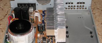
You can assemble a powerful 12-volt audio amplifier with your own hands according to the following scheme.
To reduce the level of intrinsic noise, the KT315 transistors need to be replaced with low-noise KT3102. The complementary pair KT818-KT819 is used as output stage transistors. The disadvantage of the circuit is that it is powered from a bipolar source, but in this case the output easily produces up to 25 watts of power. The output characteristics of all audio designs are limited by the supply voltage, so high-power final stages will require the use of voltage converters.
Circuits and instructions for making an amplifier at home
Each circuit is unique and depends on the sound source (old or modern digital technology), power supply, and expected final dimensions. It is assembled on a printed circuit board, which will make the device compact and more convenient. During the assembly process, you cannot do without a soldering iron or soldering station.
The British John Linsley-Hood circuit is based on four transistors without microcircuits. It allows you to similarly repeat the shape of the input signal, resulting in only pure gain and a sine wave at the output.
The simplest and most common option for manufacturing a single-channel amplifier is to use a microcircuit based on it, supplemented with resistors and capacitors.
It is recommended for a novice master to use ready-made files in the Sprint Layout computer program to create and view circuit diagrams. Creating your own can only be done by experienced specialists.
How to make a 12 volt audio amplifier
Transistor units assembled on a modern element base have proven themselves to be reliable devices that provide good quality sound. But despite the simplicity of the circuit solutions, they require adjustment and configuration. In this case, structures assembled using integral components are much more convenient for beginners. The circuit of a simple 12-volt audio amplifier is assembled in just half an hour and, in the absence of installation errors, immediately begins to work.
The module on one chip has the following advantages:
- No external elements
- Does not require adjustment
- Operation stability
- Low power consumption
- No heatsink required
- Has short circuit protection
When working with integrated elements, the question often arises of how to make an audio amplifier with 12 volts of power, but with more power. To do this, you can use more expensive microcircuits or use cheap elements, but use a bridge circuit.
Two common TDA2003 microcircuits connected in a bridge circuit provide the following characteristics at a 4 Ohm load:
- Output power – up to 12 W
- Maximum current consumption – 3.5 A
- Quiescent current less than 50 mA
This device can be used in a car, since the amplifier produces 12 watts of power with a power supply of 14.2 volts, which corresponds to the voltage in the on-board network. To organize a stereophonic path, two such channels will be required. You can assemble a 12-volt sound amplifier with your own hands using a different scheme.
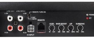
It uses a two-channel LA4708 microcircuit and a five-volt voltage regulator on KREN5A. Capacitors C1, C2, C5 and C6 in the output circuits must be film. All presented circuits are final stages. These devices can be used with radios, tuners, players or household computers. The signal level from the output is sufficient to drive the output stages and obtain the required power. In other cases, the use of an additional cascade will be required. This design can include a multi-band equalizer, which will greatly improve the parameters.
Let's finalize the scheme
The diagram presented in the document is somewhat incomplete. For normal operation, the circuit should be supplemented with input circuits.
Operational amplifiers are equally good at amplifying both AC and DC voltages. Therefore, despite all sorts of audiophile troubles, it is considered good form to add a capacitor to the input.
Of course, modern sources do not provide a constant voltage to the output, but I don’t know where you will connect the amplifier... and I’m not eager to be responsible for your burned-out headphones
In addition to the capacitor that cuts off the DC voltage, you should add a resistor going to ground. Such a resistor will ensure that the non-inverting input of the op-amp is tied to ground. On the other side. together with the capacitor it forms an RC differentiating circuit.
The resulting RC circuit ( R5 , C1 ) will cut off both DC voltage and infra-low frequencies. They do not carry useful information, but they significantly load the amplifier with current. At the ratings indicated in the diagram, the cutoff frequency is 16 Hz. When using a 220nF capacitor, the cutoff frequency will drop to approximately 7Hz. Further increase in capacity does not make much sense.
To exclude possible self-excitation of the op-amp, it would not be amiss to limit the upper range. To do this, install a small capacitor R2
Circuit R2 C2 will act as a low pass filter. With the specified part ratings, the cutoff frequency will be about 100 kHz.
Component quality
Component quality
Capacitor C1 must be non-polar. Better polypropylene or film. It is better to use ceramic capacitor C2. The accuracy of capacitors is not so important, but it is better to use an accuracy of at least 5%. Resistors should preferably have an accuracy of no worse than 1%
Good microcircuits are not cheap. For example, for two original OPA2604 , which were offered in the original scheme, you will have to pay about $23.
But it is not at all necessary to immediately purchase the most expensive. To begin with, you can supply something from the assortment of the nearest radio parts store, and gradually replace them with higher quality components. The board will work on any parts.
Prices for operational amplifiers vary widely and more expensive does not always mean better sound. To begin with, you can install something inexpensive and accessible, for example, the beloved NE5532 ($0.3). It is highly desirable that it be made by Phillips.
Subsequently, you can play with replacing the op-amp as much as you want. If we consider op-amps of a higher class, then OPA2134, OPA2132, OPA2406, AD8066, AD823, AD8397… have proven themselves well for sound.
Do not order the cheapest microcircuits from AliExpress and other Chinese stores. There are a lot of fake chips out there. They will work as expected, but it may not be the OPA2134 you ordered, but a rather cheap TL061 labeled OPA2134...
But I managed to find a store that sells truly original microcircuits. And in general it has very high quality audio components. Including the top ones. I highly recommend this store.
Additional Tips
Experienced radio amateurs can achieve even cleaner sound from the amplifier if they create the circuit themselves. It is quite difficult to do this without auxiliary tools.
To avoid confusion, it is recommended to use the Sprint Layout program. It has the following functions:
- designing circuits of low and medium complexity;
- wiring design;
- viewing models in three dimensions;
- ability to create a parts library.
You can download and install a Russified program with additional functionality for free. To do this, you should look for version 6 of the software (not the official one, but the translated one). It is compatible with all English versions up to the fifth.
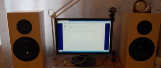
The program will help you create visual plans that are much more useful in practice than photos of homemade sound amplifiers and their circuits.
On a laptop
In order to amplify the sound signal, you must purchase the following components:
- Capacitor n/a 0.1 uF 2 pcs
- Capacitor n 100.220, 470 uF 1 pc.
- Fixed resistor 10, 4.7 Ohm, 1 pc.
- Switch.
- Speaker connector.
There are many assembly schemes that are essentially no different. They can be downloaded from the Internet. After everything is connected, it is necessary to make a reliable case in which there will be holes for cooling the radiator.
Device base
Beginner radio amateurs first of all ask themselves: what can they use to assemble a simple sound amplifier at home? The operation of the device is based on transistors or microcircuits, or a rare option is possible - on lamps. Let's take a closer look at each of them.