It would seem that what could be simpler, connect the amplifier to the power supply , and you can enjoy your favorite music?
However, if we remember that the amplifier essentially modulates the voltage of the power source according to the law of the input signal, it becomes clear that the design and installation of the power supply should be approached very responsibly.
Otherwise, mistakes and miscalculations made in this case can ruin (in terms of sound) any, even the highest quality and most expensive amplifier.
Stabilizer or filter?
Surprisingly, most often simple circuits with a transformer, rectifier and smoothing capacitor are used to power power amplifiers. Although most electronic devices today use stabilized power supplies. The reason for this is that it is cheaper and easier to design an amplifier that has a high power supply ripple suppression coefficient than to make a relatively powerful stabilizer. Today, the ripple suppression level of a typical amplifier is about 60 dB for a frequency of 100Hz, which practically corresponds to the parameters of a voltage stabilizer. The use of direct current sources, differential stages, separate filters in the power supply circuits of the stages and other circuit techniques in amplifier stages makes it possible to achieve even greater values.
The power supply to the output stages is most often made unstabilized. Due to the presence of 100% negative feedback, unity gain, and the presence of OOOS, the penetration of background and supply voltage ripples into the output is prevented.
The amplifier's output stage is essentially a voltage (supply) regulator until it enters clipping (limiting) mode. Then the supply voltage ripple (100 Hz) modulates the output signal, which sounds simply terrible:
If for amplifiers with unipolar power supply only the upper half-wave of the signal is modulated, then for amplifiers with bipolar power supply both half-waves of the signal are modulated. Most amplifiers are characterized by this effect at high signals (powers), but it is not reflected in any way in the technical characteristics. In a well designed amplifier, clipping should not occur.
To test your amplifier (more precisely, the power supply of your amplifier), you can conduct an experiment. Apply a signal to the amplifier input with a frequency slightly higher than you can hear. In my case, 15 kHz is enough :(. Increase the amplitude of the input signal until the amplifier goes into clipping. In this case, you will hear a hum (100 Hz) in the speakers. By its level you can evaluate the quality of the amplifier's power supply.
Warning! Be sure to turn off the tweeter of your speaker system before this experiment, otherwise it may fail.
A stabilized power supply avoids this effect and leads to reduced distortion during prolonged overloads. However, taking into account the instability of the network voltage, the power loss on the stabilizer itself is approximately 20%.
Another way to reduce the clipping effect is to feed the stages through separate RC filters, which also reduces the power somewhat.
This is rarely used in serial technology, since in addition to reducing power, the cost of the product also increases. In addition, the use of a stabilizer in class AB amplifiers can lead to excitation of the amplifier due to the resonance of the feedback loops of the amplifier and stabilizer.
Power losses can be significantly reduced if you use modern switching power supplies. However, other problems arise here: low reliability (the number of elements in such a power supply is significantly larger), high cost (for single and small-scale production), high level of RF interference.
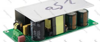
A typical power supply circuit for an amplifier with an output power of 50W is shown in the figure:
The output voltage due to smoothing capacitors is approximately 1.4 times greater than the output voltage of the transformer.
Calculation of the number of turns and winding
To power the remaining electronic units of the amplifier, it was decided to wind several separate secondary windings. A wooden shuttle was made to wind the coils with enameled copper wire. It can also be made from fiberglass or plastic.
Rice. 2. Shuttle for winding a toroidal transformer.
Winding was done with enameled copper wire, which was available:
- for 4 power windings UMZCH - wire with a diameter of 1.5 mm;
- for other windings - 0.6 mm.
I selected the number of turns for the secondary windings experimentally, since I did not know the exact number of turns of the primary winding. The essence of the method:
- We wind 20 turns of any wire;
- We connect the primary winding of the transformer to the ~220V network and measure the voltage on the wound 20 turns;
- We divide the required voltage by that obtained from 20 turns - we find out how many times 20 turns are needed for winding.
For example: we need 25V, and from 20 turns we get 5V, 25V/5V=5 - we need to wind 20 turns 5 times, that is, 100 turns.
The calculation of the length of the required wire was done as follows: I wound 20 turns of wire, made a mark on it with a marker, reeled it off and measured its length. I divided the required number of turns by 20, multiplied the resulting value by the length of 20 turns of wire - I got approximately the required length of wire for winding. By adding 1-2 meters of reserve to the total length, you can wind the wire onto the shuttle and safely cut it off.
For example: you need 100 turns of wire, the length of 20 wound turns is 1.3 meters, we find out how many times 1.3 meters each need to be wound to get 100 turns - 100/20 = 5, we find out the total length of the wire (5 pieces of 1, 3m) - 1.3*5=6.5m. We add 1.5 m for reserve and get a length of 8 m.
For each subsequent winding, the measurement should be repeated, since with each new winding the wire length required by one turn will increase.
To wind each pair of 25 Volt windings, two wires were laid in parallel on the shuttle (for 2 windings). After winding, the end of the first winding is connected to the beginning of the second - we get two secondary windings for a bipolar rectifier with a connection in the middle.
After winding each pair of secondary windings to power the UMZCH circuits, they were insulated with thin fluoroplastic tape.
In this way, 6 secondary windings were wound: four for powering the UMZCH and two more for power supplies for the rest of the electronics.
Peak power
Despite these disadvantages, when powering the amplifier from an unstabilized source, you can get some bonus - short-term (peak) power is higher than the power of the power supply due to the large capacity of the filter capacitors. Experience shows that a minimum of 2000uF is required for every 10W of output power. Due to this effect, you can save on the power transformer - you can use a less powerful and, accordingly, cheaper transformer. Keep in mind that measurements on a stationary signal will not reveal this effect; it appears only during short-term peaks, that is, when listening to music.
A stabilized power supply does not have this effect.
↑ Crimp lugs and terminal blocks in UMZCH
In professional and amateur equipment, crimp lugs and terminal blocks have recently been often used (Fig. 8). What are they good for? Nothing! (Joke!). But seriously, crimp lugs and terminal blocks simplify the installation of functional units of equipment and improve its maintainability.
Rice. 8. The power supply of a high-quality UMZCH is connected using crimp terminals (100W RMS/Channel Stereo Amplifier, //www.siliconchip.com.au/)
I was skeptical about these connectors for a long time until I did my research. It turned out that the contact resistance is less than 0.01 Ohm, it is stable over time (time period of one year). In addition, chemical preparations are currently being produced that make it possible to effectively monitor the condition of connector contacts.
Parallel or series stabilizer?
There is an opinion that parallel stabilizers are better in audio devices, since the current circuit is closed in a local load-stabilizer loop (the power supply is excluded), as shown in the figure:
Installing a decoupling capacitor at the output has the same effect. But in this case, the lower frequency of the amplified signal limits it.
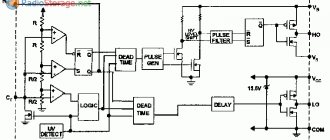
The author uses zener diodes to power operational amplifiers. In this case, it is possible to organize an indication of the supply voltage with virtually no additional costs (LEDs do not need quenching resistors):
The main thing is the voltage drop
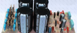
When designing printed circuit boards for power supplies and more, we must not forget that copper is not a superconductor. This is especially important for “ground” (common) conductors. If they are thin and form closed loops or long circuits, then due to the current flowing through them, a voltage drop results and the potential at different points turns out to be different.
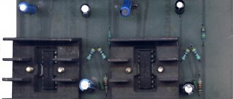
To minimize the potential difference, it is customary to route the common wire (ground) in the form of a star - when each consumer has its own conductor. The term “star” should not be taken literally. The photo shows an example of such a correct common wire layout:
In tube amplifiers, the anode load resistance of the cascades is quite high, about 4 kOhm and higher, and the currents are not very high, so the resistance of the conductors does not play a significant role. In transistor amplifiers, the resistance of the stages is significantly lower (the load generally has a resistance of 4 Ohms), and the currents are much higher than in tube amplifiers. Therefore, the influence of conductors here can be very significant.
The resistance of a trace on a printed circuit board is six times higher than the resistance of a piece of copper wire of the same length. The diameter is taken 0.71mm, this is a typical wire that is used when installing tube amplifiers.
0.036 Ohm as opposed to 0.0064 Ohm! Considering that the currents in the output stages of transistor amplifiers can be a thousand times higher than the current in a tube amplifier, we find that the voltage drop across the conductors can be 6000! times more. This may be one of the reasons why transistor amplifiers sound worse than tube amplifiers. This also explains why PCB-assembled tube amplifiers often sound worse than a surface-mounted prototype.
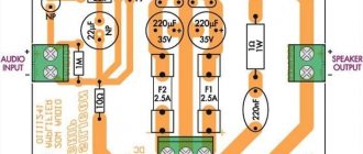
Don't forget Ohm's law! To reduce the resistance of printed conductors, you can use various techniques. For example, cover the track with a thick layer of tin or solder tinned thick wire along the track. Options are shown in the photo:
Toroidal transformer
Toroidal transformers, in comparison with transformers with armored cores made of W-shaped plates, have several advantages:
- less volume and weight;
- higher efficiency;
- better cooling for windings.
All I had to do was calculate the voltage and number of turns for the secondary windings and then wind them.
The primary winding already contained approximately 800 turns of 0.8 mm PELSHO wire; it was filled with paraffin and insulated with a layer of thin fluoroplastic tape.
By measuring the approximate dimensions of the transformer iron, you can calculate its overall power, so you can estimate whether the core is suitable for obtaining the required power or not.
Rice. 1. Dimensions of the iron core for the toroidal transformer.
- Overall power (W) = Window area (cm2) * Sectional area (cm2)
- Window area = 3.14 * (d/2)2
- Sectional area = h * ((Dd)/2)
For example, let's calculate a transformer with iron dimensions: D=14cm, d=5cm, h=5cm.
- Window area = 3.14 * (5cm/2) * (5cm/2) = 19.625 cm2
- Cross-sectional area = 5cm * ((14cm-5cm)/2) = 22.5 cm2
- Overall power = 19.625 * 22.5 = 441 W.
If you need to calculate a toroidal transformer, then here is a small selection of articles: (1Mb).
The overall power of the transformer I used turned out to be clearly less than I expected - about 250 watts.
Charge pulses
To prevent the penetration of the network background into the amplifier, it is necessary to take measures to prevent the penetration of charge pulses of the filter capacitors into the amplifier. To do this, the tracks from the rectifier must go directly to the filter capacitors. Powerful pulses of charging current circulate through them, so nothing else can be connected to them. The amplifier's power supply circuits must be connected to the terminals of the filter capacitors.
The correct connection (installation) of the power supply for an amplifier with single-supply power is shown in the figure:
Click to enlarge
The figure shows a version of the printed circuit board:
Click to enlarge
The author still comes across amplifiers in which a high background level is caused by incorrect ground wiring and connecting tracks from different “consumers” to the rectifier outputs.
↑ Ultrasound sound quality depending on its cost
Let's consider the dependence of some property of an object (in our case, the fidelity of sound reproduction) on costs (cost), Fig. 7. Such a dependence is typical for most complex systems (and ultrasonic transducer is undoubtedly a complex system); this is a law of nature.
Rice. 7. Dependence of reproduction fidelity on the cost of ultrasound; Z2>>Z1, reads “much more”
On the graph there is a section AB of linear growth, increasing BC and saturation CD. With relatively little effort (money costs), 75–85% of the object’s properties (reproduction fidelity) are achieved, and then a significant increase in the cost of ultrasonic frequency leads to only a slight increase in sound quality. Obviously, it doesn’t make sense to choose a CD plot (it’s only possible if the chickens don’t peck for money, that is, there are a lot of them).
Section AB on the graph shown in Fig. 5, is characterized by the fact that every hundred rubles spent on the acquisition (construction) of an ultrasonic frequency unit results in a noticeable increase in sound quality. From all points of view, the most optimal is the BC section corresponding to the transition from the linear increase section to the saturation section. Here, point B is the lower price level for the cost of the ultrasonic device, and point C is the upper one. Currently, the approximate price of an ultrasonic unit on an aircraft section ranges from 20 thousand rubles (entry-level ultrasonic unit) to 50 thousand rubles (mid-level ultrasonic unit). The average cost of an ultrasonic unit in the CD section is 150 thousand rubles and can reach up to 1 million rubles at point D.
Here we will not discuss the real price of the ultrasonic amplifier; it should be understood that in reality it may be dominated by components of demand, brand, marketing, etc., which are not related to the sound quality of the ultrasonic amplifier. When choosing the optimal configuration of a sound-reproducing complex, you should always remember that it must be balanced.
Ripple
Most unstabilized power supplies have only one smoothing capacitor (or several connected in parallel) after the rectifier. To improve the power quality, you can use a simple trick: divide one container into two, and connect a small resistor of 0.2-1 Ohm between them. Moreover, even two containers of a smaller nominal value may turn out to be cheaper than one large one.
This gives smoother output voltage ripple with lower harmonic levels:
At high currents, the voltage drop across the resistor can become significant. To limit it to 0.7V, you can connect a powerful diode in parallel with the resistor. In this case, however, at signal peaks, when the diode opens, the output voltage ripples will again become “hard”.
To be continued…
The article was prepared based on materials from the magazine “Practical Electronics Every Day”
Author: Jack Roseman
Free translation: Editor-in-Chief of RadioGazeta
↑ Sources mentioned
1. Titze U., Schenk K. Semiconductor circuitry: A reference guide. – M.: Mir 2. Galperin M.V. Practical circuit design in industrial automation. – M.: Energoatomizdat 3. Mosyagin V.V. Secrets of amateur radio skills. – M.: SOLON – Press 4. Rogov I.E. Design of power supplies for audio amplifiers. – M.: Infra - Engineering 5. electroclub.info: “Calculation of the UMZCH power supply” 6. Datagor article “Make your own rectifier and filter unit for UMZCH”