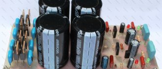
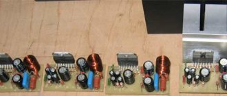
Printed circuit board for amplifier assembly
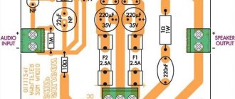
The printed circuit board here is reduced in size and double-sided. To reduce space, the resistors are 0.125 W, but you can use 0.25 W. R10 and R12 are SMD 0805 type.
In the circuit, R10 / C14 and R12 / C5 form a low-pass filter to eliminate possible penetration of high-frequency signals into the audio path. IC1 NE5532 is a pre-amplifier, using a non-inverter configuration we get a gain of about 4 times, that is, for an input of 50 mV, there will be about 200 mV at the output, which is enough to increase the signal from Bluetooth modules and the like. Of course you can change the ratio between R2/R4 and R3/R8 by changing the gain depending on the application. For example, changing resistors from 15 kOhm to 47 kOhm, we get a gain of 11 times, for 10 kOhm the gain is 3 times, and so on.
IC3 7812 is a 12 V voltage regulator that stabilizes the power supply of the NE5532 chip.
The signal goes to the TDA7379 through C1 and C6 and since the input impedance of this m/s is 10 to 15 kohms in bridged mode, the high pass filter will cut from 10 Hz using a 1uF capacitor, if anything you can change it by installing a capacitor to a higher value and lowering the cutoff frequency. Here, instead of electrolytic capacitors, it is better to use polyester ones. Polyester capacitors are more expensive at higher capacitance values.
Elements R1, R11, C4 are responsible for the standby mode and allow you to avoid the speaker clicking when the amplifier is activated; the charging time with a 47 uF capacitor is enough to avoid overloading the speakers.
For decoupling and filtering there are C5 at 1500 µF and C9 at 100 nF, for powering the operational amplifier C7 at 1000 µF and C8 at 10 nF. Since we plan to use a simple source to power the NE5532 or equivalent, we will need a "virtual ground" equal to VCC/2. To do this we use a voltage divider with two equal value resistors R5/R6 and a filter capacitor C12.
TDA7294 chip and its features
TDA7294 is the brainchild of SGS-THOMSON Microelectronics, this chip is an AB class low-frequency amplifier, and is built on field-effect transistors.
The advantages of the TDA7294 include the following:
- output power, with distortion 0.3–0.8%: 70 W for a load with a resistance of 4 Ohms, conventional circuit;
- 120 W for 8 ohm load, bridge circuit;
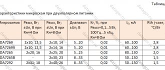
Specifications
| Technical characteristics of the TDA7294 chip | |||||
| Parameter | Conditions | Minimum | Typical | Maximum | Units |
| Supply voltage | ±10 | ±40 | IN | ||
| Frequency range | Signal 3 db Output power 1 W | 20-20000 | Hz | ||
| Long-term output power (RMS) | harmonic coefficient 0.5%: Up = ±35 V, Rn = 8 Ohm Up = ±31 V, Rn = 6 Ohm Up = ±27 V, Rn = 4 Ohm | 60 60 60 | 70 70 70 | W | |
| Peak music output power (RMS), duration 1 sec. | harmonic coefficient 10%: Up = ±38 V, Rn = 8 Ohm Up = ±33 V, Rn = 6 Ohm Up = ±29 V, Rn = 4 Ohm | 100 100 100 | W | ||
| Total harmonic distortion | Po = 5W; 1kHz Po = 0.1–50W; 20–20000Hz | 0,005 | 0,1 | % | |
| Up = ±27 V, Rn = 4 Ohm: Po = 5W; 1kHz Po = 0.1–50W; 20–20000Hz | 0,01 | 0,1 | % | ||
| Protection response temperature | 145 | °C | |||
| Quiescent current | 20 | 30 | 60 | mA | |
| Input impedance | 100 | kOhm | |||
| Voltage Gain | 24 | 30 | 40 | dB | |
| Peak output current | 10 | A | |||
| Operating temperature range | 0 | 70 | °C | ||
| Case thermal resistance | 1,5 | °C/W | |||
Pin assignment
| Pin assignment of the TDA7294 chip | |||
| IC output | Designation | Purpose | Connection |
| 1 | Stby-GND | "Signal Ground" | "General" |
| 2 | In- | Inverting input | Feedback |
| 3 | In+ | Non-inverting input | Audio input via coupling capacitor |
| 4 | In+Mute | "Signal Ground" | "General" |
| 5 | NC | Not used | – |
| 6 | Bootstrap | "Voltage boost" | Capacitor |
| 7 | +Vs | Input stage power supply (+) | Positive terminal (+) of the power supply |
| 8 | -Vs | Input stage power supply (-) | Negative terminal (-) of the power supply |
| 9 | Stby | Standby mode | Control block |
| 10 | Mute | Mute mode | |
| 11 | NC | Not used | – |
| 12 | NC | Not used | – |
| 13 | +PwVs | Output stage power supply (+) | Positive terminal (+) of the power supply |
| 14 | Out | Exit | Audio output |
| 15 | -PwVs | Output stage power supply (-) | Negative terminal (-) of the power supply |
Note. The microcircuit body is connected to the power supply negative (pins 8 and 15). Do not forget about insulating the radiator from the amplifier body or insulating the microcircuit from the radiator by installing it through a thermal pad.
I would also like to note that in my circuit (as well as in the datasheet) there is no separation of input and output lands. Therefore, in the description and in the diagram, the definitions of “general”, “ground”, “housing”, GND should be perceived as concepts of the same sense.
The difference is in the cases
The TDA7294 chip is available in two types - V (vertical) and HS (horizontal). The TDA7294V, having a classic vertical body design, was the first to roll off the production line and is still the most common and affordable.
Complex of protections
The TDA7294 chip has a number of protections:
- protection against power surges;
- protection of the output stage from short circuit or overload;
- thermal protection. When the microcircuit heats up to 145 °C, the mute mode is activated, and at 150 °C the standby mode is activated;
- protection of microcircuit pins from electrostatic discharges.
Related materials
Pre-amplifier based on TDA7318 (TDA7313) audio processor and Arduino. Part 2... Completed project. Assembly will take you approximately 15 minutes. In the first part of the article we detail...
Using MK ATMega163, ATMega163L, ATMega16 in Arduino IDE... The popular development environment Arduino IDE attracts with a large number of ready-made libraries and...
The second life of the Philips 592LN tube radio (Holland, 1947). Part 5... In this part of the article we will talk about: - the pre-amplifier and its power supply, - the power supply of the FM module...
Amateur Radio High-End. 40 best designs of lamp UMZCH for 40 years.... Amateur Radio High-End. 40 best designs of lamp UMZCH for 40 years. Small encyclopedia…
Subwoofer channel processing unit: adder, subsonic, frequency and phase regulator... Photo of my unit, the unit is made according to the second version of the board. The device is designed to form...
The second life of the Philips 592LN tube radio (Holland, 1947). Part 4. BlueTooth OVC3860 module... Hello, Datagorians! In this part of my story we will talk about the BlueTooth OVC3860 module (more...
Pinwheel "Estonia 010". New control system based on Arduino UNO... Hello, dear Datagorians! I share with you my own experience in mastering the Arduino UNO board and...
Arduino shield: accelerometer on LIS302DL... I recently assembled an arduino on atmega8, blinked the diode, I wanted more. I started studying various...
Allegro is a headphone amplifier based on LT1259... I wanted to do it quickly, but as efficiently as possible. After a short search, from…
TDA8920… The TDA8920 is a high quality Class D power amplifier with very low dissipation….
The second life of the Philips 592LN tube radio (Holland, 1947). Part 2... Today I want to share with you, dear Datagorians, how in my Philips 592LN radio I...
DIY tube Hi-Fi amplifier. Toropkin M. V…. Toropkin M.V. Do-it-yourself tube Hi-Fi amplifier. - St. Petersburg: Science and Technology, 2005. - 240 p.: ill....
↑ Analysis of datasheets and real measurements of TDA7379
TDA7379Ali
Dependence of TDA7379 output power on power supply into a 4 Ohm load
The power of the TDA7297 is in parentheses for comparison. It can be seen that with a load of 8 ohms the difference is minimal, and with a load of 4 ohms it is significant.
TDA7379
The declared 2×38W/4Ω @18V, 1KHz are possible if the power supply is stabilized. In addition, the power is specified at 10% distortion, which is unbearable distortion when limited significantly. In reality, at the threshold of the limitation, the undistorted power will be 20...30% lower, this is 25...30 W per channel, very good for such a chip. By the way, the limitation occurs very softly, according to the oscilloscope it is much better than in class D.
Comrade, consider the datagor recommendations
Attention! 800 rubles for beginners on Aliexpress Register using our link. If you are new to Aliexpress, get 800.00₽ coupons for your first order.. Digital oscilloscope DSO138
Kit for assembly
Digital oscilloscope DSO138. Kit for assembly
Function generator. Kit for assembly
Adjustable holder for easy PCB soldering
Vladimir (vladimirm2) Haifa List of all articles
Profile: vladimirm2
I live in Israel, originally from Odessa, a former military psychologist, today an engineer of network computer technologies or simply a system administrator. About ten years ago I became interested in tube sound, and at that time I built my first amplifier. I listened and adjusted for six months, I’m happy. Since then, various devices have been built, some of them thanks to the materials and help of the people of this portal. I found a lot of useful information on your resource. With respect to everyone! )
Related materials
3500 low-frequency power amplifier microcircuits and their analogues. E. F. Turuta... 3500 low-frequency power amplifier microcircuits and their analogues. E. F. Turuta Publisher: DMK...
Object "Pipe". A mystery!... Whoever guesses what this space thing is, nothing will happen to him. Write your guesses to...
5000 modern ULF microcircuits and their analogues. E.F. Turuta... 5000 modern ULF microcircuits and their analogues. E.F. Turuta Publisher: Science and Technology Year of publication:…
TDA7265… 25+25 Watt stereo amplifier with Mutam and Standby. Can be turned on in a bridge. Protection against short circuit and overheating….
Modern amplifiers on microcircuits. Bashirov S.R…. Modern amplifiers on microcircuits. Bashirov S.R. This publication discusses the design of units...
Microcircuits for switching power supplies and their application... I would like to bring to your attention the reference book “Microcircuits for switching power supplies and their...
Audio amplifier TDA7265 2x25W. The “Pipe” object is the answer... There was a bit of a false start with the riddle: I sent Igor a photo with the question “is it worth writing about this...
TDA1514A: 50-watt amplifier in 15 minutes... One of the developments - the TDA1514A chip - can help create a Hi-Fi amplifier...
Protecting USB devices from static. Chips TPD2E001, USB6B1, STF202-22T1G... Probably each of us has ever experienced a discharge of static electricity, and many...
Popular articles Children's ottoman
Amplifier on a chip TA8205, TA8210, TA8215, TA8221... A very short practical article with photos, inspired by the project of our Bulgarian friend in...
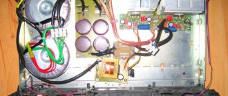
Stereo amplifier design and details
Most of the parts of the power supply are installed on a circuit board measuring 95x80 mm, Fig.Z. All components of the power supply are installed in the housing of one of the speakers with dimensions of 180x128x140 mm. The design can use fixed resistors of types S1-4, S1-14, MLT, RPM, S2-23, S2-33.
It is advisable to use a wirewound resistor R2 with a power of 2...5 W and a resistance of 10...33 Ohms. Variable resistor R10 type SPZ-Z0a or similar with a linear characteristic of the dependence of resistance on the angle of rotation of the moving contact. Instead of the MYG20-431 varistor, FNR-20K431, FNR-20K471, LF14K471, LF20K471, GNR20D431 K, TVR14-471 are suitable.
Non-polar capacitors C1 – C4, C15, C16 ceramic K10-17, K10-50 or imported. The remaining non-polar capacitors are small-sized film capacitors. Electrolytic capacitors are aluminum or tantalum oxide types K50-35, K50-68, K50-29, K53-19 or analogues.
Diodes FR155 can be replaced by any of 1 N5391 – 1 N5399, FR151 -FR157, FR201 – FR207, KD258, KD411. Schottky diodes 1N5822 can be replaced by SR360, SR306. Instead of the D815A zener diode, 1N5338 is suitable. Zener diodes BZV55C-5V6 can be replaced with 1N4734A, KS156G. LEDs can be any continuous glow with increased light output without built-in resistors, for example, the KIPD40, KIPD66 series.
The germanium pnp transistor MP26A can be replaced by MP26AB, MP25B, MP40A, MP21A, B. Instead of the AN7805 chip, KIA7805, MS7805, TL780-05C, KA7805, L7805CV are suitable. Domestic microcircuits such as KR142EN5A and KR142EN5V are not suitable for working in this design. The voltage stabilizer chip is installed on a ribbed duralumin heat sink with a cooling surface area of 70 cm2 (one side).
The UMZCH type TDA7496SA microcircuit in this design can be replaced with the TDA7496. The TDA7496S chip is not suitable for working in this design. The TDA7496SA chip is the most advanced in terms of built-in additional functions, but in the design described, only electronic volume control is used. This microcircuit is installed on a ribbed duralumin heat sink with a cooling surface area of 160 cm². Most of the UMZCH parts are installed on a circuit board measuring 95x80 mm, Fig. 4.
You can make a step-down transformer yourself. A W-shaped magnetic core with a central core area of 8.2...9 cm2 is suitable. The primary winding contains 1410 turns of winding wire (PEL or PEV type) with a diameter of 0.23...0.27 mm. Winding II contains 70 turns of winding wire with a diameter of 0.68 mm. Winding III - 120 turns of winding wire with a diameter of 0.68 mm. Several insulating layers of varnished fabric are laid between the windings. The no-load current of such a transformer will be only about 10 mA.
Instead of a homemade transformer, you can use a unified TTP-40. The IRS-101-3C switch can be replaced by the IRS-201-ВС, IRS-101-1АЗ, IRS101-12C. Switch SA2 type P2K with four groups of contacts connected in pairs in parallel can replace SDDF-3, KDC-A04, PKN-41-1-2. Chokes L1, L2 are wire jumpers with ferrite tubes 10...20 mm long placed on them. Fuse holder for 230V circuit type DP1-CM.
When assembling the elements of the UMZCH, you should carefully consider the layout of the signal and power circuits of the common wire. In the circuit diagram (Fig. 2), the power circuits of the UMZCH are shown with thick lines. Pins 11, 15, 8 DA1 and the corresponding pins BA1, BA2 must be connected to the common connection point of the negatives of capacitors C23, C24 using individual conductors or separate tracks.
Popular articles DIY flower pot decor
The signal common wire originates from pin 8 of DA2. The speaker with the UMZCH module is connected to the speaker with the power module using a four-core cable 2...4 meters long, the copper cross-section of each core is 0.75...1.0 mm2. The appearance of the assembled structure is shown in the photo at the beginning of the article. The device, manufactured flawlessly from serviceable parts, starts working immediately and does not require adjustment.
Functionality check
Sometimes the question arises - how to check the serviceability of the tda7377, especially before soldering? Unfortunately, there is no simple way to check. But usually, to diagnose the performance of the microcircuit, it is enough to check the supply pins (8,3 and 13) for short circuits. This can be done with a regular multimeter. If there is no short circuit, apply power to them. In this case, a voltage of half the supply voltage should appear at the output of the amplifier. Such a device can be considered serviceable and can be used in your circuits.
Examples of using
Using the TDA7377 chip, it is quite easy to assemble an amplifier with your own hands, with a minimum set of external components. Currently, in radio stores you can purchase radio kits for creating amplifier boards based on it with all the necessary elements for assembly. Or ready-made modules, with the necessary electronic wiring, a cooling radiator and installed volume and tone controls.
An example of such an assembly on the TDA7377 and an amplifier circuit for a subwoofer are presented in the video.