Good afternoon everyone, in this review I will tell you how you can relatively inexpensively add an audio digital signal processor (DSP) board based on the ADAU1701 chip to the ULF, using the example of your DIY amplifier / multimedia center (from my previous review), I will show how it can be controlled in on-line mode, and add what you always want, but are afraid to admit to a wide circle of connoisseurs of a short audio path - EQUALIZER, to adjust the frequency response of speaker systems and the room. The review presents the purchased boards, connection diagrams, results of use and problems encountered during implementation, which readers may help me solve.
How do you equalize the sound?
EQ Method 2
Leveling to make an instrument or mix larger and larger than life.
- Set the Boost/Cut knob to a medium BOOST level (8 or 10 dB should work).
- Scroll through the frequencies in the bass band until you find a frequency where the sound has the desired fullness.
- Adjust the amount of Boost to taste.
Interesting materials:
What is the 1 N ratio? What is a many-to-many relationship in a database? What is the ratio of zero to one? What is signal to noise ratio in audio? What is relative frequency and how to calculate? What is relative frequency in a histogram? What is relative and absolute path? What is a relative path in a URL? What is an email display name? What is thumbnail display?
CHAPTER 1. DSP components:
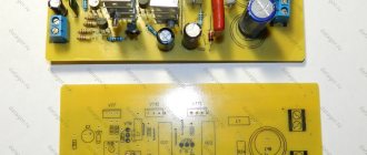
I spent a long time studying the issue of budget implementations of digital signal processors for audio (hereinafter referred to as “DSP”), everything of course came down to MiniDSP 2x4, but taking into account their delivery it somehow became completely non-budgetary. On the other hand, there were various projects on chips from Analog Devices using their SigmaStudio software, and in the end I came across a DSP board based on ADAU1701 from CHIPDIP: RDC2-0027v2, SigmaDSP ADAU1701. Digital audio processing module. V2 They have two versions of this board - RDC2-0027v1 and RDC2-0027v2. The RDC2-0027v1 is distinguished by its size, wider supply voltage ranges (5V - 36V), but the absence of EEPROM on the board, but only memory slots in DIP or SOIC packages, which must be purchased separately (which is not a problem). For the current project, I chose the RDC2-0027v2 version, which is powered by +5V and already has an EEPROM on board. The board itself looks like this:
Board diagram and connector assignments:
For my needs, this board turned out to be easy for me, two channels for the input (ADC) and four for the output (DAC), two for the speakers of the left and right channels, and one channel for the subwoofer. The performance of this DSP is also more than enough for me, since complex signal processing circuits and algorithms are not planned.
The preparation of a signal processing project for this DSP is carried out in the excellent SigmaStudio program, which they really tried to do for people, so that even I, as a humanities student, without programming experience, was able to figure it out and perform the necessary manipulations. Of course, this is not the same ease of use of MiniDSP plugins, but everything can be solved and is not at all intimidating, especially when you want to figure it out. The product page also shows connection diagrams for programmers (which are also sold by the store) for flashing EEPROM with a ready-made project from the SigmaStudio program. But I didn’t really like this option, since I need the ability to see, or rather hear, the results of processing in real time, and not have to constantly update the EEPROM and listen to the results.
Therefore, it was decided to use a solution based on the CY7C68013A chip from Cypress Semiconductor. Which can “pretend” to be a standard USBi interface from AD for connecting to a DSP via USB, with the ability to make changes online and write a project to EEPROM for subsequent loading when the DSP starts.
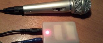
On the Youtube channel CHIPDIP there is a video on how to use this chip in operation (link to video), but the board that you can buy from them costs about 1000 rubles, and it connects somehow strangely. In the vastness of Aliexpress, I found this board on the CY7C68013A chip (EZ-USB FX2LP CY7C68013A USB logic analyzer core board+Source Code):
The reviews contain information on successful connection to the ADAU1701, so I decided to take it. This is what the board looks like in real life:
Connecting to a PC via a MiniUSB cable, when connected the red LED lights up:
The board has several operating modes, which can be changed by removing the jumpers installed on the pins, and I thought that I would have to look for the necessary combination to select the desired mode, but everything worked, as they say, “out of the box.” Without removing any jumpers, everything was determined as it should be the first time.
What is a preamplifier?
The preamplifier takes a small, high-impedance signal and converts it into a low-impedance, noise-resistant signal that is sufficient for further processing. The preamplifier provides some voltage gain, making it resistant to interference.
Preamplifiers generate electrical audio signals so that they can be further processed and amplified by a power amplifier, which adds current gain, allowing it to drive loudspeakers.
Most audio devices have preamplifiers, from AV receivers to guitar amps to televisions. If you were to connect an external preamp directly to either of these, you'd likely have to turn down the volume on the device to compensate, and you might end up with some audio distortion due to the extra gain.
For this reason, if you want to connect an external preamp to one of these devices, you will need to find a way to bypass the internal preamp. In fact, preamps are designed to work in conjunction with power amplifiers, not other audio devices.
However, in some rare cases, an external preamp may not be the best option, but the only option.
CHAPTER 3: Implementation of a DSP board in ULF, startup and problems:
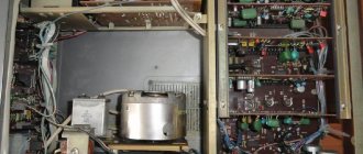
If you read my previous review, then I have a multi-level layout of components in the amplifier case, and accordingly, the new DSP board had to be placed in a new level. For the board, I prepared a new platform made of thin plexiglass and placed the board on it:
A new platform of the third level was placed already on the existing platform of the second level of the Android TVBox board:
At the first level, below them, there is the main board for preliminary volume control and input selector on the PGA2311, from which I took the +5V power supply for the DSP board and found the pins to the PGA2311 power point.
I installed everything on the platforms, the signal to the DSP input comes from the volume control board and the PGA2311 input selector, from the DSP output the signal goes directly to the ULF of the left and right channels and the ULF of the subwoofer.
From the original circuit of my amplifier, I removed the Chinese low-pass filter board of the subwoofer, and I lost that weak 50/100 Hz background, which bothered me a little, and which we discussed in the comments. An earthen loop formed through it. Most likely, I really needed to decouple the power supply resistors of the LC and PC amplifiers and the low-power stabilized bipolar ±12 V power supply from which the subwoofer's high-pass filter was powered.
To connect the CY7C68013A board to the DSP, it was necessary to make a switchable solution so that I could take the CY7C68013A board at any time, connect to the amplifier, make the necessary changes, load it into EEPROM and disconnect. Of course, you can place the CY7C68013A board itself in the case, and only output a USB connector for connecting to a laptop, but I wanted to make a separate mobile module, which I can also connect in the same way to the DSP that I am going to install in the car. To connect you need three contacts, I thought for a long time what to order so that there would be both a plug and a socket, and a small one, since the back panel of my amplifier was already clogged, until I saw a 3.5 mm stereo jack in my supplies.
Center contact - GND Left channel - SDA, Right channel - SCL
I placed the socket on the rear panel, and ran the wires from the socket directly to the board connectors:
First launch and problems:
The first launch greeted me with an eerie background.
This is no longer that small background, this is a serious background! Everything was great on the table, but there were problems again in the case. I was distracted by other things, going through possible reasons in my head, what I added, which led to the earthen loop. In the end, I came up with an idea - I came, checked, and made sure. In the 3.5 mm socket to connect the CY7C68013A board, I used the center pin for GND. The central contact of the socket is connected to the metal inlet hole, which also serves for fastening through a round nut along the thread of the socket to the panel, to the metal rear panel... I removed the GND from the board - the background disappeared, and disappeared altogether, and you cannot understand whether the amplifier is working or not. Later I found the same socket, only with a completely plastic body, and placed it in the same place, but carefully with hot glue. Loop problem solved. But I’m still fighting a fierce battle with the second problem, and I’d be glad for advice. After turning on the amplifier and supplying power to the DSP, I did not get any sound, I checked the power on the DSP board, there is +3.3 V after the converter on the board, but the ADAU1701 did not start. I pulled the power connector on the board and the DSP started up successfully. I turn off the amplifier, turn it on again - the ADAU1701 sleeps again, remove and put back the power chip on the board - it starts, remove and put it back 10 times, it starts in 10 cases out of 10. Turning off the power to the amplifier and immediately turning it on - the ADAU1701 starts up. I turned off the power from the DSP board, cut off the old USB cable, connected +5V and GND to the board, inserted the USB plug into all sources, laptop, 5V power supply for Raspberry Pi, various 5V chargers, ADAU1701 starts from all sources without problems, though with Small power supplies and USB ports of TvBox come with such terrible interference and pulsation, when connected to the USB port of a laptop everything is fine. I used a multimeter to connect the power from the volume control board and the PGA2311 input selector, when the amplifier is turned on, the voltage on the board appears with an increase, I think while the capacitors after the rectifier are charging. Perhaps when a low voltage is first applied, the ADAU1701 goes into some kind of special mode and waits, but I don’t know what. I also saw reports of this behavior on the forum on the Analog Devices website.
I have identified two solutions for myself: - supplying power to the ADAU1701 with a delay when the power is stabilized; — supply a separate low-noise switching power supply with galvanic isolation for separate power supply of ADAU1701;
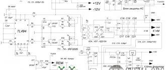
For the first option, I decided to try the following: I have speaker protection boards installed after the ULF. On the subwoofer protection board I have a FINDER 40.52S relay installed, which has two groups of contacts, but I only use one group for output to the subwoofer. Turning on the AC occurs with a delay through this relay, so I decided to use a free group of contacts to supply voltage through it to the ADAU1701. It almost worked, but the delay is not always enough to turn on the ADAU1701 without problems, I tried to increase it by increasing the capacitance of C2 according to the circuit, but for some reason the changes in the delay time are insignificant.
I would have continued along the path of looking for ways to increase the turn-on delay, if not for another problem. When turning the ADAU1701 on and off, it produces very unpleasant sounds and pops, which are not very useful for both the speakers and ears. Therefore, I am considering the second option - a low-noise switching power supply with galvanic isolation. The new power supply can generally be turned on on a permanent basis, as now, both Raspberry Pi and TVBox work for me, the consumption there is negligible. I ordered several types of small UPSs, let's see what happens with them, I hope not to hear something terrible on the air, as was the case with various USB charges. I will be glad if experienced comrades in the comments advise me on alternative solutions, perhaps simpler and more obvious ones, which I have not yet thought of.