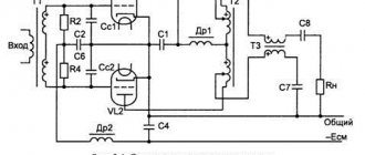
↑ Scheme of a tube amplifier by S. Sergeev
High power and the presence of suitable tubes in the driver stage persuaded me to build my first push-pull.
The amplifier sounds very good and has the following parameters: Supply voltage 360 Volts Power consumption from the network 170 W Sensitivity 0.7 Volt Output power 40 W
Armed with a list of parts, I went to the market. Unfortunately, this is the only place where you can buy radio parts in my city.
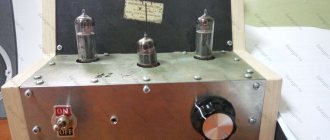
Single-ended amplifier on 6P36S
When creating this amplifier, I primarily pursued the goal of maximizing the full musicality of the 6P36S tube.
This light bulb itself is endowed with good power potential, very good sound quality, and most importantly, the 6P36S is flexible in linearity mode settings, incl. has great possibilities for adjusting the anode-grid characteristics.
But there are also vagaries that are expressed in very high demands on the preliminary stage lamp.
Historical information about the 6P36S lamp:
In September 1961, Telefunken began production of a new lamp, the EL500, designed to operate in horizontal scanning output stages with horizontal beam deflection. The EL500 is installed on a 9-pin Magnoval socket, the lamp anode is located at the top. The lamp has the following some characteristics: - heater voltage 6.3 V; — heater current 1.38 A; — anode voltage 75 V; — grid voltage 200 V; — grid voltage No. 1 -10 V; — anode current 440 mA; — grid current No. 2 30 mA. One of the first TV models to use the EL500 radio tube is the “Hansamatic Gold”, produced in Austria since 1961. By 1965, the EL500 had become widespread in European countries, and France and Finland had been producing TV models using this lamp since 1963. Some manufacturers have started producing specialized equipment using the EL500. For example, in 1965 in Belgium the company MBLE (Manufacture Belge de Lampes et de Matériel Electronique) began production of a specialized laboratory power supply “Power supply BED-002”. An interesting fact is that the EL500 radio tube is also used in the output stages of low-frequency power amplifiers. Moreover, for the first time such an implementation was carried out at the very beginning of its release, in 1961 in the Echolette B25 amplifier, produced in Germany. The amplifier output power was 25 W. Subsequently, the Echolette 25 amplifier underwent some improvements, while its basic concept was preserved, and the output tube remained unchanged. The production of the latest modification, the Echolette B35, began in 1965. From 1963 to 1966, Klein & Hummel; Stuttgart-Kemnat (Marke: K+H, Telewatt, Schwabenradio) in Germany produces the Telewatt VM40 [EL500] amplifier with an output power of 40 watts per channel and a weight of 15 kg. The amplifier had a frequency bandwidth of 20 Hz - 20 kHz and could be used with loads of 4, 8, 16 and 250 Ohms. From 1964 to 1966 by Perpetuum-Ebner (PE); St.Georgen produced the HSV60 amplifier - Perpetuum-Ebner PE; St.Georgen. The maximum power of the amplifier is 100 W, which was achieved through the use of four EL 500 lamps. The amplifier could operate with a load of 4 and 16 Ohms. The weight of the amplifier was 17 kg. At the same time, production of the Hi-Fi stereo amplifier “Stereo-Verstärker VKS-604” with an output power of 30 W per channel and a relatively light weight of 15 kg began in Germany. From 1965 to 1967, the company Telefunken Deutschland (TFK), (Gesellschaft für drahtlose Telegraphie "Telefunken mbH" produced the stereo amplifier "V820 HiFi - Telefunken Deutschland TFK" with a power of 30 W per channel. The amplifier weighed relatively little - only 15 kg. In this In the same year, Klein & Hummel; Stuttgart-Kemnat (Marke: K+H, Telewatt, Schwabenradio) launched the production of a 30-watt monoblock "Endverstärker V-30". At the same time, it introduced the amplifier model "VKS304", in which three selenium rectifiers: B60C50; B250C800; B80C400. It is worth noting that such a successful radio tube model could not go unnoticed by manufacturers of electronic vacuum devices in other countries. For example, in the USA a 6GB5 lamp was produced, which is a complete analogue of the EL500. An interesting fact is that a 6GB5 lamp, or rather a pair of these lamps, was used in the output stage of the amateur RTX transmitting and receiving device “SB-34”, manufactured by Sideband Engineers Inc.; Rancho Santa Fe (CA). The SB-34 was produced since 1966, and had a transmitter output power in the meter range of 50 - 60 W. In the USSR, an analogue of the EL500 lamp was first introduced in 1964. The name of the lamp was given in accordance with the accepted alphanumeric code - 6P36S, and its actual presentation took place in the 9th issue of Radio magazine for 1964. The lamp was used in the horizontal scan output stage of televisions and primarily replaced 6P13S and 6P31S lamps, which for a number of design reasons could not withstand severe operating temperature conditions. The 6P36S lamp was devoid of the disadvantages of the outdated octal base, like the EL500, and was installed on a 9-pin Magnoval ceramic panel. In addition, the engineers of the design bureau, taking into account first of all the temperature conditions of the lamp's operation, increased the diameter of its bulb to 40 mm, which made it possible to facilitate the temperature regime of the lamp's operation. The temperature of the lamp grids is reduced due to the use of stamped frames, which also improves current distribution. The design changes introduced helped to reduce the spread of lamp parameters and made it possible to increase their actual durability, which created a certain safety margin for the lamp to operate under various operating conditions.
In an attempt to get closer to the true sound and maximize the possibilities, many lamps were tested, and for each lamp several circuit designs were collected and different modes were tried.
The question seemed to be closed with the use of the 6e6p tetrode, and more specifically the 6e6p-dru. The tetrode drove the 36th bulb superbly; in terms of frequencies there are no problems either above or below, but the percentage of harmonic distortion at a level of 60% and above of the maximum volume is clearly too high. This was the result I expected, all this is explained by the too high output power of the 6e6p-dru lamp, in other words, this driver is too much for the 36th, even in triode connection.
After some time, the driver tube was finally found - a low-noise EF-184 pentode. In the concept of my circuit design, the EF-184 can really be considered an ideal driver for the 36th triode-connected lamp. The compositions sound natural, and the sound will not tire at all over long hours of listening. With the use of the EF-184, it was possible to achieve minimal distortion, good power and, most importantly, in my opinion, the most honest sound in a two-stage tube circuit concept.
↑ Power transformer TSA-270
As a supply transformer, I wanted to use an unwinded standard transformer, for example TS-180. Only TCA-270 was found for me, which I bought and went home, quite satisfied. Although the winding is aluminum (index A), it provides the passport parameters.
I connected TCA-270 like this:
Pins 7-17
are used to obtain the bias voltage of one channel
Conclusions 4-14
for anode power supply of one channel.
Conclusions 11-(21-12)-22
for 6P36S filament of one channel.
Conclusions 20-(10-10')-20'
for 6N1P filament of both channels. The windings I have given provide exactly the required voltage and current.
↑ Board for surface mounting
I would like to draw your attention to my non-standard way of creating boards. The fact is that I don’t etch the signet, I cut the foil on the PCB into squares measuring 2 cm x 1 cm and come up with a diagram for wiring the parts. For example:
The diagram according to which I soldered the parts onto the board.
The lines between the squares are jumpers. There are also longer connections, they are drawn as lines. The arrows on the squares indicate the place to which the wires from the lamp panels, or power, etc. will be soldered. For example, 3L1 means that the 3rd pin of the first lamp (6N1P) is soldered there, 8L2 means that the 8th pin of the 2nd lamp (6P36S) is soldered there. Those. the first digit is the pin number, the letter just separates, and the second digit is the lamp number. I'm not suggesting you do the same, it's just that this method is simple and saves time and money. It turns out to be a “canopy” on PCB.
Here's the board I got
Tube amps are not bad. Let's add some common sense, part 2
Continuation of the article based on materials from the Internet with reflections from Yuri Ignatenko’s and my comments
About amplifier circuitry
First you need to decide what kind of amplifier will be, single-ended or push-pull? Which radio tubes, octal or finger-type? And the type of lamps - triode, pentode, tetrode? Is output tube bias fixed or automatic? There are essentially not many amplifier circuits; you can count them on one hand. The simplest types are shown below so that the viewer can see that the diagrams are the same. Only the names of the lamps change, but the circuit is the same. In fact, there is no difference in the lamp used, 6P6S or GU50, or for example 6P13S. The scheme remains the same. Only the location of the lamp legs is different (pinout). The cathode resistor selects the current of the output stage. Elementary operating characteristics must be calculated immediately, for example, current in voltage and resistance according to Ohm's law. An example of a single-ended circuit is shown below
Notes by Evgeny Bortnik. The difference between push-pull circuits and single-stroke circuits is their greater efficiency, higher power and almost twice as many parts. An example of a comparison of two-stroke and four-stroke internal combustion engines can serve as some analogy.
Two-stroke engines are used for light equipment, such as mopeds and light motorcycles. It is known that two-stroke engines are relatively weak and have increased vibration. However, for boys, a moped is more convenient than a Cruiser; the wind in the face and the romance of warm female charms in the back replace the lack of comfort, dirt in the nose and sand on the teeth. Four-stroke engines are used for heavier trucks, such as cars. Actually, the same can be said about amplifiers. If an amplifier is required not for headphones, then it must be push-pull. In addition, it is easier to build, even for an amateur, although there will be more plumbing work. Examples of push-pull amplifier circuits are shown below
Designing a tube amplifier is primarily a practical project involving plumbing work. There won't be much soldering of radio components until the very end of the project. But designing an electronic unit with good aesthetic characteristics is a lot of work. Moreover, sometimes this is rough work, your hands will have to get dirty. The amplifier needs a metal housing, preferably black steel or galvanized iron. You will need to drill, sharpen and saw. But you can also buy a ready-made Chinese-made case on the Internet. This will approximately double the cost of the design. I don’t consider crap in the form of a bunch of parts with wires on the kitchen table as a tube amplifier.
Note : When choosing a trajectory for building a tube amplifier, even experienced specialists often make an erroneous initial decision, starting the discussion of the project with the choice of electronic tubes. Experience shows that this is wrong; you should not tie yourself to specific lamps. First of all, you need to focus on choosing an output transformer tied to a specific acoustic system. One transformer can accommodate several types of lamps. After clarifying the priorities (one-cycle or two-cycle), you should begin to find out the immediate prospects for the transformer. High-resistance transformers require pentodes or tetrodes operating at high voltages. Low-impedance transformers require completely different lamps - triodes and voltages can be lower. The alternatives when choosing transformers are as follows: Either use cheap serial factory transformers, obviously somewhat reducing the quality of the ULF, or look for branded, expensive special ones. You can go the other way, for example, start winding your own original transformers, having previously calculated their characteristics. The fact is that transformers can be very different: in design, weight and design, and therefore different in labor intensity and price. Making a transformer can take 70-90% of the project time and consume the same amount of resources. Think, think, think! And remember that the use of serial transformers is relatively cheap. You just need to know how to apply them and where to find them. For cool tube ULFs, transformers of very good quality are used as outputs. Therefore, even from serial ones you will need to select more to find a symmetrical pair. And only after you have managed to grab a good pair of transformers, you should pay attention to the lamps for them. Different types of output trances require completely different lamps. This path seems to me optimal from the point of view of saving vital resources and saving time. If this is a hobby, then it is not wise to spend months winding output transformers, or buy them for 200-500 green money. However, everyone decides for themselves what to drink and what puddle to wallow in. Evgeniy Bortnik
The pinout of the lamps can be found in reference books on the Internet. They also take the characteristics of each lamp and the maximum cathode current in particular. You should remember a practical recommendation - a tube amplifier reveals dynamics when there are over 300 volts at the anodes.
Note: The second practical recommendation follows from the first. High voltages are hazardous to health. Therefore, follow safety precautions when designing tube amplifiers . Evgeniy Bortnik
Next, consider an example of a standard single-ended amplifier circuit
In any two-stage ULF circuit there is a pre-amplifier (driver) and an output stage. In the output stage there is a TVZ, a cathode resistor and a grid resistor. Three details in total. Grid resistor from 200 kΩ to 500 kΩ - whatever you have. The cathode resistor selects the current through the lamp according to its parameters. For example, at 300 Ohms, the measured voltage is 15 volts, which means the cathode current (50mA). At 600 ohms the measured voltage is 18 volts. They get 0.03A. This is not enough for 6P13S. To increase the current, you need to decrease the cathode resistor. The driver also has three parts, as does the output stage. Anode, grid and cathode resistors. But here the mode is more difficult to choose. Without a spectrum analyzer and SOI meter, it is extremely difficult to accurately set the mode. Theoretically, the regime can be calculated. But the calculation results are always approximate and do not coincide with the practical, optimal mode. This is natural, since the driver mode is selected not separately, but in conjunction with the output stage, measuring the signal at the load after the output transformer. Often, distortions intentionally introduced by the designer into the driver stage are subtracted from the distortions of the output stage and the signal becomes cleaner and the sound better. A classic example is the famous QUAD II amplifier. The results of tuning a typical push-pull amplifier are shown in the figure.
In the first stage on 6N9S with minimal distortion and the best sound, the cathode resistor turned out to be 2.2 kOhm and 1.07 volts. The current through the lamp is 0.5 mA. Although if we calculate the best lamp mode, we get 2-4 mA. However, at a current of 2-4 mA, the SOI is 5-7 times worse. Now regarding the modification of the single-ended amplifier.
Five options for enabling the screen grid are shown. Switch positions 1 and 2 - pentode switching. 3rd position of the switch - ultra-linear mode. 4th position, when we connect the grid with the anode, this is called pseudo-triode connection. The 5th position is for the correct activation of the beam tetrode. Since a tetrode, unlike a pentode, does not have a protective grid, but only a screen one. Therefore, in order to avoid signal distortion, such as “stick”, a voltage of half the signal swing at the anode of this lamp should be applied to the screen grid. That is, at the anode 300 on the screen up to 200 volts. The method of connecting the screen grid is chosen by individual preference - all are correct. But a TVZ designed for pentode connection will not be able to provide normal sound to a pre-selected speaker if the lamp is switched to pseudo-triode mode. Since in a pseudo-triode the lamp load should be 2-4 times less than in a pentode. To reduce the SOI and reduce the output resistance of the ULF in a pentode amplifier, OOS is required. The OOS circuit goes from the ULF output to the cathode of the first lamp. The smaller the resistor from the ULF output that supplies the signal, the greater the depth of the feedback. The anode resistor in the driver can be selected accurately only by measuring the SOI. The Internet shows diagrams that accurately indicate the value of the anode resistor. Confidence in the reliability of obtaining a “super” result is nonsense! Therefore, you can install almost any resistor within the range of 50 - 150 kOhm and the amplifier will sound normal. But it should be remembered that by selecting it you can significantly improve the reliability of sound reproduction.
Question. Sometimes you can read on the Internet that OOS is harmful for a tube amplifier and that it worsens the sound.
Answer. In pentode and tetrode modes there must be OOS from the output to the cathode of the first lamp. And the frequency response of the tube amplifier will become smoother. In triode mode, inside the output lamp there is already an OOS between the anode and the control grid, so the frequency response is smoother. Knowledgeable people keep quiet about this. But the screen grid is called screen grid because it shields the anode from the control grid, removing unwanted local feedback, thereby increasing the gain and output power. On forums, amateurs enthusiastically praise the triode output stage, emphasizing that the ULF was created without OOS. The reason for this is simple ignorance that the very design of the triode contains OOS. The larger the lamp electrodes, the greater the capacitance and connection between the control grid and the anode, and the greater the depth of the environmental feedback.
The fact that OOS is harmful is an amateurish opinion. Let's call it the “audiophile” opinion. Not a single factory or company in the world produced a tube amplifier without deep feedback, especially pentode ones. Although only pentode amplifiers were produced, and only push-pull ones. OOS does not destroy anything, but on the contrary, it makes the frequency response linear, reduces the THD and especially the HMI (harmonic tail). “Audiophiles” measure everything by ear. And when comparing the sound of a tube ULF without OOS and having connected OOS, they hear how paler the ULF with connected OOS sounded. So they would look at the spectrum analyzer and everything would become clear. When the OOS was connected, the frequency response became smooth, all emissions and holes were smoothed out. The return on the low frequencies has increased, since without OOS the blockage was large on the low frequencies. Therefore, the high frequencies prevailed over the low frequencies and the overall balance was shifted towards the high frequencies, the sound seemed very airy. (It’s like cranking up the HF tone and having fun listening to the tutting) Although the “audiophile icon” “QUAD-II” has heaps of OOS and OOO from the output to the input with a depth of more than 20dB. But having paid a lot of money for this KVOD-2, the “audiophile” listens to this sound and does not pay attention to the fact that the amplifier has OOOS. It’s not the amplifier that sounds, but human ambition, or money paid for a piece of hardware (ambition again). You can do an experiment.
Here is the frequency response of TVZ, which shows how the OOO works, leveling the frequency response when the acoustics are connected. Without OOOS there is a large rise in the high frequencies and the sound seems more transparent to the ear. Audiophiles say OOOS kills the sound. No, it makes the recoil smooth without any “clack”. And “audiophiles” who have never measured or seen graphs are extremely arrogant. One can only regret that the airwaves are polluted by people with damaged hearing and taste, and with sick pride. You can raise the level of the HF components in the amplifier in another way by introducing an HF boost chain into the OOOS. Or enter the timbre into the ULF if the high frequency is not enough.
Question. Is it permissible to install a triode-pentode switch in the amplifier?
Answer. Never use the TRIOD - PENTOD switch.
To turn on a triode lamp and a pentode one, you need completely different TVZs with very different parameters. And therefore, if you install a pentode TVZ, it will produce large distortions in triode mode. Put a triode TVZ in the pentode, the output power will be two times lower, there will be no lows and the SOI will go off scale. It has been reliably proven: 1. In a triode, the anode load must be 3 times higher than the internal resistance of the lamp.
2. For a beam tetrode, the anode load should be 6-7 times less than the internal resistance of the lamp.
In the circuit, the output is not pentodes, but beam tetrodes that do not have a protective grid, but only a screen one. Therefore, so that “stick” type distortions are not visible, a voltage of half the signal swing at the anode of this lamp should be applied to the screen grid. That is, at the anode 300 on the screen 200 volts. In this case, the offset is set to a standard one, whether automatic or fixed. And suddenly, switching to a triode, the viewer connects the screen grid to the anode and the quiescent current increases by 2 times. To prevent this from happening, the “specialists” who invented this switch supply the grid with a voltage in pentode mode that is the same as at the anode and even more (after all, at the anode the voltage drops across the TVZ winding).
It turns out that the screen grid has a potential higher than the anode and takes most of the electrons to itself. In this mode, the SOI values in the pentode are so large that mother don’t worry. And “specialists”, when switching the toggle switch, persistently hear that the amplifier sounds better with a triode. Of course it’s better, because the amplifier in pentode mode does not work correctly and is not configured. And how will they set it up if they do not know how to use measuring instruments, are not able to read and interpret measurement results, and in general are fundamental opponents of measurements. Arrogance and stupidity are sometimes amazing. The catchphrase of such “audophiles” has the following format: “We don’t listen with an oscilloscope, but with our ears.” Here's the schedule. And do not take on faith the value of the internal resistance of the lamps from the reference book. Calculate it yourself in a specific circuit based on the measured modes. The anode-cathode voltage, measured in a specific circuit and on a specific lamp, is divided by the lamp current in amperes (for example, 0.05A) and the internal resistance of the lamp is obtained.
By changing the anode voltage and current, you can change the internal resistance of the lamp, adjusting the value to the selected TVZ, for precise matching with the acoustics. You should not chase the maximum current through the lamp. The adjustment is carried out gradually, finding the operating point for matching a specific lamp, with a load, with the selected TVZ. Therefore, you cannot install a TRIOD - PENTOD switch. At severe voltages, sparks will fly inside the lamps when switching.
Question . If I may speak once again about “stick” type distortions. Causes of occurrence and methods of elimination. Perhaps we are talking about “step” type distortion?
Answer . No, it's not a step. The steps are exactly in the lamps in class “A” and that’s why the lamps sound better than transistors.
There is a stick (a bend in the I-V characteristic of the lamp, leading to distortion) on Pentode and Beam tetrodes. Just the output stages. Experts remain silent about this. Electrons from the cathode fly through the control grid to the anode, and on the way there is also a screen grid with beam-forming plates. If the potential, relative to the cathode, of the screen grid is less than that of the anode, then it helps accelerate the electrons, conducting them further to the anode. In the output lamp, the anode current, for example, when a sinusoid is amplified, changes relative to the quiescent current, becoming either smaller or larger - due to this, the voltage on the primary winding appears and is transformed into the secondary and goes to the speaker. If the current changes symmetrically, then the voltage is induced symmetrically.
But what does it mean that tension is induced? This means that the voltage at the anode of the lamp becomes either less or more. When the voltage at the anode drops below the voltage at the screen grid with beam-forming plates, the electrons change direction from the anode and turn towards them. A counter flow of electrons appears. And the current no longer changes along a sinusoid, but a dip appears on the graph, a “stick”! And at this moment, dynamic distortion (DDI) increases sharply. Therefore, the pentode amplifier and the beam tetrode amplifier need to be tuned. Then they will give triodes a head start. The majority of “audiophiles”, who do not have reliable information and concepts on measurements, shout that the triode is better. As soon as the pentode, and especially the beam tetrode, was invented, the industry switched from triodes to them. Since they have a clear advantage over triodes.
To avoid the described signal distortion, you need to carefully lower the voltage on the screen grid of the lamp to the limiting value by which the anode voltage in the output lamp sags in the sine wave amplification, at maximum power. That's the whole secret of the pentode or beam tetrode lamp mode. It is necessary to power the screen grid with a lower voltage than the anode voltage. We will lose a little power, but there will be no distortion. And in a pentode driver, too, if they want to get a good amplitude from the driver, they lower it on the screen grid, 6Zh4, for example, to 50-80 volts with a voltage at the anode of 100-160 volts.
Question. Is there a fundamental difference in the solutions shown in the figures?
Answer. You can't do the same as on the right. 6N9S tube with high gain and therefore high Miller capacity. Parallel connection doubles the input capacitance, while suppressing the high frequencies (sound transparency deteriorates). The left diagram is a SRPP cascade. It gained practical distribution in the 60s of the 20th century as a modulator for television transmitters. There, SOI and IMD of up to 2% were allowed; for LF, the combination of a conventional resistive cascade and a cathode follower galvanically connected to it is acceptable, but the combination is of better quality. Here are the results of the experiment.
As can be seen especially on small signals, the quality improves in the classics, the IMD is less than in the SRPP. This means better intelligibility, instruments will be audible. In general, why use SRPP here? This is redundant, since 6P3S or 6P6S end lamps are well driven by a conventional single cascade on 6N9S, 6G1, 6Zh4, 6Zh8.
The use of SRPP is justified if a “heavy” lamp is used at the output, for example, type 6S33S. In this case, a reduced output impedance of the SRPP driver is needed. Although it is also possible to use a cathode follower here, with precise tuning. Two halves of the lamp 6N8S, 6N9S, 6N2P in this circuit will give much higher gain and lower THD and lower output impedance. A properly configured classic driver will drive any lamp and there is no need to invent anything else.
Question . Which is better - a single-ended or a push-pull amplifier?
Answer. Think slowly about why throughout the world in the 30-60s of the 20th century, not a single company or factory produced single-ended amplifiers? But one-cycle is so “audiophile”! Of course, the two-cycle is superior to the single-cycle in all operating parameters, efficiency and actual sound quality. In Soviet high-end ULF equipment, only push-pull ones were built. However, single-cycle is half the price. And besides, with a single-cycle, there is almost half the amount of plumbing work. And the result is tube sound. And for many this is enough; the ceiling has been reached. Probably a beggar simply does not need a strong stone house; a true democrat can live in a thatched hut. It seems that in the answer to the question about the survivability of single-cycle circuits there is a share of internal painful human inferiority. This leads to a bridge to weak and sick pride. This is very reminiscent of psychopathology, the stubbornness of a paranoid person and an abnormal interest in people of the same sex.
Question. On which lamps is push-pull preferable? 6p6s? 6p41s? 6p45s?
Answer. Any lamps are good if chosen correctly in conjunction with an output transformer. An important fact is what the amplifier is needed for. A set of other conditions is also important, for example, what genres of sound to listen to, what size room to listen to, with what acoustics and in what mode to listen. You need to understand what power is needed, 4 or 50 watts. The diversity of answers to the questions posed is obvious. Offhand we can say that two-stroke monoblocks based on 6P41S are omnivorous. A powerful, properly tuned push-pull can forever close the issue of purchasing or manufacturing a tube amplifier.
Question. Is there a difference in the sound of amplifiers assembled according to the same circuit but using different output tubes? Let’s say if we compare two push-pull cycles - one has a 6P14P output, and the other has a 6P3S, or EL34, or KT88. Provided that these amplifiers are carefully tuned according to Shmelev and when comparing we set the same volume and listen on the same acoustics? In general, do the lamps have some kind of sound of their own or not, or is the difference so insignificant that we can say that it does not exist?
Answer. When properly tuned, the tubes sound the same. This is true if the same SOI is recorded during fine tuning of the unit, when the entire path is matched to the load. No special vacuum, German, Chinese or Papuan. The materials and metal used inside the lamps do not affect the sound, and the gold-plated connectors do not affect the sound. The trouble with 99% of DIYers is that they are not able to tune their amplifiers instrumentally. This is why the story appeared that different lamps sound differently. And then it’s easy for an Internet entrepreneur to exploit this topic at his own discretion. This is like a Klondike for sales specialists savvy in the field of NLP and psychological processing of mass consciousness. Then the buying and selling begins.
Question. With all the advantages of push-pull, the transition through zero confuses how to select lamps and how to configure such a cascade so that there is no step of something else that is not good.
Answer. There are no steps even in class B for a two-stroke. And even more so in class A. The balance is set to a minimum of background in acoustics.
Question . Is it possible to reduce the voltage on the second grids of the output lamps by installing 100 Ohm resistors?
Answer . 100 Ohm resistors in the second grids of output lamps will not give anything (push-pull circuit 6P14P switching on UL). The current of the second grid is 3-5mA, so the 100 Ohm resistor is like a dead poultice here. Nothing will fall on it. 1 kOhm would seem to be better. But then the efficiency of ultralinear switching will approach zero. It makes no sense to include resistors in the circuit of the second grids in the UL connection.
Question. With a 6P43P output tube, what should I put in the driver - a triode or a pentode?
Answer. Modern sound sources have an output voltage of 1-2 volts, so it is enough to install a triode in a two-stage amplifier. And the amplifier will have a sensitivity of 0.4-0.7 volts. Please note that the more the volume control is turned up to maximum when listening, the less it changes the phase and the less it spoils the sound. Therefore, you should not chase the high sensitivity of the amplifier. Previously, sound sources had a standard of 0.25 volts (piezoceramic pickup voltage). Therefore, in some circuits a pentode was installed in the first stage.
Question. In which lamp connection (triode or pentode) is it better to listen to music?
Answer. Set the toggle switch, but only for the sake of experimentation. Ultralinear and triode switching. Hear how dead the sound is in the triode compared to the ultralinear one. And how the scene will expand when switching to ultralinear. But some records, old blues and vocals sound better in a triode. But still, I prefer ultra-linear switching. The triode embellishes the sound with the 2nd harmonic, and the pentode honestly enhances it.
Question. What power of a tube amplifier is sufficient to listen to music with minimal distortion?
Answer. Amplifier power is a secondary parameter, although an important one. The larger it is, the better. It is not needed to jam the neighbors. For example, an amplifier based on a 2A3 audiophile tube, with a power of 2 watts, single cycle. You can listen to raucous records from the 30s. Or a half-dead orchestral piece with a low dynamic range. You won't be able to listen to the sound track of a symphony orchestra here. This amplifier will not provide “forte” and “fortissimo” on any highly sensitive acoustics.
The dynamic range of an excellent amplifier should be at least 120dB. With fortissimo, the amplifier should not clip the sound. There must be a power reserve. This is the first one. The second reason you need a powerful amplifier is because of intermodulation distortion. Or listen to a two-watt amplifier at 1-2 watts and constantly bring this amplifier up to 5-8% distortion during loud sounds, or listen to a 12-watt amplifier at 1-2 watts and never even bring it up to 1% distortion.
We need to understand the following consideration. The power of the amplifier and the power of the acoustics are not related to each other, although they determine each other. The practical understanding of this depends on where you listen to the music. Either at the stadium, or in a room of 16 square meters at night with closed windows, with double-glazed windows. Much depends on what the initial noise level is at the listening point and what the maximum level in the phonogram is. Listen to a bard or a cello, and a dead single-ended triode will do. And to listen to recordings with a large dynamic range, you need acoustics with power reserves and an amplifier. So that there is no limitation of any signals at the peaks. Having an amplifier of 2 x 50 watts does not mean that you need to turn it up to full power. You can listen at a level of 2-3 watts, but with the sound of a bass drum or the “forte” and “fortissimo” of an orchestra, for a fraction of a second or a second, all 50 watts are needed.
Question. Propose a circuit for a push-pull amplifier with ultra-linear connection 6P3S. They sent me a diagram - I didn’t like it, the bias is set by only one potentiometer, and in some schemes separately for each lamp.
Answer. Make the diagram below. The bias and balance are adjusted using different resistors.
You can install any lamps 6N1P, 6N2P, 6N3P, 6N6P, 6N23P, 6N8S, 6N9S and output 6F6S, 6P6S, 6P3S, 6P27S, EL34, 6L6, 6V6, 6565, KT66, KT88, 6P1P, 6P14P, 6P15P, 6P 18P, 6P43P, 6P13S , 6P31S, 6P41S, 6P44S, 6P36S, 6P45S, 6P42S, 6P7S, G807, GU50, KG71, GM70, GM100 and so on... The current in the output stage is selected by bias, different TVZs are installed, the voltage at the anode is changed following the technical documentation for the lamp. In the first stage, for each lamp used, the minimum SOI is selected with a cathode resistor. The scheme is the same - and this scheme is from Uncle WILLIAMS, invented by him in the distant years of the last century. Install a regular TVZ without UL taps and power the screen grids from a reduced voltage and you will not have an ultra-linear amplifier, but a regular push-pull one. This circuit is the same for any lamp.
Question. Please suggest an amplifier circuit with maximum power, i.e. the limit for lamp creativity. Not in general “the limit for tube creativity” on some super generator tubes, but on real “human” tubes?
Answer. So there is only one scheme. Two-stroke on 6N2P and two 6P14P. No other scheme has been invented. Only we install more and more powerful lamps, depending on how much output power is needed. For example, GM70 1200 volt anode. Or from the usual 6P41S, 6P36S, 6P45S, 6P42S, 6P3S-E, 6P7S, G807. Here it is, the classic scheme that we are doing here. Such amplifiers were produced in all countries by all companies, only the tubes were changed. There are various service gadgets wrapped around the classic scheme. Sometimes various highlights are used, but the skeleton, as a rule, remains unchanged.
Question. Is it possible to directly replace a 6P41S beam tetrode with a 6P36S tetrode in a push-pull ULF circuit using 6P41S? What cathode current should I use and what number of turns in the TVZ?
Answer. Instead of a 6P41S lamp, you can install a 6P36S. There is no need to adjust anything.
Question. I want to assemble a ULF according to the diagram in Fig. 18.
Answer. The scheme is far from ideal. In the presented circuit, the bass reflex is unstable (the balance of the shoulders needs to be adjusted periodically). Next, either the right grid must be grounded through a capacitor, or the cathodes must be shunted to the ground with a 100-500 µF electrolyte. It is not recommended to repeat the circuit, since it is not auto-balanced; to set it up, you need an oscilloscope to straighten the shoulders. In addition, it is impossible to supply OOS from the output winding to the cathode of the first lamp. Here you cannot get higher quality than in the circuit shown in Fig. 3. We can recommend using the proven scheme in Fig. 3. It is auto-balanced with direct connections. There is no need to adjust anything. When installed smoothly, it does not emit noise and is not excited. There is no extra capacitor on the signal path between the PI stages.
Do not install a triode-pentode switch in the output stage. This won't do anything good. The resistance of the lamp in the triode and in the pentode differs by a factor of two, so you will not get not only quality, but also an adequate comparison. If the TVZ is wound under a pentode, then use a pentode connection. Manufacturers did not produce triode amplifiers. As soon as pentodes and beam tetrodes were invented. All over the world, ULFs were produced specifically for them. If triodes had an advantage, then bourgeois businessmen would not switch to pentodes.
Question. If you assemble an amplifier according to all the rules, configure it according to the instruments, and then put a tone block in front of the amplifier, will this amplifier work correctly?
Answer. Any RC chain, any active and passive element introduces distortion into the signal. The tone block will add extra harmonics and distort the signal. That’s why they are trying to get away from tone blocks, balances, thin-compensated volume controls, and high-impedance controls. The sound amplification path should be made as short as possible. Therefore, the bass (if necessary) is raised in the frequency-dependent OOOS amplifier itself, with a corresponding increase in gain. An extended path will certainly work, but it will not add fidelity to playback.
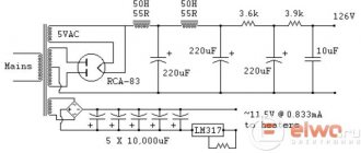
About the power supply. Question. Does a voltage doubling rectifier complicate the power supply?
Answer. It is beneficial to use doubling the voltage in ULF. The doubling circuit does not complicate, but rather simplifies the power supply, because electrolytes are needed for a lower voltage. Domestic USSR capacitors K50-12 150+150 X 250 V are suitable and there is no need to remove excess voltage with a resistor for screen grids, which is worse than taking voltage from electrolytes.
Question. How to use TSSh-170 from a TV to power push-pull 6P14P lamps - about 300V is needed at the anode.
Answer. A rectifier with doubling voltage is connected to the 130 volt secondary winding. After doubling, you get 260 volts. After rectification, the voltage increases by 1.4 times, that is, 260 * 1.4 = 364V, at idle. Under load it will drop to ~300 - 320 volts.
Below are photographs of how to modify the TSSh-170 to use not two anode windings, but all six. Without disassembling the vehicle, lift the outer paper from any edge of the reel. You will see the outer filament windings. Move the side of the frame a little and you will see the underlying anode winding. Pull out the outermost turn (what kind of turn will it be?) to cut it. Next, you measure what you pulled out and what the windings will be like now. Choose any voltage, now even for a fixed bias there will be a winding left.
Note: An amazing example of human resourcefulness and resourcefulness is shown. It remains to ask the question, why all this? The answer may be the result of measuring the no-load current of the TSSh-170 transformer, and not the voltages at all. It is curious that 100% of the measured transformers will give a current of xx 120-200 mA. This is crazy! Why bother with this nonsense? Transformers with a previously known negative result cannot be used in a normal amplifier. These manipulations are shown for very poor, even beggarly people. Citizens, take the TSSh-170 to the trash heap, where they will be picked up and adapted according to the example described. Evgeniy Bortnik
I did an experiment. I soldered the circuit and measured the voltage at XX, and how much it gives under a load of 1.6 kΩ (200 mA). This current is supplied by a rectifier using a doubling circuit.
But even with a standard 130 volt winding, everything is perfect for the amplifier.
Question. In the circuit of a 6P14P push-pull amplifier, if there are two filament windings of a power transformer, how necessary is it to create an artificial ground using two resistors. Just to get away from the background of recess? Or is it possible not to create the earth?
Answer. In a good way, you need to put a tuning resistor of 100 - 300 ohms in the heat of the first lamp of the engine to ground or apply a constant 10-20 volts to the engine. By adjusting the slider, the minimum background is selected. But since the ULF amplification here is no more than 8-12 times, such accuracy is not necessary. You can simply install two resistors (as if the trimmer is in the middle position). If there is one winding, then with low gain, they still make a pseudo-midpoint with resistors. Even at the design and installation stage, it is necessary to avoid those nuances that can increase the background or create excitation of the amplifier. This will save time later on not having to dig around and find out what is causing the background or distortion.
Question. Please draw how to properly organize a fixed bias of the output lamps?
Answer. The pictures are shown below. What is crossed out is better not to do. Although there are plenty of such bias circuits on the Internet and even in industrial equipment. I do the same as on the first two. The reason is that if the tuning resistor fails or the contact on it disappears, the lamp will simply receive a larger bias, but will not get hot and will not fail.
Question. Does it make sense to do a fixed offset or leave the auto offset? Does it only affect the output power?
Answer. Yes, it affects power and low end. Because there is a drop across the cathode resistor. 6P14P has a low push-pull voltage at the cathodes of only 6-7 volts, but in 6P3S at 340 volts 21-24 volts already drop. And in 6P45S already 40-50 volts drop.
Question. Why doesn't anyone make a driver stage with a fixed bias? Enlighten me, and if possible, tell me how to organize it.
Answer. A fixed bias in the output stage is used to increase power and improve efficiency and EVERYTHING! Because the loss of supply voltage at the cathode resistor of the output lamps reduces these indicators, and we also remove the cathode electrolyte in the output stage. What will a fixed offset in the driver do? Nothing! With a fixed bias in the driver, how can you select a mode that minimizes the SOI according to Shmelev? Some “specialists” include a battery or accumulator there. When I changed the bias by 0.1 volt (by the cathode resistor) and the SOI sharply went up. Yesterday I set up the next monoblocks, 0.63 volts turned out to be a bias of 6H9S. What kind of battery or accumulator would you insert there that would give 0.63 volts and the voltage would not change over time?
To be continued.
Evgeniy Bortnik, August 2015, Russia, Krasnoyarsk
↑ First launch
The first launch was successful. There is only one pity: at that time I did not have a multimeter at hand. The old one is broken, I haven't bought a new one yet. In general, I set it up using a barbaric method: I adjusted the offset so that it was minimal, but the anodes did not turn red. Everything seems to be working, it’s time to hide it in the case. And then I was very lucky: an acquaintance of my father gave me an old non-working guitar ULF “Minor”, which was immediately gutted.
The case from “Minor” fit perfectly, two TS180 output transformers (lying) and 2 boards of the ULF itself fit into it, but the TCA-270 power transformer did not fit. Therefore, a separate case was made for the power supply from chipboard and plywood. The top of the body is covered with self-adhesive tape.
Holes for the panels were drilled. Everything is installed, and now the long-awaited launch in the case. I turn it on and... I almost went deaf from the whistle as the lamps warmed up! Cursing, I turn off the power and go to the market to buy a shielded wire, buying it with a reserve.
Amplifier according to the Manakov circuit EL34/6P3S
This well-known circuit of a push-pull tube amplifier based on 6P3S and 6N9S was developed by Anatoly Manakov. See the original here. It is quite simple and with careful assembly it started working immediately without dancing with a tambourine.
I will note right away that some of the denominations I have established differ from those proposed by the author. But this was done not because I conducted long-term auditory experiments with a bunch of Pink Floyd and Led Zeppelin records, but simply because I did not have some capacitors and variable resistors recommended by the developer in my bins. Without further ado, I am not so meticulous about the errors of radio components.
I used triode connection of the output tubes, since the toroidal output transformer does not have additional taps. For lovers of serious and loud sound, it is better to implement pentode connection of output lamps or find recommended transformers. The point is clear: it is advisable to pair the output lamps. The original circuit has a filter capacitor C8, which is not present in my interpretation. I decided to transfer it to the power supply board.
In the voltage rectifier, I used an “electronic choke” on a 12NK90Z field-effect transistor and did not practice with inductors in the form of “iron chokes”. The bias circuit and filament circuits are made identical to the author's version.
I powered each mono amplifier tube from an independent winding, since the toroidal trance has three filament windings. Of great importance in terms of suppressing unwanted noise is the grounding of the filament windings through resistances of 100-150 Ohms to the ground from each arm.
The required power supply voltage is set by selecting resistor Rk. I used the amplifier case as a cooling radiator for the stabilizing transistor VT1, since it heats up quite decently.
Installation of printed circuit boards in a metal case
During installation, special attention must be paid to the bias pattern, which must be negative with respect to ground. The electrolyte banks and the diode bridge should be properly soldered. Otherwise, I think you yourself know the consequences of incorrectly soldered electrolytes in the power supply. I mounted the circuit elements on two functional boards: sound and power supply.
The entire structure fits freely in a standard BO19 aluminum case with dimensions 275/175/65. Printed circuit boards are mounted on posts to the bottom cover. All housing openings through which wires are routed to transformers must be insulated with rubber inserts. Insulating gaskets are placed under the transformers to prevent short-circuiting of the winding to the housing in the event of pushing through the insulation. I placed the input connector on a 6.3 jack, the volume control and the power button on the top panel - for ease of use when placed on the floor. It is better to make a lot of ventilation holes around the holes for the output lamps and the 6n9s driver so that the heat from the ceramic panels also escapes to the top.
There is one caveat in covering transformers with metal caps. The fact is that when the cap is closed to the body through the central bolt, a short-circuited turn is formed. In this case, the amplifier housing will become very hot and interfere with the operation of the transformer. Therefore, it is necessary to use insulating gaskets to secure the caps through the bolt, or to invent other installation options without contact with the body.
Setting the Bias and Anode Voltage for the Driver
Setting up the candy bar is done in silent mode according to Manakov’s recommendations. Of course, an active load in the form of a 4-8 Ohm wirewound resistor of sufficient power (5-10 W) must be connected to the secondary winding of the trans.
Next, the input stage is configured by setting the voltage to 1.8…2 volts at the cathodes of the 6n9s driver. To do this, you need to select the resistance of resistor R4.
Then we adjust the bias voltage for the output stage. Using variable resistors R10 and R12, we set the voltage at the cathodes of the output lamps to 0.035...0.04 volts. Then we apply a signal with a frequency of about 3 kHz and a voltage of 0.5 volts to the grid of the first triode V1. By adjusting the variable resistor R7, we set the same alternating voltage on the anodes V1.
After tuning, the amplifier demonstrated excellent sound quality and a complete absence of extraneous noise. This two-stroke produces a rich and transparent sound with wonderful lows. The triode circuit can provide acceptable volume for a small room of 4x4 meters. Most importantly, you want to listen to such airy sound endlessly, and the volume fades into the background here.
↑ Fighting arousal - shielding
To eliminate self-excitation, which manifests itself as a whistle, it was necessary to shield the grid circuits of the 6N1P triode and the wires in the grid circuits of two 6P36S.
The 6P36S anodes were not shielded. The whistling stopped. I start it up again and hear: one channel works great, but in the other there are clicks instead of bass, plus a sluggish and hoarse midrange. Of course I was upset at this point. And I tried everything, but the reason turned out to be incorrect mesh screening
. The screens were not grounded correctly.
I redid it, grounded the ends of the screens with a star - this is when all the wires go to one point and to the body. The interference and excitement disappeared, the clicks in the bass stopped, the bass became clear, elastic, and both channels began to sing equally beautifully.
Since the 6P36S lamp is prone to self-excitation, if the shielding is poor, a whistle may appear, which indicates a parasitic connection between the input and output of the amplifier. You should try to make the wires as short as possible; the wires carrying the signal should be shielded. In case of self-excitation, which manifests itself as intermittent low-pitched sounds and clicks, it may also be necessary to install anti-excitation resistors in 6P36S grids with a resistance of 0.5-1 kOhm.
The diode bridges in the power supply rectifiers are the same. To a certain extent, this is due to the use of high-capacity storage capacitors in them. In the rectifier, you can use a VD3 diode bridge with a lower current limit value (for example, series
KTs402), but in this case a current-limiting resistor with a resistance of 80 ... 100 Ohms should be connected in series with the winding (5-15).
The fan (it is located on the rear panel of the case - see the layout of units and panels in Fig. 3) for forced ventilation (exhaust) - almost any one from a switching computer power supply, but if possible it is better to choose one with a lower level of acoustic noise.
The power supply uses chokes used in old tube TVs, but you can use others that are suitable for the parameters. The inductance of chokes L1, L2 is 0.4 H, and L3 is 5 H.
Various types of parts can be used in the amplifier: resistors - MLT, MON, BC of appropriate power with a tolerance of no more than 10%; non-polar capacitors - film polyethylene terephthalate K73-9, K73-16 or K73-17 for a voltage of at least 400 V. It is also permissible to install paper capacitors from old equipment - KBG-I, BMT-2, K40U-9, MBM. Oxide capacitors in the power supply and amplifier are imported from Jamicon or domestic series K50-35, K50-26, K50-27.
The signal level indicators in each of the channels (PA1) are arrow (M42305 or similar for 50-200 µA). Basically, they perform an auxiliary function and aesthetically bring some dynamics to the operation of the device. Indicator illumination can be organized using LEDs or miniature incandescent lamps powered by a 12 V voltage source in the power supply.
The amplifier has a unique design. At the bottom there is a power supply mounted on its own chassis; at the top is the amplifier block (two channels), also on a separate chassis (see Fig. 3).
The amplifier uses a volume control with an ALPS RK27 100 kOhm stereo electric motor (Blue Velvet); this allows you to connect a wired remote control, which has one two-pole switch (toggle switch) with three fixed positions (SA1 in the diagram in Fig. 2). Another possible option is a joystick, which, depending on the direction of its deflection, connects the electric drive motor to a 12 V voltage source using bipolar contact groups in the appropriate polarity (you can also use suitable electromagnetic relays, for example, RES22 or similar) * However, remote control not necessarily - this is to a certain extent a tribute to fashion
Particular attention should be paid to the manufacture of the case. Since the amplifier operates in difficult temperature conditions, the wood must first be well dried. In this case, the boards were dried naturally in room conditions for 6 months. After finishing the boards, a body was made from them (photo in Fig. 4). The blanks were cut at the ends at an angle of 45° and glued together with “Joiner-moment” glue. After this, the body was installed near the central heating radiator and covered with a blanket. In this state, it was left to dry for another two months, after which the required holes and windows were cut out and decorative elements of the front, top and rear panels were glued in. After these operations, the body for a month
I dried myself by the radiator again, covered with a blanket. Then it was sanded and painted with the tinting composition “Belinka-TOPLAZUR” in mahogany color (No. 28) in four layers. All this was done so that there would be no surprises in the future when operating the amplifier.
The amplifier has a fairly intense temperature regime in the upper part of the case, while the lower compartment hardly heats up. Insufficiently dried body material (in this case, pine) can burst along the grain. I had to work hard to get a good result: for three years now there have been no complaints about the case. If you don’t want to make bars, the body can be made from plywood 15…20 mm thick, covered with veneer.
The side panels of the case are cut from tinted glass “Turquoise” with a thickness of 5-6 mm. When the amplifier is operating, they can be slightly moved back, as shown in the photo in Fig. 5; while ventilation
hull will improve significantly. To make the life of the amplifier easier, a computer cooler is installed on the rear panel, operating in two modes - at 8 and 12 V. It can be turned on or off if desired
The rear and front panels are cut from 2…3 mm aluminum, sanded and coated with clear acrylic automotive varnish from aerosol packaging.
Holes with a diameter of 5...6 mm are drilled around the lamp panels to ensure natural air convection. The top panel of the case has a protective metal grille, which fits freely into the decorative frame on this panel
In this amplifier model, the output transformers are not quite conventional. They are made on the basis of a TS-90 network transformer with an ShL magnetic core. All windings are removed from the standard coils, and new ones are wound in bulk with a bundle of nine PELSHO wires. Of these, seven PELSHO-0.33 wires are used in the primary winding, and two PELSHO-0.8 wires - in the secondary. The connection diagram of these wires into windings is shown in Fig. 6.
A bundle of these nine wires, about 10 m long, is wound onto the frame of each coil until it is filled (about 70 turns are obtained). Next, these coils are boiled in paraffin for 15...20 minutes in a water bath C
output transformer options are also possible. 6P36S lamps have a fairly low internal resistance, and for a push-pull amplifier using such lamps, from 700 to 1000 turns of the primary winding (for the used magnetic circuit) with a tap from the middle is sufficient.
The amplifier and power supply are equipped with circuit boards made of foil-coated fiberglass. Due to the fact that they have a very simple pattern, it is cut with a cutter made from a hacksaw blade. A view of the installation of small parts and assemblies in the chassis of the blocks is shown in photo fig. 7.
On the rear panel of the case there are output terminals for both channels, input connectors, a remote control connector, a network connector, a fan switch (red key), a fan mode switch - a toggle switch (voltage 8 or 12 V), a case ground terminal and a fuse block (one in the primary network circuit and two in the anode supply circuits of each channel)
From the editor. In the case where the fan is located below powerful lamps, forced ventilation should be organized as supply ventilation.
Author: O. Platonov, Perm (Radio No. 3, 2010)
You may be interested in:
| Radio tubes used in the article:
|
Comments on articles on the site are temporarily disabled due to a huge amount of spam.
↑ Setting and feature of fixed offset
After purchasing the multimeter, the setup became easy, the device is in working order and at hand: resistor R9 set the same voltage on the cathodes of the lamps, and the bias resistor set the voltage to 0.55 Volts.
However, there is one unpleasant feature of a fixed offset. When the network voltage changes, the lamp mode changes. Once the voltage in the network rose to 250 V and one 6P36S went out of mode, the anode became hot, the quiescent current increased to 80 mA (with the prescribed 55 mA)! Fortunately, I noticed this immediately and turned off the ULF. I had to install a voltage stabilizer "Ukraine-3", mine produces 215 V. Due to insufficient voltage on the primary (and, accordingly, on the secondary), the voltages on the anodes dropped from the required 330 V to 313 V. I raised the quiescent current to 64 mA ( drop across resistors R12, R13 = 0.64 V).
So, let's begin
The signal from the sound source is 0.5-0.7V, this is exactly the sensitivity of this amplifier, goes to its input connectors and variable resistor R1, where the sound encounters the first obstacle, yes, that’s right!
After all, even a piece of wire, even a good one, is a barrier that the signal must overcome, and there is nothing to say about a resistor, much less a potentiometer. The quality of operation of the entire amplifier greatly depends on it. Wire-wound resistors are better suited here, but dual 47k wire-wound resistors are very rare in nature, and adjusting the volume with two resistors is not an easy and inconvenient task. The best option is a twin ALPS, but it is quite expensive, although its price is justified at about 1,500 rubles. But I didn’t bother so much and installed a German potentiometer, I bought it on the radio market for a nominal fee, as much as 20 rubles! But it’s okay, I washed it off the dust in alcohol, it doesn’t make any noise at all when turning the handle. Yes, you can talk a lot about every detail, although in high-quality technology there are no trifles... But I won't go off topic. I tried different lamps as a pre-stage lamp, but chose the 6N9S triode; it has a more neutral sound compared to other lamps.
Setting up the cascade consists of setting the voltage at the cathode of the 6N9C lamp within 1.3-1.5 volts by selecting resistor R3. I had to struggle with selecting a resistor; 5-10 Ohms give a deviation of 0.3-0.4V in one direction or another. In the first version, I even made homemade resistors from nichrome, winding nichrome on a rod from a helium pen. But then I abandoned this idea, because I read in one article that it is not advisable to install a wirewound resistor in the first stage of the amplifier, because it has a higher inductance compared to a ceramic one. P1-71, BC, as well as the more common types C2-33N or OMLT are well suited. OMLT resistors have tens of times less noise than MLT.
I used the latter, what was of the required value, because in my case I needed a resistor strictly 500-503 Ohms and 2pcs with an accuracy of 1-2 percent. You shouldn’t skimp on details, especially when you get a good return on your investment. I first used a 560 μF tantalum K73-9 capacitor C4 - it costs 1,500 rubles, but I got it for free. Then I read that tantalum is not well suited for audio circuits, but is better suited for power supply, since it has less resistance at HF. I compared the sound of a tantalum capacitor and a Jamicon 1000uF electrolyte, concluded that Jamicon was better and left it. Tantalum had to be postponed until better times, because it is 16V, and in this amplifier there is no such voltage anywhere else, much less in the power supply - 300V! I bypassed C4 with a 2.2 µF capacitor, as in the circuit, with an imported film MKT, I couldn’t find a better one. It's better to install Epcoc or MBGO. I didn’t install MBGO, since it takes up too much space, and I immediately decided that I would collect the displacement of the first stage on the p/p, and let the Hi-End connoisseurs scold me.
But in the C3 coupling capacitor I used Jensen Audio with aluminum foil at 0.68 µF 400V, what was left of the coupling filters in my homemade speakers =). Now such a capacitor costs about 1,500 rubles. I tried different capacitors, but settled on these ones. Next comes resistor R6 for 200k. You can experiment with it by changing the lower pass frequency of the amplifier. I will give a formula for calculating the separating capacitor. C=159/F*R, where C is the capacitance in uF, F is the lower limit frequency in Hz, R is the resistor in the control grid of the next (output) lamp in kOhm. As you can see, the calculation is very simple and allows you various variations. Electrolytic filter capacitors in power supply circuits can be simpler. I used Jamicon, shunting with imported mica, unfortunately, I don’t know the brand. K73 can be used; K77.
In auto bias - R8 500ohm 4W, but this power is clearly not enough, it heats up to 80 degrees, and this is unacceptable, since it begins to make noise even more at this temperature. A 10 watt resistor is suitable here! It sets the lamp current. Wire type PEV-10. But I didn’t find it at 500 Ohm. What I've done? I took a 5W resistor and made a radiator for it from thin steel and a sheet of aluminum, thus increasing the power dissipation, I think watts to 20. I used a Jamicon capacitor C7 and shunted it with a 2.2 uF Epcos capacitor. Resistor R7 can be safely set to 2W, it hardly heats up. It is only important to select it so that there is slightly more voltage at the lamp anode than at the second grid. I used a TW6SE for the output transformer, although a TVZ-1-9 will also work in this amplifier. An important condition is its coordination with the load. There were no problems with the TW6SE - it has a winding output for 4-6-8 Ohms. I placed 2 output transformers on top of the amplifier, under a closed aluminum casing.
It is advisable to use a 5Ts3S kenotron (5Ts4S, 5U4G) for the power supply. The use of kenotron power, compared to diodes, makes the amplifier sound warmer and more coherent. I used a diode bridge on ultra-fast diodes, shunting each with a 220nF capacitor. I used the following power transformers: - a 400W toroidal type power transformer, it has 4 output windings of 125V each - this allows it to power both a 250V diode bridge and a kenotron, if available;
- the second transformer is also toroidal, but with a power of about 40-50W. It powers the filament of all lamps. The main condition of this transformer is the ability to supply a current of 4A to the load for incandescent lamps and 2A in the case of kenotron power supply. Also, from this transformer I powered the anode power soft-start circuit to extend the life of the lamps and provided a 50V winding for the possibility of connecting a fixed bias. Chokes can be used DR-2LM, DR-2.3-0.2 from black and white TVs, unified D 21, D 31. I used homemade chokes wound on toroidal transformers with a cut core, each containing 1000 turns of PEV wire - 0.33 and has an active resistance of 19 Ohms.
The amplifier is mounted using a hinged method; the leads of the parts themselves and the contacts of the lamp panels are used to the maximum. The ground bus is made of single-core copper wire with a diameter of 2 mm and has contact with the chassis at one point, next to the input. The wires going to the filament terminals of all lamps must be intertwined with each other. This is necessary to reduce the background alternating current. Resistors R9-R12 also serve the same purpose. As connecting wires, I used silver-plated MP-0.5 wire in fluoroplastic insulation.
In conclusion, I want to say that this amplifier is not just a circuit, but a really manufactured and well-proven device. I've been using it for about three months now and am very pleased with its sound. For those who think that 4 W per channel is not enough, I will say that in a room of 16 square meters when using KEF Q1 acoustics (sensitivity 91 dB), the amplifier develops sound pressure comparable to the sound pressure developed by a transistor amplifier with a power of 40 W per channel (these are the results of a subjective assessment of my musician friends). But the sound is different.
The amplifier perfectly senses the slightest nuances of the sound of instruments or voices and seems to “breathe” (forgive me if the comparison is not very correct). The sound does not tire him, you want to listen to him and listen to him.
↑ Total
After tuning, the amplifier was painted matte black to restore the shabby exterior.
I was pleasantly surprised by the sound of this amplifier. I only listen to rock, so when comparing I only included that. The signal source is a computer with a Sound Blaster Audigy sound card, and the output is a 3-way AIWA SXNH3 speaker. The amplifier sounds very beautiful: ringing, clear midrange; not clicking, distinct high frequencies; awesome soft elastic bass. I compared it with SE on 6F5P and SE on 6P14P. I undoubtedly like my two-stroke 6P36S better.
Tube amplifier PP for 6P36S and 6N23P
Good afternoon Once upon a time, when I was on my own, I assembled a tube amplifier using the common 6p14p SE circuit. But, because I was single and without children, so the amplifier turned out to be a snot, there were only lamps attached to the chassis, the output transformers stood nearby, and the power supply was generally assembled by hanging mounting and dumped in a box. Accordingly, the sound matched the installation: it was loud, one channel was louder (and the background was stronger), the other channel disappeared until you hit the case, and the look was the same. But time goes by, everyone changes, including me. I got married, settled down, had a child, and lost my free time and money for radio hobbies. And the desire to collect something only intensified. I decided that this amplifier had already outlived its usefulness and I needed to make something decent so that I could put it on a shelf, connect a vinyl turntable with an old jazz record to it and sit pleasantly with cognac and a good book. But there was no time or money for good and beautiful parts, so I collected from what I had.
I took as a basis the circuit of a PP amplifier using 6P36S tubes with a 6N23P driver, because 6P36S cost 10 rubles on our market. The diagram seems simple and understandable, so I assembled it using hanging installation in a few days. I assembled the power supply using a TS-180, took the chokes from a computer power supply at work, and took the outputs from a TAN-104. I picked out filter capacitors from computer power supplies, fortunately there were plenty of burnt ones at work.
I want to warn you right away that I assembled it slowly, there were two main reasons: I had free time only late in the evening (if I had any energy left), an hour before bed, and the lack of parts at hand. After moving to a new apartment, all my supplies remained at my old place of residence, with my parents in a private house.
After assembling the amplifier and checking its operation, the main problem was the housing. I thought for a long time about what to come up with for the case, until one box caught my eye. I remembered that kitchen assemblers brought fittings in this box, so the box was assembled somehow, but, most importantly, the dimensions of the walls (length and height) were the same. I smashed the box, assembled it in a good way and got a normal case, into which both outlets fit while lying down and the power supply could fit into it while standing. I cut out the top cover from the wall of an old system unit (at work I somehow found an old system unit with thick iron). I decided to cover the power supply trans with chokes with the body of a computer power supply unit, having previously cut a hole in it. I cut all the holes in the iron myself, using metal scissors. I drilled crooked holes for the lamps, but under the lamps this crookedness is not visible, and it does not affect the sound :).
I wanted to add different colors to my brainchild, so I took an RGB LED strip I had saved up from a long time ago, picked out LEDs from it (there are three colors in one housing) and put them on glue in the holes in the lamp panels. So that you can change colors depending on your mood, there are three toggle switches on the back, for each color.The body was cleaned and painted with automotive paint. But it was necessary to immediately coat it with varnish, otherwise chips have now appeared and it needs to be repainted.
I assembled the case, assembled the amplifier, adjusted the anode current and was surprised! I was surprised by the purity of the sound, the presence of bass (this is on TANs) and the lack of background. To be honest, I didn’t expect it, because it was assembled on my knees.
What makes me most happy is the amount I invested in it:
— Lamps: 80 rubles (2x6N23P for 10 rubles + 8x6P36S - bought 8 pieces for 60 rubles, chose the best); — Panels for lamps: 100 rubles for everything; — Audio input-output panels: 30 rubles: — Toggle switches for LEDs: 30 rubles; — Volume knob: 30 rubles; — Parts (several resistors + interstage capacitors): 100 rubles.
Total for only 370 rubles. The rest is my own, including the paint (I don’t remember why I bought it). Now the amplifier is standing and makes me happy in the evenings with its sound and appearance (especially in the dark). And a vinyl turntable is slowly being prepared for it...