The audio range covers frequencies from 20 Hz to 20 kHz. A person with normal hearing can perceive these vibrations. In hi-and systems, the reproduced frequency band can be expanded from 15 Hz to 40 kHz. These systems have complex design solutions. Simple circuits that provide satisfactory sound quality can be assembled on your own. The audio amplifier circuit, which is not difficult to make with your own hands, does not contain scarce parts and is available for repetition. Such a circuit can provide a frequency band within the range of 50 Hz-15 kHz with a nonlinear distortion coefficient of no more than 0.1% and provide an output power of 10-15 watts to a low-impedance load. You can assemble a sound amplifier circuit using both transistors and integrated circuits.
Stereo sound amplifier on TDA7262
Hi-Fi amplifier for two channels.
This microcircuit has a wide supply voltage range, and the output current reaches 3.5 amperes. A standby function and protection against short circuits and overheating during operation are also available.
Limit characteristics of the microcircuit
| Supply voltage Upit | 25 V |
| Output peak current | 4.5 A |
| Power dissipation Prass | 30 W |
| Working temperature Trab | -20…+85 °C |
What is a black box in electronics
In general, an amplifier can be viewed as a black box.
What is this black box? This is a box. He's black). And since it is black, absolutely no one knows what is in it. We can only guess. But it is also possible that we can take some action and wait for a response. After the response of this black box, we can guess what is inside it.
That is, in essence, a black box must have some “sensors” for perceiving information from the outside, some “input”, as well as some “output” for a response. That is, by applying any influence to the input, we wait for the response of the black box at the output.
Let there be a cat or cat in the black box, but so far no one knows that he/she is there. What will we do first? Let's shake the box or kick it, right? If someone meows there, it means it’s definitely either a cat or a male cat). That is, there was a response. How to determine further whether it is a cat or a male cat? We open the box, and a shaggy miracle crawls out of it. If it runs, it means it's a cat. If it runs, it means it’s a cat).
But there can also be absolutely any body or substance in the black box. For such situations, we must conduct as many experiments as possible, that is, produce as many input influences as possible to more accurately determine the contents of the black box.
Amplifier 50 W
A simple single-channel circuit based on TDA1514.
Chip characteristics
| Parameter | Meaning |
| Upit1 | +10…+30 V |
| Upit2 | -10…-30 V |
| Iout | 5 A |
| Irest | 56 mA |
| Pout | 50 W |
| Rin | 20 kOhm |
| Gain | 30 dB |
| Frequency band | 20-25,000 Hz |
| Harmonic distortion | 0,01 % |
| Rload | 8 ohm |
Pin assignment
| Pin number | Purpose |
| 1 | Non-inverting input |
| 2 | Protection circuit output |
| 3 | Supply Voltage Shutdown Circuit Output |
| 4 | Supply voltage (-27.5 V) |
| 5 | Exit |
| 6 | Supply voltage (+27.5 V) |
| 7 | Power amplifier feedback and correction input |
| 8 | Output shutdown circuit output |
| 9 | Inverting input |
TDA8567q 4x25 W
Hi-Fi class bridge amplifier for four channels.
There is protection against short circuit of the output stage and thermal protection with a reduction in output power when overheated. The microcircuit also has protection against voltage fluctuations and a shutdown mode. This microcircuit also has an on/off mode for the input signal (Mute mode), and protection against “clicking” when voltage is applied to the circuit.
Chip characteristics
| Parameter | Meaning |
| Upit | 6-18 V |
| Iout | 7.5 A |
| Irest | 230 mA |
| Pout | 4x25 W |
| Rin | 30 kOhm |
| Gain | 26 dB |
| Frequency band | 20-20000 Hz |
| Harmonic distortion | 0,05 % |
| Rload | 4 ohm |
Pin assignment
| Pin number | Purpose |
| 1 | Supply voltage |
| 2 | Exit 1+ |
| 3 | General |
| 4 | Output 1- |
| 5 | Output 2- |
| 6 | General |
| 7 | Exit 2+ |
| 8 | Supply voltage |
| 9 | Diagnostics |
| 10 | Input 1 |
| 11 | Entrance 2 |
| 12 | General signal |
| 13 | Entrance 3 |
| 14 | Entrance 4 |
| 15 | Mode selection |
| 16 | Supply voltage |
| 17 | Exit 3+ |
| 18 | General |
| 19 | Output 3- |
| 20 | Output 4- |
| 21 | General |
| 22 | Exit 4+ |
| 23 | Supply voltage |
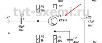
Operating point and base offset
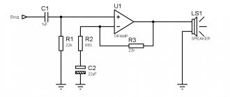
To ensure that the transistor does not distort the input signal, you first need to open it slightly.
This can be done using a voltage divider consisting of two resistors R1 and R2. This voltage divider allows you to slightly open the transistor VT1 so that the input signal does not waste its electrical energy on its opening.
The current that flows through R1 and R2 goes to the base of transistor VT1, which then goes through the emitter, thereby opening it. This is called the base bias of the transistor, that is, its opening. The bias voltage determines the operating point. In this case, a class A amplifier.
How is the amplifier class determined?
The class of an amplifier is determined by its operating point. The operating point is selected using the current-voltage characteristic of the transistor. The higher the voltage applied to the transistor input, the greater the current, the higher the operating point.
For example, the point in the center is class A.
And the class is the highest quality of amplifiers. It amplifies both the positive and negative half-waves of the input signal. At the same time, this class has a significant drawback. This limits power and reduces energy efficiency. The fact is that as long as no input signal is received at the ULF input, it works all the time while it is turned on.
It turns out that this wastes excess electricity. Therefore, the operating point is also called the resting point, when the amplifier does not amplify the input signal.
The sensitivity of the amplifier also depends on the operating point.
There are also class B, AB and D. They differ from each other in amplification efficiency and the presence of distortion. It all depends on the scheme used.
For example. Class D does not open the transistor at all, but from the point of view of energy efficiency it is the best choice. The transistor does not consume anything at rest; it turns on only when an input signal is applied. And at the same time, if an analog audio signal is supplied to the input, it is distorted. Such a class will not be suitable for the scheme that we are analyzing in this article.
Therefore, circuit designers and engineers invented digital amplifiers. Their analog signal is converted to digital, and only then fed to the input of the amplifier. The transistor does not distort the signal with the input digit. After amplification, the signal is again converted to analog with the least loss and distortion.
And the AB mode is used in circuits where there are several transistors that operate at their own half-waves. There are circuits where one transistor amplifies only positive half-waves, and the second only negative ones. Such amplifiers are called push-pull.
Stereo amplifier 12 dB
The TDA8199 can be used with both electronic volume controls and simple potentiometers of the appropriate sound class.
Characteristics
| Supply voltage Upit | 10.8 - 13.2 V |
| Current consumption Ipotr | 21 - 28 mA |
| Gain output/input | 12 dB |
| Audio input impedance Rin | 22 - 1000 Ohm |
| Harmonic coefficient Kr | 0,35 — 1 % |
| Audio output impedance Rout | 30 - 1000 Ohm |
| Output noise voltage Uout noise | 30 µV |
Chip Limits
| Supply voltage Upit | 16 V |
| Working temperature Trab | -55…+125 °C |
| Storage temperature | 0…+70 °C |
ULF TDA8198 12 dB
The TDA8198 chip is manufactured in a DIP14 package and is used in high-end equipment.
The dynamic signal level is 90 dB.
There is protection of the output stage from short-circuit and static.
Chip characteristics
| Supply voltage Upit | 10.8 - 13.2 V |
| Current consumption Ipotr | 24 - 32 mA |
| Reference voltage Uref | 6.9 V |
| Output noise voltage Uout noise | 300 µV |
| Harmonic coefficient Kr | 0,3 — 1 % |
| Audio input impedance Rin | 22 kOhm |
| Audio output impedance Rout | 10 - 300 Ohm |
Chip Limits
| Supply voltage Upit | 16 V |
| Working temperature Trab | -55…+125 °C |
| Storage temperature | 0…+70 °C |
ULF TDA8196 12 dB
A simple power amplifier circuit using TDA8196. Scheme for a beginner radio amateur. Doesn't require many parts and is easy to assemble. Miniature bridge low frequency power amplifier with electronic volume control.
There is protection for the output stage against short circuits and thermal protection against overloads. And of course, protection against static. The amplifier can be adjusted either with a potentiometer or with a simple electronic volume control.
Specifications of TDA8196
| Supply voltage Upit | 10.8 - 13.2 V |
| Current consumption Ipotr | 12 mA |
| Reference voltage Uref | 6.6 V |
| Audio input impedance | 10 - 13 kOhm |
| Audio input impedance | 0.2 - 1 kOhm |
| Harmonic coefficient Kr | 0,4 — 1 % |
| Output noise voltage | 40 µV |
Chip Limits
| Supply voltage Upit | 16 V |
| Working temperature Trab | -55…+125 °C |
| Storage temperature | 0…+70 °C |
New powerful Hi-Fi class ULFs NM2042 and NM2043
Ganichev G. Moscow
This article continues a series of publications devoted to power amplifiers offered to radio amateurs by MASTER KIT. The article includes two recent developments - NM2042 (powerful low-frequency amplifier 140 W) and NM2043 (powerful automotive bridge Hi-Fi low-frequency amplifier 4x77 W). The amplifiers are designed taking into account all the necessary requirements and are made on a modern integrated element base. The offered PAs have high performance characteristics, high reliability, ease of manufacture/connection and an optimal price/quality ratio, which is an important factor today. You can assemble the devices from the MASTER KIT kits NM2042 and NM2043.
MASTER KIT specialists were given, and successfully solved, the task of preparing technical documentation and producing a line of ULFs for use in Hi-Fi audio equipment. Gradually, the range of these devices is expanded and supplemented with new developments. This article will look at two new developments - NM2042 and NM2043.
All proposed models of power amplifiers have a minimum level of self-noise, a minimum level of nonlinear distortion and a wide reproducible frequency band. Models differ mainly in maximum output power, supply voltage (bipolar or unipolar “automotive” (14.4 V)), number of amplification channels and external design.
Radio amateurs can wire a printed circuit board themselves, but it must be taken into account that this is a very responsible and serious job. Not everyone knows that, for example, incorrect routing of printed conductors in a powerful amplifier can increase the level of its nonlinear distortion tenfold or even render it inoperable altogether. Therefore, professional designers specializing in this field were involved in the development of printed circuit boards.
NM2042. Powerful low frequency amplifier 140 W (TDA7293).
The proposed low-frequency amplifier has a minimum nonlinear distortion coefficient and noise level. The device has small dimensions. A wide range of supply voltages and load resistances expands the scope of application of this PA. It can be used both outdoors for various events and at home as part of your musical audio complex. The amplifier has proven itself well as a ULF for a subwoofer.
The ULF is made on the TDA7293 integrated circuit. This IC is a class AB ULF. Thanks to a wide range of supply voltages and the ability to deliver current to a load of up to 10 A, the microcircuit provides the same maximum output power at loads from 4 Ohms to 8 Ohms. One of the main features of this microcircuit is the use of field-effect transistors in the preliminary and output amplification stages and the ability to parallel connect several ICs to operate with low-impedance loads (< 4 ohms).
The operating mode of the IC is controlled using switch SW1. To turn on the ULF, SW1 must be closed. Switch SW2 is provided for technological purposes. For normal operation, SW2 must be jumpered in position 2-3.
Coil L1 must be made independently. L1 – frameless, three-layer, contains ten turns of PEV-1.0 wire in each layer. Winding must be carried out on a 12 mm mandrel. Approximate inductance – 5 µH.
The supply voltage is supplied to contacts X3 (+), X6 (-) and X7 (common).
The signal source is connected to X1(+) and X2(common).
The load is connected to X4(+) and X5(common).
Structurally, the amplifier is made on a printed circuit board made of foil fiberglass. The design provides for installation of the board into the case; for this purpose, mounting holes are provided along the edges of the board for 2.5 mm screws. For the convenience of connecting the supply voltage, signal source and load, the board has reserved spaces for terminal screw clamps.
Structurally, a dual logical input of control signals MUTE/ST-BY is provided for “soft” activation of the ULF.
The amplifier chip must be installed on a heat sink (not included in the kit) with an area of at least 600 cm2. As a radiator, you can use the metal case or chassis of the device into which the ULF is installed. During installation, it is recommended to use heat-conducting paste type KTP-8 to increase the reliability of the IC.
The general view of the amplifier is shown in Fig. 1, the electrical circuit diagram in Fig. 2, the arrangement of elements on the board and the connection of the amplifier in Fig. 3, the view of the printed circuit board from the side of the conductors in Fig. 4. The list of elements is given in Table 2.
Table 1. Technical characteristics.
| Supply voltage, bipolar, V | +/- 12…50 |
| Peak output current, A | 10 |
| Current in quiescent mode, mA | 30 |
| Current in MUTE/ST-BY mode, mA | 0,5 |
| Output power, W at harmonic distortion = 1%, Up = +/- 30 V, Rн = 4 Ohm | 80 |
| Output power, W at harmonic distortion = 10%, Up = +/- 45 V, Rн = 8 Ohm | 140 |
| Output power, W at harmonic distortion = 10%, Up = +/- 30 V, Rн = 4 Ohm | 110 |
| Gain Au, dB | 30 |
| Reproducible frequency range, Hz | 20…20000 |
| Input impedance, kOhm | 22 |
| PCB dimensions, mm | 47x55 |
Table 2. List of elements.
| Position | Name | Col. |
| C1 | 470 pF | 1 |
| C2 | 0.47 µF | 1 |
| C3, C10 | 22 µF/63 V | 2 |
| C4, C5 | 10 µF/63 V | 2 |
| C6, C7, C11 | 0.1 µF | 3 |
| C8, C9 | 1000 µF/63 V | 2 |
| DA1 | TDA7293 | 1 |
| L1 | 5 µH | 1 |
| R1 | 1 kOhm | 1 |
| R2 | 10 kOhm | 1 |
| R3 | 30 kOhm | 1 |
| R4, R5, R9…R12 | 22 kOhm | 6 |
| R6 | 20 kOhm | 1 |
| R7 | 680 Ohm | 1 |
| R8, R14 | 4.7 ohm | 2 |
| R13 | 270 Ohm | 1 |
| VD1 | 1N4148 | 1 |
Fig1. General view of the NM2042 amplifier.
Fig.2. Electrical circuit diagram of the NM2042 amplifier.
Fig.3. Layout of elements on the board and connection of the NM2042 amplifier.
Fig.4. View of the printed circuit board from the side of the printed conductors of the NM2042 amplifier.
NM2043. Powerful car bridge Hi-Fi low frequency amplifier 4X77 W (TDA7560).
The main purpose of this ULF is to install it in your car radio, instead of an old low-frequency amplifier, to increase its output power or for outdoor events using a 12 V battery as the main power source for the equipment. Thanks to the use of a bridge circuit, the amplifier develops power up to 80 W into a 2 Ohm load in each of the four channels. A special feature of the amplifier is the use of field-effect transistors in the output stages. The device has small dimensions, a wide range of supply voltages and load resistances.
The ULF is made on an integrated circuit TDA7560 (DA1). This IC is a class AB ULF and is installed in car audio devices to obtain a high-quality, powerful output music signal. The IC is designed to operate with a load of 4...2 Ohms, signal distortion meets Hi-Fi requirements. The microcircuit has protection against short-circuit load and overheating. Features of the microcircuit include the use of field-effect transistors in the output stages. The microcircuit contains four identical bridge amplifiers with a power of up to 80 W into a 2 Ohm load.
Switches SW1 (ST-BY) and SW2 (MUTE) are designed to control the operating modes of the IC. Closing the contacts in SW1 controls the ST-BY (standby/working) mode, and SW2 controls the MUTE (pause) mode.
Particular attention should be paid to connecting the microcircuit to the power source:
The IC is extremely sensitive to supply voltage - a maximum of 18 V.
Reversing the polarity of the supply voltage source leads to failure of the IC (Urev = 6 V maximum).
The supply voltage is connected to contacts X9(+) and X10(-).
Signal sources are connected to X1(+),X2(-);X3(+),X4(-);X5(+),X6(-);X7(+),X8(-).
The amplified signal is removed from contacts X11, X12; X13, X14; X15, X16; X17, X18.
The general view of the amplifier is shown in Fig. 5, the electrical circuit diagram in Fig. 6, the arrangement of elements on the board and the connection of the amplifier in Fig. 7, the top view of the printed circuit board in Fig. 8, the bottom view of the printed circuit board in Fig. 9. The list of elements is given in Table 3.
Table 3. Technical characteristics.
| Supply voltage, V | 6…18, typical 14.4 V |
| Peak output current, A | 10 |
| Current in quiescent mode, mA | 200 |
| Maximum output power, W at Up = 14.4 V and Rн = 4 Ohm | 50 |
| Maximum output power, W at Up = 14.4 V and Rн = 2 Ohm | 80 |
| Voltage gain Au, dB | 26 |
| Reproducible frequency range, Hz | 20…20000 |
| Input impedance, kOhm | 100 |
| PCB dimensions, mm | 51x50 |
Table 4. List of elements
| Position | Name | Col. |
| C1, C6…C10 | 0.1 µF | 6 |
| C2…C5 | 470 pF | 4 |
| C11 | 200 µF/25 V | 1 |
| C12…C14 | 0.47 µF | 3 |
| C15 | 47 µF/25 V | 1 |
| DA1 | TDA7560 | 1 |
| R1…R4 | 1 kOhm | 4 |
| R5 | 10 kOhm | 1 |
| R6 | 47 kOhm | 1 |
Fig.5. General view of the NM2043 amplifier.
Fig.6. Electrical circuit diagram of the NM2043 amplifier.
Fig.7. Layout of elements on the board and connection of the NM2043 amplifier.
Fig.8. Top view of the printed circuit board of the NM2043 amplifier.
Fig.9. Bottom view of the printed circuit board of the NM2043 amplifier.
CONCLUSION
To save time and relieve you from the routine work of finding the necessary components and making printed circuit boards, MASTER KIT offers the NM2042 and NM2043 kits. Each kit consists of a factory printed circuit board, all necessary components and instructions for assembly and operation.
The material was published in the magazine Radio Amateur 2003`10.
NM2042
Mono bass amplifier, 140 W, class AB (TDA7293) - soldering kit
1 790
NM2043
Kit for assembling a bass amplifier 4 x 77W (TDA7560)
1 550
TDA7265 and two inclusion options
There are two options for turning on the microcircuit.
- Large power range (+-25V);
- Bipolar power supply circuit;
- Power 2x25 W
- There is a silent mode and a standby function;
- Thermal protection against overheating during amplifier operation;
- There is short-circuit protection.
Bridge version of the amplifier on TDA7265
Chip characteristics
| Supply voltage Upit | 25 V |
| Output voltage in idle mode | 80 - 130 mV |
| Current consumption in idle mode Ipotr | 65 - 120 mA |
| Bias current at the non-inverting input Ibias | 500 nA |
| Output power Pout | 20 - 25 W |
| Harmonic coefficient Kr | 0,01 — 0,7 % |
| Gain (Open Loop) | 80 dB |
| Input resistance Rin | 15 - 20 kOhm |
| Shutdown temperature | 145 °C |
Limit parameters of the microcircuit
| Supply voltage Upit | 25 V |
| Output peak current | 4.5 A |
| Power dissipation Prass | 30 W |
| Operating temperature Trab | -20…+85 °C |
| Storage temperature Tstore | -40…+150 °C |
Stabilization of the circuit operation
When a semiconductor heats up, its resistance decreases. The transistor is made of a semiconductor, and accordingly its pn junctions are too.
When the ULF circuit operates, current flows through the transistor and it heats up. Typically all power is dissipated at the collector. Nevertheless, the characteristics of the transistor change dramatically, since the resistance of its pn junction decreases sharply as the temperature rises.
To stabilize the operation of the transistor, you need to balance its resistance with another source. This can be done using additional resistance.
When the resistance of transistor VT1 decreases, resistor R3 takes part of the voltage onto itself and does not allow the current in the circuit to increase.
Thanks to this, the transistor:
- does not close;
- does not go into saturation mode;
- does not distort the signal;
- and doesn't overheat.
This is called thermal stabilization of the amplifier.
And so that in normal operation, when VT1 does not heat up, resistor R3 does not reduce the power of the circuit, a shunt electrolytic capacitor C2 is included in the circuit. The variable component of the input signal passes through it without loss.
Bridge to TDA7240
A miniature but quite powerful low-frequency power amplifier, made using a bridge circuit.
The amplifier has:
- Protection of the output stage from short circuit;
- Thermal protection in case of overload;
- Reliable protection against surges up to 28 V.
Chip characteristics
| Upit | 6 - 18 V |
| Iout max | 4.5 A |
| Irest | 150 mA |
| Pout | 20 W |
| Rin | 50 kOhm |
| Gain | 40 dB |
| Frequency band | 30 - 25 kHz |
| Harmonic distortion | 0,5 % |
| Rload | 4 ohm |
Pin assignment
| Pin number | Purpose |
| 1 | Distortion Compensation Circuit Output |
| 2 | Output of correction scheme |
| 3 | Entrance |
| 4 | General |
| 5 | Output 1 |
| 6 | Supply voltage |
| 7 | Exit 2 |
Types of amplifiers by bandwidth
Based on bandwidth, amplifiers are divided into:
Low Frequency Amplifiers
They are also called audio frequency amplifiers (AF). They are designed to amplify signals with frequencies from tens of Hertz to 20 kHz. 20 kHz is the limit of frequency that can be perceived by the human ear. Therefore, this type of amplifier is very popular among music lovers and radio amateurs.
High frequency amplifiers
They are designed to amplify signals over the entire range of frequencies used by electronics.
Broadband amplifiers
They allow amplification of a wide frequency band (for example, from tens of hertz to several megahertz). Here, I think, everything is clear.
Narrowband amplifiers
They amplify a narrow frequency band. These can be resonant filters, as well as filters that are based on UHF and ULF.
ULF circuit on TDA7236
The microcircuit is in a minidip (4+4) package.
Chip characteristics
| Supply voltage Upit | 1.8 - 24 V |
| Current consumption with idle mode Ipotr | 5 mA |
| Output power Pout | 1.7 W |
| Harmonic coefficient Kr | 0,3 — 1 % |
| Gain (closed loop) | 38 dB |
| Input resistance Rin | 100 kOhm |
Limit parameters
| Supply voltage Upit | 28 V |
| Output current Iout | 1 A |
| Power dissipation Pdis | 500 mW (SZIP package), 800 mW (SSOP package) |
| Temperature Tb | 40…+150 °C |
Amplifier operating class
As is known, depending on the degree of continuity of current flow during its period through a transistor amplifier stage (amplifier), the following classes of its operation are distinguished: “A”, “B”, “AB”, “C”, “D”.
In operating class, current “A” flows through the cascade for 100% of the input signal period. The operation of the cascade in this class is illustrated by the following figure.
In the operating class of the amplifier stage “AB”, the current flows through it for more than 50%, but less than 100% of the input signal period (see figure below).
In the “B” stage operation class, the current flows through it for exactly 50% of the input signal period, as illustrated in the figure.
And finally, in the “C” stage operation class, the current flows through it for less than 50% of the input signal period.
Amplifier based on TDA7052
Used in portable audio equipment
An amplifier assembled according to this scheme has a number of advantages:
- No external elements needed;
- Minimal interference when turning on and off;
- Sufficiently high stability of operation when amplified;
- Low power consumption;
- No need for an additional radiator
- There is short-circuit protection.
Chip characteristics
| Supply voltage Upit | 3 - 18 V |
| Current consumption in idle mode Ipotr | 4 - 8 mA |
| Gain factor Kusil | 38 - 40 dB |
| output power | 1.2 W |
| Harmonic coefficient Kr | 0,2 — 1 % |
The presence of distortion in various classes of low-frequency amplifiers
The working area of a class “A” transistor amplifier is characterized by fairly small nonlinear distortions. If the incoming signal spits out higher voltage pulses, this causes the transistors to become saturated. In the output signal, higher ones begin to appear near each harmonic (up to 10 or 11). Because of this, a metallic sound appears, characteristic only of transistor amplifiers.
If the power supply is unstable, the output signal will be modeled in amplitude near the network frequency. The sound will become harsher on the left side of the frequency response. But the better the stabilization of the amplifier's power supply, the more complex the design of the entire device becomes. ULFs operating in class “A” have a relatively low efficiency - less than 20%. The reason is that the transistor is constantly open and current flows through it constantly.
To increase (albeit slightly) efficiency, you can use push-pull circuits. One drawback is that the half-waves of the output signal become asymmetrical. If you transfer from class “A” to “AB”, nonlinear distortions will increase by 3-4 times. But the efficiency of the entire device circuit will still increase. ULF classes “AB” and “B” characterize the increase in distortion as the signal level at the input decreases. But even if you turn up the volume, this will not help completely get rid of the shortcomings.
A pair of amplifiers on the TDA7050 chip
The supply voltage is only 1.6 V and this circuit is excellent for operation on batteries and rechargeable batteries.
The circuits are simple enough to be assembled by novice radio amateurs. It can also be assembled on a breadboard.
Bridge version of the microcircuit amplifier
Advantages of the microcircuit:
- A small number of external elements necessary for the operation of the microcircuit;
- Low current consumption;
- Gain 26 dB;
- Floating differential input;
- The chip has stereo and bridge modes.
Chip characteristics
| Supply voltage (Upit) | 1.6 - 6 V |
| Current consumption in idle mode (I consumption) | 3.2 mA |
| Output power in bridge mode | 140 mW |
| Output power in stereo mode | 75 mW |
| Channel Separation | 40 dB |
Source of schematics
S. R. Bashirov, A. S. Bashirov Modern integrated amplifiers