Good afternoon everyone! In this review I will show the result of a slightly protracted project that was started 4 years ago, but resumed and completed within the last 2 months. As is often the case with radio amateurs, assembled and debugged device boards move into a drawer/box and do not find their rightful place as ready-to-use devices. This time I managed to gather my strength and put the necessary components into an original case, resulting in a high-quality multimedia device that, I hope, will function successfully and please the ear for a long time. In the review, I will show all the main points of manufacturing the case and assembling the device, share diagrams of self-assembled components, as well as links to purchased components.
INTRODUCTION.
I always wanted to have a more or less serious UMZCH, but in the list of life priorities it always fell to the bottom.
An alternative option was to assemble the device yourself, but I was deterred by the lack of skills to work properly with a soldering iron and the need to make a beautiful case, which I had absolutely no confidence in. The impetus for action for me was a whole series of articles “Complete amplifier on microcircuits” by Vladimir Mosyagin (MVV) in the Journal of Practical Electronics “Datagor” (link) [Complete amplifier on microcircuits. Part 1. Audio power amplifier on TDA2006, TDA2030, TDA2040, TDA2050, LM1875 I actually read a lot of articles for beginners on the basics of building ULFs, power supplies, switching, and manufacturing printed circuit boards. Then I went to Igor Rogov’s resource (Audiokiller) (link) and also read his book “Design of power supplies for audio amplifiers”
After reading everything in different sources, I realized that not everything is so scary and quite doable. Perhaps not everything will work out the first time, but still, something worthwhile should come out.
The following requirements were formulated for the final device: - presence of amplification channels for stereo speakers (SOLO-3 for now) and a separate subwoofer; — the ability to connect external signal sources, as well as the use of a permanent built-in source in the form of a Raspberry Pi, the ability to conveniently switch between sources; — expanded multimedia capabilities, connecting to TV via HDMI, watching video from a home server; — compact, laconic, pleasing to the eye device body;
Amplifier Center - Power
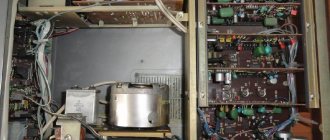
The most important thing in audio signal amplifiers is the power supply. For audio amplifier devices, only specialized power supplies are used.
The main requirements for them will be the absence of vibrations, pulsations and electromagnetic radiation. In this regard, the class of power supplies for sound amplifiers must be very high, even in the case of the weakest models.
Read here - Design of a small dressing room - choosing a location, design, layout, 110 photos of the best design projects
When creating not only sound amplifiers, but also any other equipment in audio format, pulse blocks are not used.
Here it is easier to give preference to transformer models that meet the class requirements. Pulsed ones create high electromagnetic frequencies, from which harmful radiation emanates.
Transformer options differ in that their system contains capacitive capacitors. Thanks to these devices, all network ripples are equalized and are not felt by the device.
Many are of the opinion that such power supplies require improved capacitors. In fact, they differ little from ordinary ones and are even more expensive.
Check it out here too!
- Crochet a crop top: patterns and ideas
- How to make a homemade metal detector - the best diagrams, instructions. Review of proven options for creating a simple do-it-yourself metal detector
How to choose a washing machine: advice from professionals, the main subtleties of choosing a reliable and high-quality machine. Types, types, programs and functions
In addition, you should pay attention to the features of cotton switches, which are also often used.
CHAPTER 1. Specification of components.
After much deliberation and several amendments, it was decided to settle on the following specification for the final device. I will tell you a little more about each component, with diagrams and links:
- power transformer:
To power the amplifier, a toroidal transformer was taken from the active subwoofer SVEN HA-620W, with secondary windings 29-0-29, 12-0-12 and 0-12. The secondary winding 29-0-29 was wound to 25-0-25, and two additional symmetrical windings of 2x35 V were wound with enameled wire d=1.12 mm, but with additional terminals for 2x19 V and 2x26V, for more flexible configurations for different ULF. Thus, windings 25-0-25 (with a midpoint) were chosen for use under 2 pcs. ULF of the left and right channels (on TDA 7293) and the 2x26 V windings work under the ULF of the subwoofer.
— ULF left and right channel:
ULF on the TDA 7293 chip according to the Audiokiller circuit (link). There’s not much to say here, it’s already been discussed many times on many resources, and I take I. Rogov’s word that this is one of her most successful performances. Simple assembly, no debugging, everything works right away. The printed circuit board was immediately slightly modified to fit the 7293 chip (without jumpers for the 7294), as well as to fit the sizes of the parts (capacitors and resistors) that I managed to buy. I took all the parts from ChipDip, since this is the most affordable method in my city. Of course, now it’s convenient to buy passive components from the Chinese, but in small volumes and with more or less known quality, it was easier for me to get them from ChipDip.
— ULF subwoofer:
Dorofeev's ULF on an op-amp according to the circuit from the site darkamp.ru (link).
Initially, I purchased an ULF board from AIYIMA, but during tests in one of my reviews it did not perform very well. Therefore, the above mentioned ULF was assembled with output transistors from this board (thanks to Alex_74 for the advice). I liked this amplifier for its simplicity, and I already had half of the components for it. The amplifier was successfully assembled and started up without any problems. Now on Sergey’s website there is an updated version of the circuit, with the speaker protection device already on the amplifier board. (link)
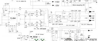
— ULF power supplies:
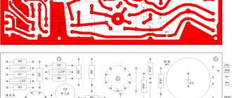
The power supply circuits were pulled from different sources, collected into one circuit and adapted to their components. ([Complete amplifier on microcircuits. Part 4. Improving the power supply » Magazine of practical electronics Datagor, Power supply for TDA7294 and TDA7293) The power supply for 2 ULFs on the TDA7293 also has a low-power stabilized bipolar power supply ±12 V, for connecting auxiliary consumers (preamplifier/low-pass filter of the subwoofer, power supply for the case fan). Otherwise, both power supplies are identical, with capacities of 4x4700 uF for each power arm.
— AC protection devices:
I thought that this was my first experience assembling a ULF, and today one cannot be 100% sure of the quality of the components. I didn’t really want my good old SOLO-3 speakers of the first version (modified by me) to die on my first devices, so I decided that the complex should include speaker protection devices. I took the device diagram from the article by V. Mosyagin (MVV) “Complete amplifier on microcircuits. Part 3. Acoustic system protection device. Connection diagram of amplifier functional blocks" First, I ordered parts and assembled a speaker protection circuit for the left and right channels: But then I decided that the subwoofer also needed its own protection, and since I bought the parts with a small reserve, I had enough for one more board . I redesigned the circuit board for one channel and one relay, although already on FINDER 40.52S (24V), which I had, since I did not take 12 V relays with a reserve. Protection circuit for one channel and 24 V relay:
— Input power filter 220 V:
For the 220V mains voltage input, I made a small board with a varistor, a fuse holder, and an EMI suppression capacitor B32922-C3104-K, 0.1 µF, 305V, X2. The board also included screw terminal blocks for connecting input/output and connecting the power button. My first independent development! ))):
— Input selector and volume control:
Based on positive reviews, a kit based on the PGA2311 chip was chosen (https://www.ti.com/lit/ds/symlink/pga2311.pdf) Unfortunately, there is no longer a page for the product that I bought, but one to one as on this link: PGA2311 3 channel Remote preamplifier kit good for amplifier The kit consists of a main board, a board with a controller and an information display, as well as a small board with an encoder.
On the main board there is a diode bridge with power capacitors, power stabilizers of ±5V for PGA 2311 and 5V for relays, 3 pcs. a relay for switching inputs, the PGA2311 chip itself with wiring, input and output connectors (I soldered the output connector myself). The second board contains a 16x2 display with white symbols on a blue background, a controller, connectors for connecting to the main board and for connecting an encoder. The third board is a piece of PCB with an encoder located on it (with a button) and a 4-wire cable to the board with the controller. By rotating the encoder we change the volume, by pressing we switch the input relays on the main board. The kit also includes a small control panel from which you can adjust the volume and switch source relays.
— Preamplifier / low-pass filter for subwoofer:
I didn’t look for something super complex and of high quality, since later I want to make a low-pass filter/high-pass filter based on the ADAU1701 DSP, so I bought one of the simplest boards on Aliexpress (DC 10-24V Subwoofer Amplifier Preamp Board Subwoofer 22Hz-300Hz Frequency Filter Plate For Diy Kit). The 12V power supply, on the NE5532 op-amp, has two potentiometers: volume control and low-pass filter frequency control, input - 2 channels, output - mono.
— Internal signal source:
My internal source is a Raspberry Pi Model B+, an old model purchased 4 years ago. I took it for study and experimentation, for some time it worked as a media center based on KODI, but its power was not very enough for comfortable work, so the “raspberry” was reoriented to work as an MPD server. Since the linear output of the Raspberry Pi itself is a little creepy, a separate I2C DAC PiFi DAC was purchased on Aliexpress (the same as in this link: PIFI Digi DAC+HIFI DAC Audio Sound Card Module I2S interface for Raspberry pi), which is installed directly on GPIO "raspberries". Without any problems, the system is defined by all audio distributions (Volumio, Runeaudio, Moodeaudio) as “HiFiberry Dac +” The DAC is built on a PCM5122 chip, which is a quite suitable DAC for my ears. Connection to the home network is via Ethernet. How I use it and how the entire user infrastructure is built, I will tell you a little further.
— Multimedia:
Since the Raspberry Pi Model B+ did not work well as a machine for KODI, it was decided not to torture the poor thing and take a simple TVBox on Android. Choosing a ball on TVBox Tanix TX2, a simple and cheap option, and there was a discount at the time of purchase. For subsequent installation in the amplifier, I disassembled the body of the console and pulled out the board. The board is so small that there is an additional weight inside the case) Power supply for the set-top box 5V (5V/2A power supply), connection to the home network via Ethernet (1000 Mbits)
— Power supplies 5V:
To power the Rasberry Pi and Tanix TX2, 5V power supplies were required. I thought about making stabilized power supplies for the 7805, but then I thought that I needed to power them completely separately from the ULF, otherwise the Raspberry Pi would constantly “emergency” shut down when the ULF transformer was turned off, and this is bad for the SD card on which the OS is installed. Several such resets may then not start due to errors. So I came up with an idea to make everything simpler. I took out the boards from the TV box power supply (2A) and the old USB charger (1A), placed them on a thin piece of getinax, installed screw terminals, and soldered the incoming and outgoing wires. This is how it will be installed in the case:
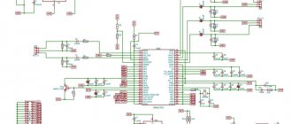
The organization diagram of all the components of my device is presented in the following block diagram. I have displayed all the components and their connections. I did it the same way so that experienced and knowledgeable participants might help me with a small problem.
This is how the components look together, getting ready for installation.
All printed circuit boards were made using LUT. At first I printed on magazine sheets, then purchased thermal transfer paper for LUT. I etch the boards with a solution of hydrogen peroxide and citric acid with salt. I slightly warm the container with the solution in hot water to speed up the reaction. A few photos of my first boards under the spoiler.
First boards, LUT
CHAPTER 2. Amplifier housing.
I built TDA7293 amplifiers and purchased an input selector 4 years ago.
I developed the idea for a case, but basically it was a design made of an aluminum front panel and walls and a top cover made of oak lamellas. It was an almost classic design, easy to make, but during the suspension of the project I was so tired of this design, I always had the feeling that I had seen this somewhere many times and had already had my fill. Therefore, in view of the recent “disease” with the end cut of plywood, the following design was invented:
The case is made of a set of plywood rectangular rings, a one-piece removable top cover, the base of the case is an aluminum sheet, the front panel is darkened plexiglass. My amplifier will be placed on a low hanging cabinet, so its rear part is clearly visible from above. I don’t really like all this heap of cables on the back of devices, long connectors, so in the back of the case I made a small recess in which the input connectors of the connected cables will be hidden. Of course, not everything will be completely hidden, but at least it will be better.
This should be the final look:
To make the structure, a sheet of 10 mm sanded plywood was purchased. Half of this sheet was also spent on the bookshelf speakers from my other review.
Since the workshop is very small, cutting a whole sheet of plywood on a sawing table is not possible. I first divide the sheet into 2-3 parts with a jigsaw. We cut 10 rectangular sheets of plywood, measuring 400 mm x 300 mm.
We set aside the top and bottom sheets, and mark and cut out windows in the eight central sheets with a jigsaw. The wall thickness of each ring is 10 mm.
Glue the 8 resulting rectangular rings together. press on top and bottom with the remaining sheets and tighten with clamps. I use PVA glue Moment Joiner Super.
In the lower part, the window in the sheet is somewhat different; there it is necessary to provide a shelf to deepen the rear panel, as well as a slightly larger thickness of the side walls, which will later be milled to fit the aluminum base.
In the main part of the body, on the sawing table we saw off the back wall for the rear panel, and glue the main part of the body to the lower part.
To fasten the top cover, I chose black M4 bolts with an internal hex head. I made the recesses in the cover for the bolt head in the same way as for the bookshelf speakers from another review, using a 7 mm wood drill, and then a 4.2 mm drill all the way through.
On the side of the body, we glue plywood cubes to the walls, into which we then place mustache nuts (they will be shown in the photo below). Also in the photo you can already see the walls of the rear niche. I cut them out from a large piece that was left over from the sawn-off back of the body. Glued it on PVA.
Then we take an angle grinder in our hands, with a Velcro attachment and a grinding wheel with 80 grit, draw the radii of curvatures of the case on the top cover, and perpendicular to the plane of the top cover we actively work on creating curves at the corners of the case. We also sand the transitions between layers of plywood sheets on the walls of the case, since mistakes were made during gluing (in the photo above you can see that the parts shifted during gluing, I saw it too late, I don’t know how I missed it), but an angle grinder with such a wheel will correct any mistakes , fortunately there is a large margin in the thickness of the case walls))
By the way, beforehand, after gluing the 8 plywood rings of the body, I also used an angle grinder and a wheel with 80 grit to level the inner walls of the body to an even, smooth state. When working with 80 grit, there are both advantages - the speed of work - and disadvantages - scratches. More about the disadvantages a little later.
Amplifier base.
We saw a sheet of aluminum, 4 mm thick and dimensions 380x280. We apply it to the lower part of the body and draw radii. We grind the radii with an angle grinder / Dremel.
We apply the resulting base and trace with a pencil along the bottom of the body.
We take a router with a groove cutter in our hands and make a 4 mm recess for our base. It didn’t turn out very neatly, there’s nowhere to put the base of the router, all the work is almost suspended, the router tends to cut itself, we need tools to expand the base of the router.
We try on the base, mark, drill and countersink holes for attaching the base to the body
It is necessary to cut a window under the front plexiglass front panel. We print out the window from the drawing on a scale of 1:1, glue it onto a piece of cardboard, cut it out with a scalpel, and glue it to the body with double-sided tape.
We cut out the resulting window with a jigsaw.
Now we need to trim the edges of the window. We also do this with an angle grinder and a circle with 180 grit. Of course, you can do this with a router, but for me it takes longer, and you need good skill, here again there is not enough space for the sole of the router, and there are a lot of straight sections, without a stop I can ruin it. Using an angle grinder, with careful soft movements, we draw straight lines and window radii.
We try on the top cover and use a compass to draw a semicircle of recess for the future volume encoder button.
For the front panel, I considered different options. It should be dark so that the LCD display of the output selector can be seen through it, as well as the control panels of the selector and TV set-top box, but at the same time, the insides of the amplifier should not be visible. There was an option to order a piece of glass and tint it, but the mounting holes had to be very close to the edges, and it seemed that it would be expensive, but honestly I didn’t find out the price. Plexiglas is easier with it, but there are a lot of reviews that it doesn’t work well with the tint film, bubbles appear. I tried the option with tinting varnish, but it is very cloudy, the inscriptions on the LCD display are very cloudy. So I chose another option. Two thin sheets of plexiglass, between them a piece of tint film, this “sandwich” and screwed to the body. During the search for thin plexiglass, I was offered to immediately cut out the parts according to my drawing, since they still cut with a laser cutter, and for 200 rubles. I received these two parts already with holes.
But in fact, as it turned out, I received the parts not from plexiglass (acrylic), but from transparent PET 2 mm thick.
I received a piece of film from an auto-tinting company as a gift, with a light transmittance of 30%; this turned out to be optimal for a bright image of the output selector screen and hiding the insides of the amplifier.
Since PET is not particularly afraid of the tint film, I simply glued it to one of the parts and covered the second one on top. I placed a few drops of superglue on top at several points so that the resulting glass would not peel off and dust would not get in there.
When fitting the transparent panel to the body, a small problem was identified. The top cover of the case turned out to be slightly curved, it is not visible to the eye, but there is a hump of 1-1.5 mm upwards. Because of this, the upper extreme points of the panel rested against the housing cover, and in the middle there was a gap between the panel and the housing cover. You cannot buy flat plywood from us. There were two solutions: 1. Sand the front panel under the top cover. But PET is a bit viscous material, I was generally afraid of ruining the finished parts. 2. Make a groove in the top cover. I thought that this option was better, simpler, and as a plus I would fix the panel in the upper part, in a groove, relative to the body. You need to make a groove with a router, the groove is only 4 mm, I have a milling attachment for Dremel, but I had to go find it and get it from the closet, unfasten the flexible shaft, put on the Dremel, and screw on the inconvenient bottom nut. I decided that there was too much work for a simple shallow hidden groove and decided to do it by hand like this:
A thin cutter into a flexible shaft, two steel rulers as a limiter for the cutter’s stroke, and with “muscular” control of the depth of entry of the cutter, we quickly make a groove. Problem solved.
Next we move on to the volume encoder knob. I ordered this pen: 4pcs aluminum plastic knob potentiometer knob 48*19mm potentiometer cap Volume knob switch cap Encoder for amplifier. Diameter - 48 mm.
The diameter of the recess for the handle in the body is 50 mm in diameter and 7 mm in depth. We fasten the housing with the top cover to the table with clamps, place the router and make a recess for the encoder handle and try on the handle.
I took the following power button: [1 pc. Colorful Useful Durable 22mm LED Power Push Button Switch Momentary/Latching Waterproof Metal Self Locking Stainless Buy on AliExpress] Thread diameter is 22mm. The button has a high pressure part; when pressed, the finger does not fall further than the front surface of the button. The hole in the body was made with a step drill.
Next, we take a grinder, grinding wheels with 220 grit, and diligently sand the body. We even grind very diligently, because, as it turned out, it is necessary to remove all the defects from the work of the grinding wheel with 80 grit.
In the photo below you can see the body prepared for oil coating. This is already the second attempt, the first one was unsuccessful, the oil “revealed” all the transverse deep scratches from the coarse grain, they are just not visible on the cut of the plywood. I had to remove the oil and polish it more thoroughly.
After final sanding, coat the body with oil. As the first layer I used BIOFA tinting oil. Dark brown color, apply in a thin layer so as not to lose the texture.
Cover the second layer with BELINKA INTERIER oil. It will give the body a golden hue, as well as a pleasant shine, like oil with wax. Apply this oil in two layers, removing excess.
Next, polish the body with a wool wheel.
We fasten the front panel from the inside of the case with small self-tapping screws.
The hole for the encoder shaft was made with a 7mm drill. On the reverse side, the encoder housing is pressed against the front panel. We install the encoder knob and the power button.
The body is ready!
Legendary amplifiers - historical “anatomy” of trends: reflections on quality, prices and trends
Over the past 60 years, the idea of developers and consumers about what a good UMZCH is has changed many times. However, amplifiers periodically appeared that, thanks to circuitry and design solutions, remained in history as symbols of their era, as standards of quality, as devices that predetermined the development of entire trends.
Analyzing the history of the appearance of the so-called iconic UMZCH over a long period of time, several interesting phenomena can be noted. I will talk about some of them in this article, which, if the user ratings are positive, will become the first in a new series of posts. Today we’ll look at the expensive and not so high-end, what it grew from, what it was, and what it has become.
As the basis for the material, I took reviews of such people as: Peter Breuninger, Dick Olsher, Harry Pearson, etc., as well as a number of publications reflecting the historical significance of devices and the formation of some brands. As it turned out, despite some discrepancies, the authors’ conclusions about the “cult” and historical significance of many famous amplifiers are quite correlated.
Eloquent silence
Already at the stage of analyzing sources, I came across the following: magazines for audiophiles and sympathizers, when it comes to a mass-produced and inexpensive device, do not indicate the price of the device.
At the same time, if at the time the component appeared on the windows it cost several tens of kilobucks, then the price is mentioned almost immediately and attention is focused on it (indicating that this price tag was in such and such a year, and this takes into account dollar inflation et setera). I decided to fill these gaps and found the cost of some devices that were not included in the reviews of seasoned sound experts. One more point, it is connected with the fact that the audio press of the 70s - 90s did not bother themselves, as unnecessary, apparently, with indicating the exact characteristics of the devices they wrote about.
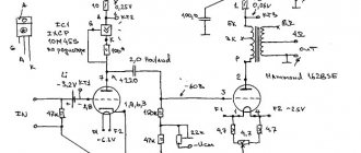
Dynakit (Dynaco ST-70) – DIY kit for the audiophile
This revolutionary product for its time was developed by American sound engineer David Hafler. In 1954, Hafler founded Philadelphia with fellow hi-fi designer Ed Laurent. By 1959, serial production of the ST 70 tube amplifier was launched, which, in a cheaper version (“Dynakit”), was intended for self-assembly.
The audiophile designer's simple and efficient circuit design involved the use of four EL34 tubes, one GZ34/5AR4 and two 7199. The impressive amplifier design was developed by Ed Laurent and Bob Tucker, who used nickel plating on the cabinet surfaces for shielding purposes. This feature also had a positive effect on the aesthetics of the device.
The cost of the kit for creating an amplifier was relatively small and did not exceed $99.95; the assembled amplifier cost a little more, about $130. The most surprising thing about this product was its almost unreal characteristics for that time, at a relatively low price:
RMS - 35W (PMPO: 80W) Response - 10Hz ~ 40kHz at ±0.5dB. Total THD - less than 1%. (20 Hz ~ 20kHz, with 35 W & with 1 dB) IM Distortion - less than 1% with 35 W & less than 0.05% with 1 W. Distortion Noise & hum: 90 dB with RMS. Output impedance - 4, 8 and 16 Ohm. Damping factor: > [email protected] to 1KHz
The cost of the amplifier ($100-$130) was quite decent for 1959, but quite affordable for a representative of the American middle class.
Taking into account inflation, this is about $820 - $1000 today. It should be noted that devices similar in characteristics, and in some respects even inferior to it, cost at that time about $500-$800, i.e. about $4100 - $6500. It was thanks to this difference that this amplifier began to be called McIntosh for the poor, and later Hi-endamp for deadbeat (English: Hi-end amplifier for poor people - author's note). It is clear that today you can find an amplifier with similar characteristics for $820 or less. But it is worth understanding that quite a lot of time has passed for these parameters to become common. However, a tube one is already not enough, “warm” tube Watts are too expensive these days. Moreover, during its release, 350,000 copies of the ST-70 were sold, which is an amount that has no equal for the period of production of this device (1959-1970).
Concert macs of the grateful dead or “warm” tube psychedelia
Today, the McIntosh MC-3500 is the dream of many music lovers and audiophiles nostalgic for the 60s. Audio chroniclers classify it as the so-called True Hi-end. At the same time, the titled UMZCH did not begin its journey in the showrooms of expensive audio stores or in personal studios for listening to music.
The McIntosh MC-3500 was the workhorse of serious concert venues, rehearsal facilities and recording studios. This device was initially positioned as a professional equipment, and only 3-4 years after gaining a reputation as an indestructible and excellent-sounding amplifier for professionals, it was “adopted” by audiophiles.
Like most equipment of its time (manufactured in 1968), the McIntosh MC-3500 was a tube-based one. The characteristics of the device met the requirements of the best concert venues and studios of that time:
RMS - 350W (PMPO: 870 W) Response - 20-20kHz (+0 -0.5dB) Total THD - 0.15%. (8 Ohms less than 20 Hz ~ 20kHz, with 35 W & with 1 dB) IM Distortion - less than 0.9% with 350 W & less than 0.04% with 1 W. Distortion Noise & hum -95dB. Output impedance: 1, 4, 8, 16, 50 and 64 Ohms.
Interestingly, it was these monoblock amplifiers that were used by the legends of psychedelic rock, the Grateful Dead. Perhaps that's why amps that cost $4,000 per pair in the '60s (equivalent to $25,744 in 2022) per pair are now selling at auction for anywhere from $20,000 to $60,000 per monoblock.
Semiconductor standard of the 70s
What can happen when a very good engineer, who opened a very pretentious company (Great American Sound), in a very pretentious time (the 70s of the last century), creates a very pretentious product? That's right, the stereo amplifier is Ampzilla II, a very good amplifier, at a price quite reasonable for the middle class: $629 (which is equivalent to $2,608 today) and unprecedented pretentious advertising.
It is worth noting that this amplifier is worth the money, as its characteristics eloquently speak of, without pretentious advertising:
80 W rms @8 Ohms @ less than 0.08% 20Hz to 20KHz 150 W rms @4 Ohms @ less than 0.02% 20Hz to 20KHz Response: 20-20kHz (+0 -0.5dB) Total THD & IM Distortion 8 Ohms less than 0.08 % Frequency Response and power bandwidth at rated power 0.5Hz to 20KHz — 0.1 dB @8 Ohms Damping factor: > [email protected] Hz to 1KHz Input sensitivity: 1.0 Volts RMS for full power output Input Impedance: 75K Ohms Slew Rate: 40V/ uS Noise: >-100dB
The amplifier was appreciated by its contemporaries; they bought a lot, more than 100,000 units from 1977 to 1982. Paradoxically, tube-orthodox audiophile criticism (in magazines like Stereophile, Pride Audio, etc.) highly appreciated this blatant example of transistor-semiconductor soullessness, with a ridiculous (for Hi End) price tag, noting in particular:
“Many transistor amplifiers, then and now, exhibit impressive performance characteristics, but little more than a sterile, dead sound.
That is, he lacks emotional intensity. This is always different with the Ampzilla II amplifier. Its rhythmic, dynamic presentation captivated all music lovers, while music lovers sought to find more and more detail in the high-frequency spectrum.”
I especially liked the one about emotional tension.
Toroidal monsters of our days
I will deliberately not dwell on several stages of degradation in the evolution of high-end music in the 80s, 90s and noughties (if there is a cycle, we will certainly return to them).
I will skip this long transitional stage so that you can feel the contrast between what was done and valued then and what is done and valued now. Lyrical digression. I’m not sick of retrograde, I don’t pray for vintage, I love and respect progress. I won’t, with the air of a wise old man, talk about “how cool it was” when I wasn’t there, no. But I want readers to note the dominant concepts in which devices that are considered iconic (then “cult”, and now “cult”) are made. So, are you ready? Drumroll…
Name: Opera Only Weight: 1.5 tons Status: cult amplifier of the 2000s, the most expensive sound amplifier on the planet. Creator: industrial designer Andrea Pivett. Design: 6 toroidal transformers, each with a power of 30 kW and 2112 bipolar transistors, which cool 12 powerful coolers. RMS Opera Only (mono): 160,000 W (I was not mistaken, exactly that much) RMS Opera Only (stereo): 80,000 W (per channel) The rest: not published, and may not matter. Other parameters: Practical application:? (I will be glad to see examples in the comments, the creator himself did not reveal the secrets of the monster’s purpose) Price: $ 2,200,000
Bottom line
The significance of a certain product for a generation, to some extent, indirectly speaks of its priorities, its values. Of course, today there are a great many devices, the significance of which will say a lot of good things about us to our descendants. But for some reason it seems to me that there are negligibly few such devices in audio equipment. One gets the feeling that people who appreciated sound in the 70s and 60s were many times smarter than those who today, with a dull, pretentious look and snobbish contempt, declare to others: “What do you understand, this is a sound that costs 100/ 500 thousand bucks." I wish the evaluation criteria were different. But this, of course, is lyrics.
CHAPTER 3. ASSEMBLY OF COMPONENTS INTO THE CASE.
While I was making the case, the configuration of the internal placement of components changed somewhat in my head and a scheme with a two-level arrangement with shelves was chosen.
To attach the boards, it was possible to use special threaded stands, but a large number of them had to be purchased, since it would be necessary to select different lengths. I decided to just go to the hardware store and buy M3 screws of different lengths and different heads (countersunk and flat), as well as washers and nuts. The longest screws are 60 mm. I spent a long time placing the components on the aluminum base, marking the mounting holes, and along the way I thought about how and what would be best to place, taking into account the connected wires. Prepared the mounting of the amplifiers. The radiators of all ULFs were attached to the base using an aluminum corner 40x40x2, using KPT-8 thermal paste
I prepared the mount for the LCD display of the output selector and RaspberryPi with I2C DAC from aluminum corners and plates.
We install vertical posts for future second-level shelves, and also drill (5 mm drill) and countersink ventilation holes for air flow in the base.
We place the ULF power supplies, two ULF left and right channels on the TDA7293, and the transformer mounting bolt.
We place the ULF of the subwoofer, the input selector and volume control board, as well as a “sandwich” of RaspberryPi and I2C DAC.
Laying the ULF power wires
We attach the transformer to the base. To organize the connection of the outputs of the secondary windings, the following block of screw terminal blocks was purchased from a local store and secured to the upper pressure plate of the transformer with a hot glue gun.
We connect the secondary windings to the terminal blocks.
We make a common ground point from the power supplies to the case (from each of the power supplies after the capacitors through 150 Ohm/0.5 W resistors)
To arrange the shelves and place the components on the second level, we cut out and shape with a Dremel the following parts from 4 mm plexiglass. Here is a photo with some drilled holes after trying on the components.
We prepare and lay signal wires from the input selector board to the ULF, wires from the ULF to speaker protection devices, power supply to the subwoofer preamplifier, and estimate the sites.
I came up with the idea of placing the subwoofer preamplifier board vertically, under the platform, but with the potentiometer knobs facing up. I don’t need to constantly twist them; once I set them correctly, I don’t need to touch them any further, so they will be inside, but in an accessible place for adjustment.
We place speaker protection boards, supply power from ULF (0-35 V), as well as outputs to speakers from ULF:
We place the input power board with a fuse, a board with 5V/1A and 5V/2A power supplies, and also place the TV box board on three screws and nuts, but already M2, there were such holes in the board.
We attach the LCD display to the base. It is located close to the front panel, and in order to not see the display board itself, the mounting screws, and also the light from the bright screen diode, I decided to make a frame from thin black plastic. A plastic stationery folder worked perfectly. I cut out a part with a scalpel, also with a hole for the IR control diode, and glued it to the LCD display with double-sided tape.
The rear panel of the case was cut out from the case cover of a non-working DVD player, reinforced on top with an aluminum corner 10x10x1 and screws, and holes were cut for the general power button, as well as a hole for the 220 V cable input.
We outline and cut out the windows for the case fan with a dremel (cutting disc).
We make all the other holes for inputs/outputs (speaker outputs, RCA inputs, 2 x RG45, HDMI)
Paint the entire panel on both sides with black paint (I like BODY Bumper Paint for such purposes)
To connect HDMI to the TV box, I purchased this extension cord, with a socket for the panel: 30cm 50cm 60cm 1m 1.5m Gold Plated HDMI Extension Cable Male to Female With Screw Panel Mount V1.4 HD 1080P For PSP HDTV The plug of this extension cord, however, subsequently had to plan it with a knife, as it rested on the ULF radiator of the subwoofer.
For Ethernet input, panel extension cords were also needed, but all options are either very bulky, and the price is high for such small things. I decided to make my own extension cable with two RJ45 sockets. I removed a quadruple RG45 socket from an old dead router and cut off the two sockets I needed. Then I made fasteners for the panel from a piece of aluminum angle.
I glued the socket to the fastener with epoxy. Then I measured, crimped and soldered sections of twisted pair to the socket terminals. I additionally fixed the soldering points with hot glue.
Let's try out our input jacks and Ethernet cables to the devices:
I bought the case fan offline, 70x70x10. It turned out to be too vigorous, it was necessary to reduce the rotation speed, and significantly, I used a small 6 V zener diode, and then an additional 10 ohm resistor. It rotates much quieter and starts without problems. But perhaps here we will still need to look at the performance during operation; it is possible to increase the voltage if it cannot cope. We attach the fan itself to the back panel with M3 screws, we recess the nuts directly into the mounting holes and fill them with hot glue, so that you can then easily remove the fan from the back panel and not have to look for the nuts inside the case.
The outputs for the speakers and RCA input connectors were purchased as follows (terminals for the speakers and RCA connectors):
OOTDTY 1 Pair RCA Female Socket Connector Chassis Panel Mount Adapter Audio Terminal Plug 2pcs 4mm Gold Plated Amplifier Speaker Binding Posts Oxidation Resistance Brass Terminal w/ Transparent Shell for Banana Plugs
All connectors are isolated from the rear panel.
The 220 V network cable and panel cable entry were taken from the built-in SOLO-3 amplifier. The plug and connector for connecting the network cable after the power button on the rear panel were taken from an old SVEN-620 amplifier. The input network cable was passed through a ferrite barrel.
We mount the RCA input connectors and solder the signal cables.
We mount and connect the output terminals to the speakers:
Photo of the finished rear panel (you also need to buy a fan grille):
To protect against accidental contact with unprotected parts with a voltage of 220 V in the area of the fuse board and 5V power supplies, we make a removable protective screen from 1.5 mm plexiglass:
I took the legs for the case from the following link: AIYIMA 4Pcs Speaker Spikes Stand Feets Audio Active Speakers Repair Parts Accessories DIY For Home Theater Sound System
For fastening I used M3 screws, but they were removed from the inside of the body and glued with epoxy; the legs were secured with M3 nuts.
General view of the finished assembled device:
View of the device in its rightful place:
CHAPTER 4. USER INFRASTRUCTURE.
The entire music collection, as well as movies, are stored on a small home server, in the form of an old Lenovo Thinkpad X61 with Debian Stretch installed.
A server with 3TB of disk space is used as file storage (with access from all devices via NFS), torrent downloader, UPNP server, Nextcloud and Timemachine for Macs.
Both Raspberry Pi and Android TV box are connected to a common home network via Ethernet, with file access via NFS (Kodi on the TV box).
For Raspberry Pi I used different distributions (Volumio, Runeaudio, Moodeaudio), and bare Raspbian with an MPD server installed, but finally settled on the Moodeaudio distribution (www.moodeaudio.org). This distribution seemed to me the most stable, actively developing, and with many working bonuses out of the box.
For remote playback on Raspberry Pi, you can use the following schemes:
— control playback of a music collection from the server via the Moodeaudio web interface:
— control playback of a music collection from the server via the Android application MPDriod
- using Raspberry Pi as a UPNP renderer from the J.River Media Center application (which I use as the main, most adequate application for Macos, for managing the music collection and synchronizing with storage devices for music in the car):
and through the Android application BubbleUPNP. I also sometimes use this application to remotely access my music collection on my home server.
I use MinimServer on Debian as a UPNP server.
I also really like the Cantata application, for accessing the MPD server on Moodeaudio, with downloadable covers and your own playlists. It is available for different platforms and is also being actively developed by the author:
Well, the simplest thing is to use the Raspberry Pi as an Airplay receiver and send a stream from Macos and iOS devices directly. We use this function periodically.
A very short video of using the device:
In the rack
Preamplifier, UMZCH, sources.
That seems to be all.
Postscript:
Naturally, not everything is written, many little things are missing. To write everything completely you need a lot more writing, with emotions, experiences... many technical points are missed. Small things. But the main thing is here.
The easiest thing was to insert the prepared article into the portal editor. It took about 15 minutes at most. And this is exactly what I was afraid of most... The most difficult thing was to write an article. Personally, I don’t really like it from the artistic side. I judge by fact. But that's how it is. I couldn't think of any other way.
If you're reading this, you've read it. Thank you!
Project costs:
COMPONENTS:
| № | Name | Price, rub.) |
| 1 | Transformer (was available) | 3 000 |
| 2 | Textolite 200x300 | 500 |
| 3 | Parts for ULF TDA7293, power supply and input filter | 2 800 |
| 4 | Details for ULF Dorofeev | 600 |
| 5 | BP ULF Dorofeeva | 850 |
| 6 | Parts for AC protection device | 700 |
| 7 | Input selector on PGA2311 | 2 500 |
| 8 | I2C DAC (PiFi DAC) | 1100 |
| 9 | Raspberry Pi | 2500 |
| 10 | TVBox Tanix TX2 | 2600 |
| — | TOTAL COMPONENTS: | 17 150 |
CASE AND COMPONENTS:
| № | Name | Price, rub.) |
| 1 | Plywood 10 mm (sheet) | 850 |
| 2 | Oil | 350 |
| 3 | Potentiometer knob | 340 |
| 4 | Case fan | 170 |
| 5 | Connectors (BANANA) | 320 |
| 6 | HDMI extender | 120 |
| 7 | Case legs | 95 |
| 8 | RCA connectors | 115 |
| 9 | Power button | 210 |
| 10 | Subwoofer low pass filter | 130 |
| 11 | Front Panel Details | 200 |
| 12 | Fasteners | 300 |
| 13 | Wires, lugs, al.profiles (were in stock) | 500 |
| — | TOTAL CASE AND COMPONENTS: | 3600 |
TIME FOR MANUFACTURING AND ASSEMBLY
(days are still evenings, after work, sometimes weekends, but not full days)
| № | Name | Time (days) |
| 1 | Transformer rewinding | 2 |
| 2 | Manufacturing and assembly of ULF TDA7293 and PSU boards | 2 |
| 3 | Manufacturing and assembly of ULF Dorofeev boards | 2 |
| 4 | Manufacturing and assembly of power supply board (Dorofeev ULF) | 1 |
| 5 | Manufacturing and assembly of AC protection devices and input filter (2 pcs.) | 2 |
| 6 | Preliminary connection and testing of components | 3 |
| 7 | Making the case (3 days of which - oil coating) | 11 |
| 8 | Assembling components into the housing | 13 |
| — | TOTAL FOR MANUFACTURING AND ASSEMBLY: | 36 |
| add. | Preparation of the review | 3 |
More time was spent waiting for components and components; if you order cheaper, the delivery takes 2 months; sometimes a small thing slows down the whole process, although there was no need to rush.
PS We spent a long time celebrating the completion of work on the amplifier, but the cat went a little overboard: