We assemble a DIY DAC based on “CS4398”: we solve a hardware flaw in Windows 10
A short story about how an ordinary but inquisitive user like me, at my own expense, had to eliminate the jambs of such giants as Microsoft, Realtek & Adobe.
Special note for "Audiophiles", "Professionals" and so on. I wrote this article with an eye toward the average user, who is neither an audiophile nor an electrical engineer, so further in the text there will be some simplifications and assumptions. I am aware that you know and can do everything, and I ask you to keep your sacred knowledge on choosing the color of wires, the orientation of chips in space and the time of baking disks in the microwave - in this case, to keep to yourself, and not to mislead amateurs in the comments.
What problem is this review addressing? In short, it improves the comfort of using speakers and headphones on a PC at the same time. There is no need to select another device in a running program, no need to switch plugs and turn the master volume control. Ready-made solutions that provide similar comfort and quality cost from $100 and above, but for me everything together came out to less than $30.
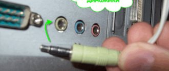
My home PC uses an Asrock Z68 Pro 3 motherboard, with simple, “penny” integrated sound from Realtek. Since this computer is working, I don’t need anything more - to listen to music I prefer to use separate, independent hardware solutions. While Windows 7 dominated the market, everything was fine - the sound played as it should, and no special problems arose, except for JackSense (more on that later). But as soon as Windows 10 became widespread, a new problem appeared - the integrated sound card, or rather its outputs, became visible in the system as two independent devices. Those. The headphone output is a separate device, and the speaker output is separate. Could this be a problem? - you object, and you will be wrong. I will describe a typical usage scenario. I edit the video in Adobe Premiere, the sound comes through the speakers. I connect headphones to the front panel on the PC so as not to disturb others, and the sound still comes through the speakers! Since I now have two sound cards, in order for the sound to go through the headphones, I need to go to the Adobe Premiere settings and specify a different sound card. And so every time, switching between devices. Of course, you can connect headphones to the jack on the speakers, but to do this you need to pull the cord across the entire table, it will get in the way under your hands, and every time you plug and pull the plug out of the jack - why? The notorious JackSense is also not a fountain - it is a feature that cannot be disabled at the hardware level, when the system automatically determines what is currently plugged into which connector on the sound card. The detection works correctly, but it is turned on by software, and until the system boots, a background and buzzing noise is heard from the speakers. Those. Turning on the computer can be heard something like this: “zhzhzhzhffffhhhhhhhhhhhhhhhhhhhhhhhhhhhhhhhhhhhhhhhhhhhhhhhhhhhhhhhhhhhhhhhhhhhhhhhhhhhhhhhhhhhhhhhhhhhhhhhhhhhhhhhhhhhhhhhhhhhhhhhhhhhhhhh (this is when the auto detection turned on) - silence." And things got really bad with the “zhzhzhzh” when, after upgrading the monitor to 4K, I had to buy a discrete video card (RX550) - now “zhzhzhzh” and squeaks began to be heard while scrolling pages in the browser and during other handling of graphics (and I immediately I remembered an unconventional sex called "Launch the i740 on VIA691P via wcpredit" (I have a good power supply, Thermaltake, 800W, that's not the issue). So there was only one way out - change the sound card. I smoked forums and googled on the Internet - Everywhere it's like this bastard - there is no simple solution for reasonable (less than $100) money (there are plenty of ready-made inexpensive DACs with a volume control and a headphone output, but this control also changes the level on the line output), for this reason, I decided that it would be better for me to build a simple DAC for pennies, rather than overpay for all sorts of EAX, DSD, 3D and other features of expensive DACs that I don’t need. As a result, such a completely inexpensive and working design was born, which can be repeated by almost anyone who knows which side to take soldering iron by hand. In general - let's go!
Task:
Build an external DAC that will not receive galvanic interference from the computer and have a separate, adjustable headphone output. Here is a block diagram of how all this will interact.
Components used:
1. Finished DAC board based on CS8416/CS4398.
2. A ready-made headphone amplifier board - depending on the options, can cost from $3 to infinity. I settled on the cheapest option. (assembled by myself)
3. Transformer, with two output windings, for a voltage of 9-12 volts, with a current of at least 200 mA.
4. Housing to accommodate all of the above (preferably metal)
5. Soldering iron, installation wires, solder, rosin, Toslink cable and other consumables.
Before we delve into the assembly process, I'll make a few notes about the components used, talk about alternatives, provide photos with prices and some practical notes.
Note: The prices below are shown as average prices for Aliexpress/ebay. On Taobao they are 3-4 times lower. I got all the details from Taobao.
DAC
You don’t have to take exactly the same one, and on exactly the same chip as mine. There are both more expensive and cheaper models. The main thing here is that the inputs and outputs of the form factor you need are available. It is also worth abandoning very low-cost options, where the output op-amp is soldered into the board - they usually install op-amps of cheap quality, and noise can become a serious problem. So take the option where the output operational amplifier is in the “crib” and can be replaced. I had the regular NE5532, and I installed the original NE5532AN (with normalized noise level). In practice, this gave one thing - if you turn the volume control on the speakers (Genius SP-HF2000X) to maximum, then you hear less noise, but in reality there is no need for such a volume. There is also no point in chasing any extra characteristics. Believe me, as a person who worked as a sound engineer for 10 years, in most cases you won’t hear a real difference, it’s all self-hypnosis.
This is the DAC I use. It works quite well. One of the “disadvantages” is that there is no support for a sampling frequency of 192 kHz, although it is stated. The reason is that other chips, relabeled, were not used (the original marking is visible, i.e. the original chip is also Cirrus Logic, but a different model).
Considering the fact that even at the best age, a person cannot hear anything above 20 kHz, the lack of support for 192 kHz does not seem to me to be a problem at all. For those who like replacing capacitors, only the two on the edge, near the tulip connector, are included in the audio circuit. All others are used only for power supply and do not affect the sound. Price: $10-$15
"DAC-Box". A budget option, I started with it, but quickly abandoned it. The reason is powerful white noise at the output until the PC boots, then everything is fine. I thought that this was incompatibility with my PC, I connected it to a Samsung TV via Toslink - the same thing. But to be fair, this did not happen with the LG TV, so it is quite possible that it will work fine with your PC. But in any case, poor power distribution and a cheap buffer at the output result in noticeable background and noise. Price: $3-5
This DAC is the “Lite” version of the “box”. Same chipset, same problems. Price: $2-4
DACs based on ES9038 and other, more advanced solutions. It's worth installing only if you want to use your PC as a source of high-quality audio. A screen is connected to some modules, an external control panel is connected to others, and so on. In my hearing and opinion, the sound quality does not make any difference with a cheaper analogue, so I consider it overkill to buy one. Counterfeit and relabeled chips are also common here, and given the price, I think it’s easier to “throw away” 10 bucks than “throw away” 30. Price: $30 and up.
Headphone Amplifier
Our Chinese friends offer a wide range of headphone amplifiers, both in the form of ready-made solutions and in the form of assembly kits. I tested several different options, and eventually settled on the version of my own “development”. The reason is lack of space in the selected case.
The so-called “47 amp”. It has a great variety of options, they come with both unipolar and bipolar power supply, different locations of inputs and outputs, and so on. But the principle of operation is the same in all of them, ordinary dual op-amps, such as NE5532, connected in parallel to increase the load capacity. In principle it works, but with default resistors in the feedback circuit, they have too high a gain, which gives a lot of noise at the output. I also noticed quite strong (about 45C) heating of the microcircuits, even without headphones connected. Perhaps there was self-excitation, I did not check. The advantages of this amplifier are that it has mounting points, like the DAC I used, so they can easily be combined into a “shelf” type design. The main disadvantage is the lack of its own power supply (rectifier + stabilizer), although I connected it to the output of the DAC stabilizer, there were no problems with operation - I even wanted to install it in the case, but in this case the transformer did not fit into the case. Price: $5-8
The so-called "British Solo" headphone amplifier. The same NE5532, but the output is amplified by a complementary pair of transistors, which allows you to “drive” high-impedance headphones. It has a 6.35mm headphone jack, its own rectifier and power stabilizer. I liked the sound better than the 47 amp. Price $12-15
Amplifier based on TPA61020A2 chip. The preferred solution of all of the above, since the gain, quiescent currents and other subtleties are set inside the microcircuit right at the factory, and there is less chance for Chinese assemblers to screw something up. Aesthetes can change the capacitors to WIMA, and the resistors to low-noise ones. In reality, this will not give anything, but it will allow you to stroke your ego. The mounting holes are a little closer than those of the DAC under review, but if you drill them out with a 4mm drill, then the bookcase can be assembled, saving space in the case. Price $8-$10
My “self-collection”. The LM4808 chip is used as an amplifier (Used in expensive headphones, for example Audio-Technica ANC7B). We had to “develop” our own version due to lack of space in the case. The cost, taking into account the price of the printed circuit board and audiophile capacitors such as Nichicon FW, Elna Silmic, turned out to be around $10. If anyone wants to repeat it, I can send board files in Sprint Layout/Gerber/DRL format for free, write in the comments where to send it.
Transformer
The requirements for the transformer are as follows. It must have an input voltage suitable for your network (in my case - 230 volts), and have two output windings, or one with a center tap, providing 2x9-12 volts output, with a current preferably at least 200mA. The choice of transformers is huge, but not all are ideal as a power source for a DAC, as they can buzz and have a large scattering field, which will interfere with sound. Based on their external design, transformers can be divided into two types - “regular” and “flooded”. The latter differ from the former in that the entire transformer is filled with a compound, which improves electrical and mechanical strength and eliminates buzz and vibration to almost “0”. In turn, according to their design, transformers can also be divided into two types - with a W-shaped core, and with a toroidal (or, alternatively, with a split strip) core. The first type is cheaper, but the second is preferable, since it has a smaller scattering field (and, accordingly, less interference), and with the same power, the dimensions and weight of toroidal and tape ones are smaller. For clarity, I will provide photographs of each type for ease of identification. I’ll say right away - for a specific application, based on the required power, the type of transformer is not decisive - any will work quite well. The only thing is to remove the transformer at least 10-15cm from the DAC and amplifier boards, if it is type III.
A regular, W-shaped, non-flooded transformer, with lugs for mounting in the housing.
The most inexpensive one available. For use in amplifiers, it is applicable only in cases where it is possible to remove the transformer at least 10 cm from the main board to eliminate interference. Price $3-5
The same transformer, but for soldering into a printed circuit board.
The restrictions on use are the same as above. Price $3-5
“Flooded” W-shaped transformer, with lugs for mounting in the housing. Unlike the usual one, it does not buzz, the distance restrictions are the same as for the usual one. Price $10-15
The same, “filled”, but without ears, for installation in a printed circuit board.
Price $5-10
“Flooded” toroidal transformer. The optimal (and most expensive) option for a homemade DAC. Both in terms of interference, and in terms of noise and occupied space. Price $10-20
Conventional toroidal transformer. Also quite suitable for a homemade DAC, just install it through rubber gaskets so that there is no noise. Price $5-10
A conventional split strip transformer with a round (cross-section) core. There is an opinion that this is especially suitable for powering audiophile equipment. It is unclear to me what this opinion is based on, and the laws of physics are also silent. I have personally observed transformers of exactly this design in completely different, non-audiophile devices, such as bread makers, drying cabinets and centrifuges. Price $15-20
Also an ordinary split-tape transformer, but of the flooded type. It was this model (Myrra 45026) that I used in my design. Price $10-15
Case
Any suitable box can be used as a body. Here the issues of aesthetics and price become decisive - it will work in a box of washing powder, but if you want to get a decent look, you will have to spend money on the case. I recommend a metal case, which is optimal both in terms of reliability and protection from possible external interference. Personally, I used this case, which I bought on Taobao a couple of years ago, and still couldn’t find a use for it. The external dimensions of the box are 127 x 76 x 46mm, and on Taobao it costs about $3. On Ali, of course, it will be more expensive.
Consumables
It’s difficult for me to give advice here, because I don’t know what you have and what you don’t. So read the assembly process further, and see for yourself what you already have from what I used, and what you will need to buy in addition.
Build process
We start by selecting the placement of components in the case - it is logical that the board with the DAC will be in the rear of the case, and the board with the headphone amplifier will be in the front. Initially, I planned to do everything this way, I drilled holes in the case and was already drawing panels to cut them on a CNC router, but I didn’t like the fact that the power transformer wouldn’t fit into the case in this arrangement, I had to build a separate box for it, and the main building will be practically empty. And although I chose a quite nice box for the transformer, my inquisitive mind still haunted me. The main problem was in the amplifier - even if you put it “on a shelf, above the DAC, the volume control must be moved to the front panel, and this means additional wires and interference . There was an idea to lengthen the potentiometer handle, but the transformer got in the way, or it was necessary to lift the board with the amplifier, which ultimately moved the potentiometer to the edge of the case, which in turn would create problems with ergonomics. In general, if the amplifier does not fit into the case, then we make a new amplifier. Having looked at the list of available parts, I chose the LM4808 - This is a specialized headphone amplifier, at one time my Audio-Technica ANC7B headphones burned out, so I immediately bought 3 replacements, and now it’s useful. Of course, the Chinese also offer for sale miniature headphone amplifier modules, say, based on the same TDA1308. But when will it arrive, and what will the quality be like? For this reason, I decided to build it on a chip that I had already listened to and whose sound I liked. I sold the board in literally 10 minutes, ordered it, received it, assembled it, it works! I placed it in the case next to the transformer, I thought that there would be interference, I even asked on the forums how to shield the transformer, but all my fears turned out to be in vain - I did not detect any interference.
After I decided on the relative position of the components, the actual assembly process began. I drilled holes in the bottom of the case, cut M3 threads into them, and screwed in brass spacers like those used when installing motherboards. To fasten the transformer, I used two M2 screws with the corresponding pins, and coated the transformer cover, at the point of direct contact, with thermal paste - this is really not necessary, but I saw this in some measuring system from Motorola - so let me have it too
After installing the components (DAC board and transformer), taking the dimensions, I made a drawing with holes for the aluminum end panels. I cut them out on a CNC machine (Simple CNC machine 2020b, $80 on Taobao). There was a mistake with the hole for the TOSLINK receiver - I didn’t take into account the radius of the cutter, so I had to modify it with a file. Since after all the processing, the aluminum overlays did not look very nice, I used a laser cutter to cut out a false panel overlay from smoky plexiglass for the front panel.
Finally, everything is already assembled and connected to each other, you can turn it on. Please note - to power the headphone amplifier, +12 volts (which are then brought to 5 volts by the stabilizer on the headphone board), I take it from the 12 volt power supply on the DAC board itself, directly from the output of the 78M12 chip. To protect the power cord from chafing, I put thick heat shrink on it and ran it through the ventilation holes in a zigzag pattern so as not to inadvertently tear it out. The ferrite ring on the network cable is more of a fashion statement than a real necessity, the wire was just long and I was too lazy to cut it, so I “shortened it” In the photo it may seem that the headphone jack and its wires directly touch the transformer, but in reality this is not the case, the transformer is at the bottom of the case, and everything else is above, the distance between them is about 4cm. In general, everything works, you can already close the case. On the front, I installed beautiful, “titanium chrome-plated” screws (the term is not mine, that’s what the Chinese wrote in the description). Well, I put the usual, secret ones in the back.
Everything has already been assembled, the moment before the test “launch”
We take +12 volts for the amplifier from the right leg of this microcircuit (marking 78M12). And if your amplifier needs -12 volts, then we take them from the right leg of the nearby microcircuit (marking 79M12).
"Titanium chrome" screws on the front panel.
View from the back.
"Front" view
DAC at the “combat post” (I assembled this table myself, about 15 years ago, and only now, thanks to the DAC, I saw that it turns out that I screwed the shelf above the system unit at an angle
Results
Despite the “sawn” chips, I am satisfied with the sound quality and ease of use. If someone decides to repeat it and needs board drawings and panel drawings, write to me and I’ll send you.
A case where two legs are better than 4
DAC SPECIFICATIONS
Functions and capabilities:
- coaxial and optical inputs,
- works with sampling frequency 32-96 kHz,
- 2-digit sample rate indicator,
- 8x oversampling,
- 24-bit digital filter,
- 24-bit digital-to-analog converters,
- digital de-emphasis (predistortion correction),
- switchable analog filters of the third order (Bessel and Butterworth),
- separate power supply for digital and analog circuits.
Technical specifications:
| rated output voltage | 2.1V (RMS) |
| rated input voltage of coaxial input | 0.5 V (resistance 75 Ω) |
| frequency range (–3 dB) | 0–fs/2 (fs=32/44.1/48 kHz) |
| 0–42 kHz (fs=88.2/96 kHz) | |
| analog filter cutoff frequency | 26 kHz (Butterworth for frequencies fs=32/44.1/48 kHz) |
| 42 kHz (Bessel for frequencies fs=88.2/96 kHz) | |
| output impedance | 100 Ω |
| signal-to-noise ratio | ≥ 114 dBa |
| distortion+noise | 0.0016% (44.1 kHz, 16-bit) |
| 0.001% (48 kHz, 24-bit) | |
| 0.0008% (96 kHz, 24-bit, b=22 kHz) | |
| intermodulation distortion factor (60 Hz/7 kHz, 0 dB) | 0.0035% |
| channel separation (1 kHz) | >115 dB |
| dynamic range | >100 dB |
The measurements were carried out at the following switch positions (see below):
| s1 | s2 | s3 | s4 |
| -1 off | -1 on | -1 on | -1 off |
| -2 off | -2 off | -2 on | -2 off |
| -3 off | -3 off | -3 on | -3 off |
| -4 on | -4 off | -4 off | -4 on |
| -5 on | |||
| -6 off | |||
| -7 off | |||
| -8 off |
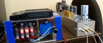
What's high-end without lamps?
I am amused by the hordes of tube-DACs and tube-headphone-amplifiers in the price range from one and a half hundred to hundreds of dollars that have flooded the market lately. Apparently people like the way a light bulb hisses and distorts at 15...24 volts anode. However, an analysis of all the problems of such DACs and pseudo-tube amplifiers for headphones is a topic for a separate article, but not just one.
(photo on the right is an example, I don’t have such a lamp-tac)
Rich topic. I just skimmed the surface here and didn’t touch on the analog part at all. And how interesting it can be to properly lay out the “ground” or organize simple and yet convenient control of the device. And what are attenuators worth - you can choose them with different resistances, build them according to different topologies, and connect them in different parts of the path. Coordinating sources with load is a very, very interesting question, you know!... But for today it’s time for me to wrap up.
Let's start, pay attention...
Where to begin? That's right, it's best to start with a ready-made device, even a simple one, but containing key components. In China, a generally good kit for self-assembly of a DAC was purchased $50 As I already mentioned, the Chinese economic genius is not distinguished by any special technical talents, so everything in that set was at a minimum, exactly according to the datasheets. Except that the creators of the set arranged, as it seemed to them, very high quality food: they stuck “Krenok” with garlands. But the kits came with very suitable R-core transformers.
At this stage, the task was not to somehow specifically control the digital receiver or DAC, so the hard-wired minimalist S/PDIF->I2S->DAC chain suited me quite well.
I didn't consciously try to find a DAC with a USB input. The reason is simple: the computer generates a lot of noise and there is no desire to let all this garbage into the audio device. Of course, there are methods, but I still haven’t come across a single DAC with proper decoupling of the USB input (devices for 1K green and higher, as well as products from Russian “left-handed” audio don’t count).
I consider it necessary to note that despite all my quibbles about the circuit design, etc., the quality of the printed circuit board is simply excellent!
↑ Soldering the first microcircuit
became a living hell for me. I was afraid of overheating it, killing it with static, I soldered the legs a couple of times, but still I soldered it! Of course, you can solder anything to anything if you want, but what is the result? With a shaking hand, I connected the USB cable to the connector... A few seconds of silence and the readiness LED joyfully lights up! All my efforts were rewarded! Well, what do we get out of it? Something is even playing. Well, the soul rushed to heaven, now I’ll torture him! At the same time, I’ll check out the ECC83 + IRF640 hybrid assembled on my knee; I’ll have to try this technology sometime. And I’ll compare its sound with a “clean” lamp.
Taking control of the situation into our own hands
In the documentation for the DAC, in one place it is written that the analog power leg must be bypassed with an electrolyte of 10 μF and ceramics of 0.1 μF. In the diagram, leg 18 is bypassed exactly like this.
A little further in the same document it is said that it is advisable to bypass the input on pin 17 with an electrolyte of 10 μF and ceramics of 0.1 μF. The developer acted in full compliance, a dutiful comrade, just great!
Another place in the documentation says that leg 17 can be connected directly to analog power. What we see in the diagram