Landline phone amplifier on one transistor it will be quite possible boost home phone signal to a sufficient level. Landline phone is now obsolete and a thing of the past, but in some places it is still used. Only the quality of communication via a landline phone leaves much to be desired. This is due to the weak and quiet sound from the telephone handset, which can be amplified by an amplifier. The fleet of landline telephones today is mostly old, sometimes even Soviet telephones with poor audibility. In most cases, these are primitive, purely analog devices, without signal amplification functions. The sound of such telephones is very quiet and sometimes it is difficult to understand the words of the interlocutor. But there is a way out - you can solder a homemade sound amplifier for your phone.
How to boost your home phone signal.
To amplify the signal of a home telephone, it is enough to assemble a simple amplifier using one transistor and power it from the circuits of the same telephone. A regular landline home telephone is supplied with low-current power via a wired communication line, with varying voltage, depending on the operating mode of the telephone (standby, call, conversation). This voltage can be used to power a telephone amplifier. That is, the amplifier does not have to be powered from a separate voltage source. At the same time, this simple home telephone amplifier will in no way disrupt the operating mode of the telephone , since the current consumed is a few milliamps.
Repeater antenna
The quality of the connection amplified by a booster depends on its model as well as on the antennas of the device. They come in two types. Donor or directional is designed for any weather conditions; it picks up the signal outside from the cell tower. The higher they are placed, the more it can be improved.
The internal antenna, also called the service antenna, provides the repeater coverage area. It is mounted on the ceiling or wall of the room.
Note! When choosing an antenna, you should consider what frequency range it supports.
The market offers broadband and single-band antennas. If the former work with all mobile communication standards (within the range of 700-2700 MHz), the latter can catch and amplify only some of them (for example, the 2100 MHz range is allocated for 3G Internet, and GSM communications operate at a frequency of 900 MHz).
According to their action, antennas can be narrowly directed or circular. Directional action is more effective for external signal transmission, while broadcasting it within a certain radius is better for creating coverage.
Phone amplifier circuit.
As you know, a landline telephone is supplied with polar voltage of the following values (depending on the operating mode):
+/- 60 volts – while waiting (with the hook on-hook),
+/- 12 volts – when talking,
+/- 120 volts – when calling (voltage for electric bell).
Naturally, you can’t just connect our telephone amplifier to the telephone line. It will burn out at the moment of the call (when 120 volts appear in the line). The voltage to power the telephone amplifier must be taken from the telephone microphone (pins 8, 9 in the diagram). There is 3 - 5 volts on the microphone of the telephone during a conversation. In other modes of operation of the landline telephone there is no voltage on the microphone. Just what we need. But the second problem is that the phone is supplied with polar voltage. This means that there is a plus on one of the line wires, and a minus on the other. At the same time, for the phone there is absolutely no difference what polarity is supplied to its two wires when connected. The polarity can be changed “painlessly”. But the polarity will change accordingly on the phone microphone . Therefore, the telephone amplifier must be powered from the microphone through a diode bridge in order to prevent a polarity change when the telephone is “wrongly” connected (see diagram below).
After the diode bridge, the supply voltage is supplied to the amplifier stage on transistor VT1, which is loaded onto the telephone capsule. The telephone capsule should have a resistance of 30-300 Ohms. The bias to transistor VT1 is supplied through resistor R1, which must be selected so that the voltage between the collector and emitter of the transistor is equal to half the supply voltage. Resistor R2 – limits the signal level supplied to the cascade. This resistor is actually a volume control . You can, in principle, install a potentiometer that will allow you to more clearly adjust the sound level .
Zener diode D5 is necessary to prevent high voltage surges, for example, in case of problems on the line or poor microphone contact. The nominal value of the voltage stabilized by it should not exceed the maximum voltage between the collector and emitter of transistor VT1. In this circuit, the zener diode can have a voltage of 5-15 volts (zener diode of the D814 series with any letter).
What speed can you get with a repeater?
One of the GSM signal amplifier circuits.
A repeater or booster, which is a more complex device, is designed to establish a stable wireless connection in the area it covers. Its functions include not only receiving a signal from the base station and processing it (amplification), but also distributing the Internet.
An amplifying antenna can increase the speed of an external connection to the maximum established by the tariff. A high-quality repeater can achieve an identical result, with minor speed losses caused by Internet distribution possible.
Reducing the transmission intensity (in addition to dividing it by the number of connected devices) and additional options are determined by the parameters of the device model. A dual-band booster, for example, can double the speed of data exchange on an internal network by receiving and transmitting a signal simultaneously.
Useful information. The external antenna of the repeater must face the cell tower directly.
Telephone amplifier assembly.
The telephone amplifier was originally designed in such a way that its board was located in the handset of the telephone . It is assembled by surface mounting, on a piece of PCB from an old board . Using a mini drill, holes were drilled in the board for the parts in place and mounted on the amplifier board. On the reverse side of the board, the pins of the parts were soldered according to the given amplifier circuit. The handset , just like the telephone board (see diagram), has the same contacts 8, 9, 10. The telephone amplifier located in the handset . The telephone capsule must be disconnected from handset contacts 9, 10 and soldered directly to the amplifier (see diagram).
Headphone device
Mobile phone amplifiers are powered mainly by batteries, so it is important to assemble a device with low energy consumption.
The instructions below meet this requirement. If portability is not so important to the owner, you can build in a connector for power from the mains.
It is not recommended to use impulse parts as they may cause interference and degrade sound quality.
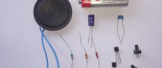
To create a homemade device, it is better to select the following elements:
- copper cable 30-40 cm;
- adapter input;
- microcircuit KA2209;
- plug input;
- 4 capacitors 100 µF.
The assembly circuit can be used from a similar TDA2822 board. You can avoid using a radiator by mounting the device on a wall-mounted unit.
Together with the body, the presented device will measure approximately 10 by 5 cm, which is convenient for carrying in a pocket or backpack along with a smartphone.
Setting up a telephone amplifier.
Setting up a telephone amplifier comes down to selecting the bias resistor R1. It sets the collector-emitter voltage VT1 equal to half the supply voltage. It is also necessary to select resistance R2 for optimal sound volume and the absence of distortion due to over-amplification.
When installing parts on the telephone amplifier board, you need to correctly wire the power source - the diode bridge. So that the plus power is supplied to the transistor collector through the telephone capsule (see diagram).
Me and Diode. © yaidiod.ru.
Problems with the operating system
Problems in the operation of any phone functions are often caused by incorrect firmware of the device. In addition, some firmware simply becomes outdated, as a result of which the phone ceases to efficiently perform its main tasks.
Changing the firmware is not a difficult task; there are many detailed instructions on the Internet to help solve such a problem. Before you start, be sure to save all your contacts and make backup copies of all data in your phone's memory.
Note!
Do-it-yourself charger for a car battery: a step-by-step guide for making the device at home, selecting materials for assembling the structureDIY laboratory power supply | Step-by-step instructions on how and from what elements to build a power supply
DIY antenna for digital TV - photo instructions on how to make simple antennas for digital TV
Often, changing the firmware has a positive effect on the quality of the signal received by the device. If replacing the operating system did not help and the phone continues to have poor reception of signals outside the city, you should assemble a cellular amplifier for your dacha with your own hands.
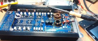
PCB design
Designed amplifier PCB through online software.
This printed circuit board is designed for one channel, so if you are making a stereo amplifier, you need to assemble two identical boards.
PCB Layout Tips
There are four basic principles that you should consider when designing a printed circuit board for an UMZCH:
- Current flowing through a conductor creates a magnetic field that can generate current in a parallel conductor.
- Current flowing in a conducting loop creates a magnetic field. The amount of current is proportional to the area inside the loop.
- Inductance prevents current from flowing. Long, thin traces have greater inductance than short, thick ones.
- A capacitor in series with an inductance creates a resonant circuit.
The traces leading to the non-inverting input and feedback loops should be routed away from the power supply and audio output to prevent high currents from being introduced into low-current traces. If running low current paths near high current paths is unavoidable, use them at 90° angles, never parallel.
If you place the terminals for the high and low current circuits on opposite sides of the circuit board, it will be easier to space them far apart.
Any space between tracks of the same circuit will create a conductive loop that is susceptible to receiving or transmitting magnetic fields. To avoid this, route the positive and negative power paths close together and use grounds at the bottom of the board.
Because the power ground and signal ground must be kept separate, there are two ground planes on the underside of the PCB that are not electrically connected. One ground carries the power ground, and the other ground carries the signal ground. On the top side of the PCB, the power supply, output, and Zobel paths are routed through the ground plane. The input and feedback loop traces pass through the signal ground plane.
To reduce the influence of inductance, it is better to keep all paths as short as possible. This is especially important for the power supply, feedback loop, and Zobel decoupling capacitors. All of them are placed as close as possible to the contacts of the microcircuit to reduce the length.