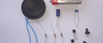
The TDA7294 integrated circuit, according to its characteristics, is a modern single-channel audio amplifier from the famous European company ST Microelectronics. It is used as a basis in class AB ULF Hi-Fi equipment. Has built-in protection functions against short circuit, critical heating and electrical discharges. There is a standby mode when there is no signal at the input and an on/off delay to reduce noise at the output.
For ridiculous money (the price of the device in Russia does not exceed 400 rubles), with the help of a small number of electronic components and a couple of such TDAs, you can assemble a powerful stereo amplifier with good and high-quality sound with your own hands. It is worth considering that currently ready-made modules and soldering kits are sold in radio stores, but their cost is an order of magnitude higher.
Technical specifications
The technical characteristics of the TDA7294 allow you to obtain a maximum power of up to 100 W, with a load circuit resistance of 4 to 8 ohms. This is facilitated by field-effect transistors installed in its preliminary and output stages. The device is famous for its low level of intrinsic distortion and noise, and operates in a wide range of frequencies and supply voltages.
Maximum parameters
Let's consider the maximum values of the maximum permissible operating modes of the TDA7294:
- supply voltage (without signal) VS = ± 50 V;
- peak output current IO = 10 A;
- power dissipation (at Tcase=70 OS) Ptot = 50 W;
- operating temperature range from 0 to 70 °C;
- temperature: crystal Tj up to +150 °C; when stored up to +150 °C.
It is worth considering that the 50 V supplied to the microcircuit is critical and can damage it. Therefore, you should not experiment with such values if you do not want to burn the device. The optimal voltage for a load of 4 ohms is considered to be ±27 V, and for 8 ohms no more than ±35 V.
For use at power levels greater than 10 W, a heatsink must be provided. If you don’t bother with calculations, you can take it from an old computer power supply. In any case, the larger it is, the better. You need to install it through a mica gasket. Additionally, you can install a fan, providing an air outlet.
Separately, it is necessary to say about the choice of voltage source. For the device to produce the stated 100 W for music playback, a power supply with a power of 110 W or more will be sufficient. On many forums it is advised to take a reserve of 250 watts. With such a power supply, this TDA can also cope with a pure sinusoidal signal.
Electrical parameters
The values of the TDA7294 electrical parameters were obtained by the manufacturer under the following measurement modes: supply voltage VS = ± 35 V, load resistance RL = 8 Ohm, air temperature Tamb = 25 °C, operating frequency f = 1 kHz. They are valid if no other values are indicated in the “conditions” column.
Description of circuit elements
Almost all elements can be found in an ATX power supply. Diodes D26-D29 with a breakdown voltage of 400 V, but it is better to take a little higher, at least 600 V. The finished rectifier can be found in the ATX power supply. It is also advisable to use diode bridges for powering the controller at least 600 V. But they can be cheap and popular 1N4007 or similar.
The zener diode that limits the controller supply voltage must withstand 0.7 W of power, so its power rating must be 1 W or more.
Capacitors C18 and C19 can be used with a different capacitance, but not less than 220 µF. Capacitances greater than 470 uF should also not be used due to the excessively increased current when the inverter is connected to the network and the large size - they may simply not fit on the board. Capacitors C18 and C19 are also found in each ATX power supply.
Power transistors Q8 and Q9 are very popular IRF840, available in most electronic stores for 30 rubles. In principle, you can use other 500V MOSFETs, but this will involve changing resistors R12 and R13. When set to 75 ohms, the gate open/close time is about 1 µs. Alternatively, they can be replaced with either 68 - 82 ohms.
Buffers in front of the MOSFET inputs and control transformer I, using BD135 / 136 transistors. Any other transistors with a breakdown voltage above 40 V can be used here, such as BC639 / BC640 or 2SC945 / 2SA1015. The latter can be torn out from ATX power supplies, monitors, etc. A very important element of the inverter is capacitor C10. This should be a polypropylene capacitor adapted to high pulse currents. This capacitor is found in ATX power supplies. Unfortunately, it is sometimes the cause of power supply failure, so you need to check it carefully before soldering it into the circuit.
The diodes D22-D25 that rectify +/- 35V are used UF5408 connected in parallel, but a better solution would be to use BY500/600 single diodes which have a lower drop voltage and higher current rating. If possible, these diodes should be soldered on long wires - this will improve their cooling.
Chokes L3 and L4 are wound on toroidal powder cores from ATX power supplies - they are characterized by a predominant yellow and white color. Cores with a diameter of 23 mm, 15-20 turns on each of them, are sufficient. However, tests have shown that they are not needed - the inverter works without them, reaches its power, but the transistors, diodes and capacitor C10 become hotter due to pulse currents. Reactors L3 and L4 improve inverter efficiency and reduce failure rates.
The D14-D17 +/- 12V rectifiers have a big impact on the efficiency of this line. If this line will power a preamp, additional fans, an additional headphone amplifier, and for example a level meter, diodes should be used at least 1 A. However, if the +/- 12 V line will only power the preamp, which pulls up to 80 mA , you can even use 1N4148 here. Chokes L1 and L2 are practically not needed, but their presence improves the filtering of interference from the power supply. As a last resort, you can use 4.7 Ohm resistors instead.
Voltage limiters R22 and R23 can consist of a series of power resistors connected in series or in parallel to produce a single higher power resistor and corresponding resistance.
Typical connection
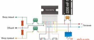
A typical connection diagram for the tda7294 can be taken from the technical description in the datasheet. The VM and VSBY pins are connected to the positive +VS pin. If there is no power to them or less than 1.5 V, the device is turned off. If the voltage increases above 3.5 V, the microcircuit exits the energy-saving state (StandBy) and quiet mode (Mute).
This design can be assembled using the element base shown in the figure. At the same time, for lovers of deep low frequencies, it should be slightly modified. Below are recommendations for choosing capacitors and resistors that will help you get better sound.
In place of C1, it is advisable to install metallized film capacitors of at least 0.33 μF. The larger the capacity, the better the bass will sound. C2 should be 50V and at least 22uF. On the forums it is recommended to set it to 220 uF. C3,C4 (at 50 V) set the on time. Resistors R4 and R5 have approximately the same purpose; it is better to leave their values at 10 and 22 kOhm, respectively.
PIC capacitor C5 only takes place when the power supply exceeds 40 V. On the diagram it is indicated at 22 µF, but it is better to set 220 µF x 50 V. This will also contribute to the appearance of good low frequencies.
C7, C9 are 0.33 µF film capacitors. C6 and C8 can be omitted. Resistor R1 determines the input resistance. R2 and R3 (their ratio R3/R2) set the gain.
Is your car too noisy? Can you hear the rumble of wheels? Then you need high-quality sound insulation for Volkswagen, from professionals in their field.
Operating principle of a switching power supply
The 220 V voltage is rectified by a bridge with diodes D26-D29. The input capacitors C18 and C19 charge to a total voltage of 320V, and since the inverter operates in a half-bridge system, they divide them in half, resulting in 160V per capacitor. This voltage is further balanced by resistors R16 and R17. Thanks to this separation, it is possible to connect transformer T1 to one channel. The potential between the capacitors is then treated as ground, one end of the primary winding is connected to +160 V, the other to -160 V. The switching voltage of the primary winding of transformer T1 is carried out using a variable N-MOSFET transistor Q8 and Q9.
Capacitor C10 and the primary winding of current transformer T3 are located in series with the primary winding. The coupling capacitor is not needed for the operation of the circuit, but it plays a very important role - it protects against unbalanced energy consumption from the input capacitors and, therefore, before charging one of them to more than 200 V. The current transformer T3, also located in series with the primary winding, acts as short circuit protection. The current transformer provides galvanic isolation and allows you to measure the current value, reduced to the accuracy of its transmission. Its task is to inform the controller about the amount of current flowing through the primary winding T1.
In parallel with the primary winding of the main transformer there is a so-called pulse suppression circuit, which is formed by C13 and R18. It suppresses voltage surges generated when switching power transistors. They are not harmful to MOSFETs because their built-in diodes effectively protect against drain overvoltage. However, voltage surges can negatively affect the efficiency of the inverter, so it is important to eliminate them.
The power MOSFETs cannot be driven directly from the controller due to the change in the potential of the upper transistor source. The transistors are controlled using a special transformer T2. This is an ordinary pulse transformer operating in push-pull mode, opening power transistors. The control transformer T2 has at the input a set of voltage control elements on the windings, which, in addition to generating the voltage dictated by the controller, protect against the occurrence of core demagnetizing voltage. An uncontrolled demagnetization voltage would keep the transistor open. The elements directly responsible for eliminating the demagnetization voltage are diodes D7 and D9, as well as transistors Q3 and Q5. During idle time, when both MOSFETs are off, current flows through D7 and Q5 (or D9 and Q3) and maintains the demagnetization voltage around 1.4 V. This voltage is safe and cannot open the power transistor.
Voltage oscillogram at MOSFET inputs:
On the oscillogram you can clearly see the moment when the core stops being demagnetized by diodes D7 and D8 (D6 and D9) and begins to be magnetized in the opposite direction by transistors Q3 and Q4 (Q2 and Q5). During the core demagnetization phase, the voltage at the T2 gate reaches 18 V, and during the magnetization phase it drops to approximately 14 V. Why is one of the IR type drivers not used? First of all, the control transformer is more reliable, more predictable. IR drivers are very capricious and error prone.
An alternating voltage is generated on the secondary winding of the main transformer T1, so it needs to be rectified. The role of the rectifier is played by rectifying fast diodes, generating a symmetrical voltage. The output chokes are located behind the diodes - their presence affects the efficiency of the inverter, suppressing the surges that charge the output capacitors when one of the power transistors is turned on. Next are the output capacitors with preload resistors, which prevent the voltage from rising to too high values.
Bridge connection
The bridge circuit allows you to achieve up to 120 W output. To implement it, you will need two microcircuits and only in cases where the load is 8 or 16 ohms. With less resistance, due to high currents, the TDA may overheat and fail. It represents a design solution from the two standard ones discussed above. In this case, the loudspeaker is connected between the outputs (pin 14) of the microcircuits. The optimal supply voltage for such an assembly is at least 35 V. The input of one of the amplifiers (pin 3) must be connected to ground.
Here it is necessary to have a feedback resistor (22 kOhm) between pins 14 and 2, the first and second microcircuits, respectively. If this is not done, the amplifier will not work.
To turn on the amplifier, at least 5 V must be supplied to pins 10 (Mute) and 9 (StandBuy).
Connecting the volume control
If there is no preamplifier, then the volume control is connected directly to the amplifier. It is important that the input circuits do not have contact with ground or the amplifier housing.
It is recommended to use a variable resistor (potentiometer) with a resistance of 30...50 kOhm as a regulator. The maximum resistance values of the volume control are 5...100 kOhm, but a slight deterioration in sound quality is possible.
It is better to use a variable resistor with an exponential dependence of the resistance on the angle of rotation. Then, when you rotate the control knob, the volume will change in proportion to the angle of rotation. Such Russian-made variable resistors are designated by the letter B, and resistors not produced in Russia are designated by the letter A.
Transistor amplification
To increase the current in the load, the circuit on the tda7294 is strengthened. This can be achieved by adding transistors to the output. There are plenty of examples of such improvements on the Internet. The figure shows one of the options.
The rated power of the amplifier in this design, into a load of 4 ohms, reaches 100 W. The coefficient of nonlinear distortion, when operating at a level of up to 80 W, is significantly less than the standard solution. There is no “ladder” type failure in the cascade at all.
There are also alternative solutions on this TDA on the Internet. One of them is the popular inverting amplifier based on tda7294, based on the circuit from the audiokiller project. For an example of assembling such a module, see the video
Analogs
Which chip is better for the tda7294 or tda7293 audio amplifier? This question comes up often when searching for analogues, since these two TDAs can be called interchangeable (the main condition is that the circuit power supply is no more than 40 V). Their basic parameters are not particularly different.
At the same time, tda7293 has slightly better characteristics in terms of maximum supply voltage and output power. It has improved voltage booster and clip detector functions. The possibility of parallel connection for increased power has been implemented. But, despite these advantages, some radio amateurs consider it more buggy and less reliable to use.
DataSheet for the tda7294 device in pdf format from ST Microelectronics can be downloaded from the link.
↑ Impulsnik
My ordeals with IIP are described in detail in this forum thread //forum.datagor.ru/index.php?showtopic=5627&st=42 Here it is:
Fragment excluded. The full version is available to patrons and full members of the community.
IR2153 is powered from the midpoint of the divider, controls the field workers, and they supply pulses with a frequency of several tens of kilohertz to the primary. The scheme worked immediately (“Well, yes, right away!” someone who read that forum thread might say, but it turned out that everything was correct, my crooked hands are to blame).
Trans was calculated on the advice of the author of the diagram in the Transformer-2 program. Everything was exactly as planned - at idle, and when I connected the amplifiers the voltage dropped. Then a series of experiments followed, with frequency-setting elements C9 and P1 and the secondary of the transformer, as a result, nirvana was achieved at ± 30V output voltage.
Transformer
- 3 glued rings
Fragment excluded. The full version is available to patrons and full members of the community.
As I understand it, the master elements need to select the correct frequency, so that the core does not go into saturation, and so that the field workers do not go into self-heating. By the way, I didn’t have an oscilloscope, but if you have one, it simplifies everything a little. Half of the parts for the SMPS came from the old power supply for the computer, and the radiator came from there.
The real problem was to get a half-bridge with a common anode; I couldn’t find it anywhere, so without further ado I created pornography from 2 Schottky diodes in TO-220 cases. The space on the printed circuit board for stabilizers for the amplifier service circuits was not used.
Before turning on this, or any SMPS, you need to check everything, and check it again, the first turn on is through a 100-150W incandescent lamp, if something goes wrong it will signal, and the field workers may not “go to conquer low-Earth orbit” ©AlexD. The use of SMPS did not affect the sound, but the entire amplifier began to weigh less than one TC180.
