Tube or transistor amplifier? At the end of the last century, this issue was often discussed in various “audiophile” publications. Currently, it is, in fact, no longer relevant, since both options are in demand on the market and firmly occupy their places in various “niches” of audio engineering.
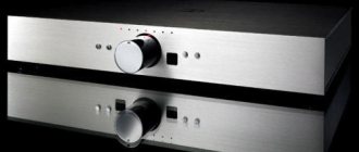
For example, for a home audio system, among modern high-end stereo amplifiers, we offer the “Houston Mini-1998SE” tube amplifier, assembled using 12AX7 and EL84 tubes using a push-pull ultra-linear circuit with a transformer. Despite the limited output power (about 10 W per channel), the sound quality and dynamics of the amplifier with various acoustics, according to experts, is not inferior to high-quality transistor ultrasonics, which develop much greater power.
Interest in Hi-Fi tube amplifiers is currently caused not only by audiophiles’ nostalgia for some special “transparent”, “soft”, “tube” sound, but also by the real advantages of tube ultrasonic frequencies. For practical purposes, the choice is most often made based on the actual capabilities of the amplifier that meets specific requirements.
For example, the construction and operation of a high-quality tube amplifier with a single-ended output stage operating in class “A” mode is in many cases not justified by all indicators, including economic ones. Therefore, many audiophiles and musicians still prefer the classic push-pull tube output stage with a transformer, which, in fact, is the most important element that determines the parameters and quality of the amplifier as a whole.
Make a transformer for a tube amplifier at home
Making a good output transformer at home is quite difficult, but purchasing or ordering one made according to all the rules is not cheap. Recently, there have been proposals to use standard unified transformers such as TAN or TN as output for lamp ultrasonic units. And although in this case you should not count on getting the maximum possible parameters, this option deserves attention due to its accessibility and practicality.
Currently, tube amplifiers used by musicians and released more than 30 years ago still exist. This equipment, as a rule, is “raced” until it is completely worn out. Many years of experience in its operation testify to the reliability of tube amplifiers. Many copies produced, for example, by such companies as BEAG, TESLA, MARC HAL and others, are well preserved. Their repair was most often limited to replacing lamps and electrolytic capacitors.
In more complex cases, it was necessary to replace elements on which the parameters of the amplifiers could depend. Some elements, such as resistors, were destroyed if they malfunctioned. However, it was impossible to determine their denomination from the inscription. It was selected experimentally, as long as the tube amplifier would work, since not all owners and repairmen had circuit diagrams of the equipment.
For these reasons, as well as due to the increased interest in tube circuitry, readers may be interested in the circuits of the most popular pop amplifiers at the end of the last century. These circuits can serve as classic examples of high-quality tube ultrasonic frequencies, which, together with good acoustics, provide the sound quality for which many audiophiles and musicians feel nostalgic.
Power supply
The power supply uses a lamp, a powerful RCA-83 kenotron. The OMRON semiconductor analog timer is used to delay the power supply to the lamp anodes, so that it is possible to warm up using a rectifier. The last 2 RC chains (resistor 3.6 kOhm, capacitor 220 μF and resistor 3.9 kOhm, capacitor 10 μF) are separate for each channel, in the future it is planned to install CCS instead of them, also for each channel. The 10 uF capacitor must be made of polystyrene. Two 50H chokes, 55 Ohm resistance. To power the rectifier filament, the RCA-83 lamp, a voltage of 5 V is used. Heating of the 5687 lamps is provided by a diode bridge assembled on high-speed MUR860 diodes, behind which there are 5 electrolytic capacitors of 10,000 μF each. The LM317 stabilizer, together with a 1.5 Ohm resistor, provides a voltage of 11.5 volts and a current of 830 mA. For more information on power supply design, we recommend looking at the articles on designing power supplies for tube amplifiers.
Simple High Power Tube Amplifier Circuit
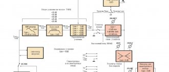
Figure 1 shows the circuit of the Marchal super 100PA amplifier. The tube amplifier provides an output power of 100 W into an 8-ohm load. In this case, the nonlinear distortion coefficient does not exceed 3% (tone controls are set to the middle position). Musicians use a tube amplifier most often as an instrumental amplifier.
The ultrasonic sounder has 4 high-resistance inputs, that is, two parallel: In1 and In2, connected through resistors R1, R2; Vx3 and Vx4, connected through resistors R7 and R8. The mixed signals are amplified in pairs by separate preamplifiers on a dual triode VL1 (ECC83) and through level controls R10 and R13 they are fed to the next amplification stage, the VL2 lamp (ECC83), which also serves as a mixer.
In this case, the frequency response at inputs 1 and 2 (at the output of the cathode follower of the second triode VL2) is linear, and at inputs 3 and 4 it has a rise in the high frequency region, which is achieved by passive frequency correction elements C5, C7, R12. The sound effect obtained as a result of such correction is called “diamond”.
In addition, the pre-amplifier has three tone controls separately for low, mid and high frequencies. The low output impedance provided by the cathode follower makes it possible to reduce the interdependence of passive tone controls, assembled according to a simple circuit with a minimum number of parts (variable resistors R19, R20, R21; constant R18; capacitors C9, C11, C12).
The next phase inverter stage (VL3) is also assembled on a double triode ECC83 and has an adjustable frequency correction (variable resistor R30, capacitor C14) in the negative feedback circuit (NFC), which makes it possible to obtain the so-called “presence effect”, i.e. increase in gain in the mid-frequency region (from approximately 2 to 5 kHz) by 6...8 dB.
It should be taken into account that with the chosen adjustment method, due to the weakening of the negative feedback effect, nonlinear distortions increase, which at maximum amplification at a frequency of 3 kHz can amount to 15%, which is acceptable for instrumental sound and is even liked by some musicians, creating a certain timbre coloring. If the ultrasonic sounder assembled according to this scheme is intended to be used as part of an audio complex for playing music or vocals, it is better not to install these elements at all.
The push-pull output stage is assembled using 4 VL4…VL7 lamps of type EL34 (analogue 6P27S), two connected in parallel in each arm. The selected version of the beam tetrode circuit is the simplest, and therefore, for reliable operation with a minimum coefficient of nonlinear distortion, the selection of lamps with identical parameters is required. In practice this is difficult to achieve. You can limit yourself to choosing lamps from one batch (by year and month of production), if they have not been in use before.
As already noted, the parameters of the amplifier largely depend on the correct calculation and high-quality execution of the output transformer T2. For this amplifier model, we were able to find only a brief description of the transformer: magnetic circuit - Ш32x65 plates: the anode winding consists of 4 sections, each section contains 660 turns, wound with PEL wire with a diameter of 0.27 mm (it is better to use PEV with a diameter of 0.32 mm).
Sections 1 and 3, as well as 2 and 4 are connected in parallel, and their pairs are connected in series. The secondary winding also consists of 4 sections of 160 turns of PEL wire with a diameter of 0.67 mm. All sections are connected in parallel. For those who do not have experience in making output transformers on their own, this data may not be enough, since incorrect placement and connection of any of the windings can cause deterioration of the parameters and even self-excitation of the amplifier.
A more detailed description of the design of the output transformer, recommendations for the selection of materials and its manufacture for the Marchal amplifier. which in its main parameters is close to that described, are given in [4, 5]. Inductor L1 is made on a magnetic core Ш20х40 and has 200 turns of PEL wire with a diameter of 0.41 mm. Data of power transformer T1: magnetic circuit Ш40х55; primary winding for mains voltage 220 V 450 turns of PEL wire with a diameter of 0.62 mm; The secondary winding for powering the anodes of the lamps consists of two halves of 410 turns each, wound with PEL wire with a diameter of 0.41 mm.
Each half at a rated load must provide an alternating voltage of at least 200 V. A special winding designed to obtain a grid bias (38 V) has 78 turns of PEL wire with a diameter of 0.25 mm. The filament winding contains 15 turns of PEL wire with a diameter of 1.8 mm. At the rated network voltage, it must provide a filament voltage of at least 6.3 V.
Setting up the amplifier begins with setting the bias voltage (-38 V) with trimming resistor R47. In order not to cause significant overheating of the output tubes due to the high quiescent current, before starting the adjustment, the resistor slider is set so that the bias voltage is maximum. By adjusting resistor R45, we achieve a minimum background level, while inputs 1-4 are temporarily connected to the common wire.
Despite the worldwide popularity of Marchal tube pop amplifiers, for most of our musicians they have remained a pipe dream. For obvious reasons, variety equipment produced in the CMEA countries has become much more widespread in our country. Sets of variety equipment from the Hungarian company BEAG were very popular at one time.
Usually the kits consisted of three tube amplifiers: two instrumental, one of which was intended specifically for bass guitar, and one voice. Each tube amplifier was equipped with an acoustic system corresponding to its purpose.
The output stages of the amplifiers were built according to identical push-pull circuits on two EL34 beam tetrodes with a transformer and could develop an output power of up to 60 W at an 8 Ohm active load. Figure 2 shows the circuit of the final stage of the instrumentation amplifier “AEX25SG from BEAG.
It includes:
- a pre-tube amplifier (the left half of the double triode VL3), the cathode of which is supplied with a common OOS voltage;
- bass reflex (right half of VL3);
- push-pull output stage using VL4, VL5 (EL34) tubes with a fixed bias (-42 V).
Resistors R26 and R27 are anti-parasitic, eliminate self-excitation of the output stage in the high frequency region, and the divider R29-R30-R36-R37 helps equalize the lamp currents. When using branded amplifiers, these resistors, as well as R34, most often failed. Therefore, it is recommended to install resistors with a power greater than the specified one. An indicator lamp HL2 is connected to part of the secondary winding of transformer T2 through resistor R41.
When the speaker system is turned off, this chain acts as a ballast load. To power the anodes of the amplifier tubes, a rectifier (diodes VD1, VD2), assembled according to a voltage doubling circuit, is used. In this case, the winding of the power transformer T1, which provides the anode voltage (+480 V), must be designed for a current several times greater than that consumed at the rated output power of the amplifier.
Winding T1, designed to produce a bias voltage, should provide an alternating voltage of about 32V, preferably at least 40. Then you can introduce adjustment of the bias voltage by replacing resistor R35 with a tuned one with a resistance of several tens of kilo-ohms. Adjusted resistors RP5 and RP6 are connected to the filament windings, designed to set the minimum background level.
Dual triode tube preamplifier
Figure 3 shows a diagram of the preliminary stages of the AEX250 amplifier. They use two ECC808 dual triodes. The tube amplifier has two identical inputs with separate pre-amplifiers on the VL1 tube and level controls RP1 and RP2, after which the signals are mixed and amplified by a common two-stage amplifier on the VL2 tube.
Passive tone controls for low (RP3) and high (RP4) frequencies are installed between its stages. The circuit does not have any other features. For some capacitors, the operating voltage recommended by the manufacturer is indicated. The “AEX650” voice amplifier model, designed to amplify signals from 4 microphones, differs mainly in the construction of preliminary stages.
At the same time, it has separate tone control for low and high frequencies for each input. The amplifier can be connected to the reverb “AKH200” from BEAG, built on the principle of magnetic sound recording on a ring tape. Data on output transformers suitable for the parameters of the output stage of the AEX250 amplifier can be found in the specified literature.
Case manufacturing
The width of the chassis is determined by the width of the output transformer, since it is the largest component. It is necessary to maintain the dimensions of their mating parts in the workpieces. Before starting assembly, you need to independently drill the necessary holes for connectors and other installation components.
The installation components are inserted into the painted and dried panels. The top panel was not painted, it was sanded and remained the same color as natural aluminum.
Assembly begins by attaching first one side panel to the bottom panel, then the other. The top panel is attached last. The final installation of all components is carried out into the finished tube amplifier housing. The housing for the power supply is made in a similar way. During operation, the signal from its output is supplied by any tube UMZCH with a standard input.
Tube ULF Forum
- SIMPLE TRIODE PREAMPLIFIER
- RIAA CORRECTOR PREAMPLIFIER
- PREAMPLIFIER WITH CONTROLLER AND DAC
- SIMPLE PHONO PREAMPLIFIER