Hello to all Datagorians and guests! It's time to share my next project with you. Even during the work on restoring the Vega EP-110 Stereo player, I had the idea to make a homemade turntable using some components from factory devices. Every day this idea grew stronger, and finally I began to implement it. This article will be devoted to probably the most important component of the turntable - the tonearm.
Contents
- 1 Materials needed for mechanical maintenance
- 2 Disassembling the tonearm 2.1 Features of dismantling the microlift
- 7.1 New tonearm wiring
- 8.1 About the calculation of the anti-roll force
Comrade, here is the hardware for this project
Shell Technics 1200
Good wires for tonearm
Black hexagon screws, different gauges
Digital bars 150-300mm, stainless steel
For drawings of all manufactured elements and parts, see the footer of the article.
When I was repairing my Vega, I had to purchase several similar devices in varying degrees of destruction as donors. But, surprisingly, both had practically intact tonearms. And I thought: “The good stuff shouldn’t go to waste!” In general, from the parts of these two tonearms, I will assemble one, bring it to perfection, and then it will be deeply modernized. But first things first.
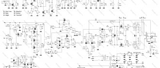
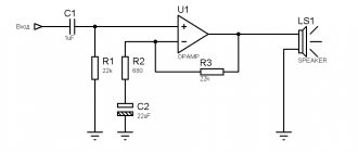
↑ Original diagram
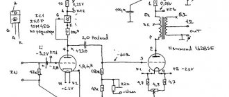
I liked this circuit, so I bought a pair of EF80 lamps for it:
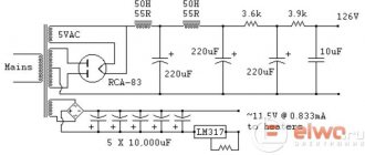
I soldered the circuit quickly, but slowed down on the power supply. I started looking for a security officer to install. I found a trance from some medical equipment. I twisted it, took it apart, unwound the secondary, and calculated how many turns were needed to make an anode trans out of it. I wound it, collected it, measured the voltage approx. 300V AC or 300 x 1.4 = 420V
DC. Just what you need!
↑ Materials needed for mechanical maintenance
1. White spirit.
2. Isopropyl alcohol (isopropanol)
3. XADO Restorative lubricant. This lubricant contains revitalizant, which restores the original geometry of the treated unit.
As a replacement, you can use XADO Repair lubricant. It has the same properties, but is used when parts wear out more significantly.
It is strictly not recommended to use such third-party lubricants. 4. Automotive synthetic oil 5W40. There are no preferences here, take what you have at hand. I had leftover Repsol
5. Clock instrument oil. Synthetic NIICHP-NS-6P is best suited, but you can also use mineral 6. Damper lubricant PMS 250,000. It’s difficult to find with such a viscosity, you can’t just buy it in a store, but you can find it on ad sites
7. Damper lubricant PMS 60,000. This is easier, sold in almost any radio store or on the market
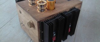
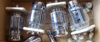
Gallery
Several photos from different stages of amplifier construction.
Rice. thirty.
Power transformer
Rice. 31.
Power and filament transformers assembled
Rice. 32.
Throttle and kenotron sockets assembled
Rice. 33.
Glow circuit routing
Rice. 34.
Amplifier housing
Rice. 35.
Amplifier, top view
Rice. 36.
Amplifier from the inside
Rice. 37.
Amplifier with installed tubes, top view
↑ Disassembling the tonearm
So, first, let's get to know the patient.
Here he is. This is the so-called “high” tonearm. It was placed on Unitra G602 tables. There were also “low” tonearms that were installed on the Unitra G602C (C1). This is the “low” one on my Vega EP-110. Although one of my donors had a “tall” one on the G602 C1 table. In general, the devil will break his leg with these Vegas and Unitras. We subject the patient to complete disassembly down to the last screw. I strongly recommend disassembling the tonearm over a piece of white cloth, because the balls from the vertical axis support are guaranteed to fly apart. For reference: there should be 12 of them, diameter 2.4 mm.
As a result, the victim appears in this form: We send all this stuff (except for the tube and shell) into a jar of white spirit. Soak for several hours to remove all possible grease and dirt. Shake the jar from time to time for better rinsing.
↑ Features of dismantling a microlift
Considering that my tonearm will be subjected to deep modernization, I should have thought in advance about implementing a microlift. There are two possible options here. Oh those Units...
The earlier version (1) is a rotating damper disc.
It has a protruding platform with variable height. When the magnet is triggered, the wire rod turns the disk, and the platform moves, raising the microlift rod. The later version (2) has a simpler design. Here the metal plate acts as a lever. When the magnet is triggered, the plate acts like a rocker arm and itself directly presses on the microlift rod.
Despite the considerable simplicity of the second option, it is absolutely not suitable for my implementation, but the first option should be quite workable. Fortunately, one of my donor tables has just such a microlift. The process of dismantling this damper from its original table will present some difficulty, since it is welded to it. You can, of course, simply remove the damper itself from the bracket, but I also need a mounting bracket. Therefore, you will have to struggle a little with your own table. But with the help of a hand engraver and such and such a mother, everything was solved without any problems.
We disassemble it and put it in a jar of white spirit along with the rest of the tonearm parts. By the way, inside this damper between two metal disks there are 6 balls, exactly the same as in the bearing of the vertical axis of the tonearm. Thus, there are already 18 of them. Don't lose it!
So, after several hours in white spirit, all remnants of lubricants and other contaminants dissolved and disappeared without a trace. We take out the parts and wash them from white spirit in isopropyl alcohol. Particular attention should be paid to the cup on which the balls roll. Take a cotton swab, soak it in alcohol and carefully wipe the path.
↑ Setup and final diagram
The first turn on, the signal was sent and the amplifier began to sing.
This makes me happy!!! Now you need to put the output lamps into mode. I set it to 80 mA (between the anode and the output transformer) by rotating the trimmer to 47 kOhm. I connected an oscilloscope, and it tells me that the lower threshold of the sine wave has been cut off. I decided to get rid of this shortcoming, although I can’t hear it by ear. I started to reduce the bias voltage - it got worse, I returned it to 60V. I started checking all the control points and adjusting them to the desired value. It took a lot of work to get it right. But it’s worth it, the amplifier began to sing even brighter and the step in the oscilloscope readings disappeared, the sine wave became smooth and beautiful.
Many thanks to my fellow Datagorians, they helped me and directed my thoughts in the right direction. Here are the changes I made:
Fragment excluded. The full version is available to patrons and full members of the community.
↑ Rolling bearings
After this, we prepare the working mixture for rolling the bearings. Mix XADO lubricant with automotive synthetic oil 5W40 in a 1:1 ratio. To be honest, I don’t know why this is needed. Perhaps to reduce the viscosity of XADO lubricant, or to make it more penetrating, or to provide a more gentle treatment of parts. This is not my invention, this is how it was described in the article where I got the ideas for repairing the tonearm. So, the prepared mixture has the consistency of sour cream and looks like this:
Place the resulting mixture in a cup, sparingly, and add the balls.
Next, carefully insert the vertical axis, making sure that the balls do not fall out. We clamp the lower end of the axle in the screwdriver chuck and begin to roll in the bearing. Back and forth, at different speeds. You need to apply a little tension, but not too much. You also need to try to center the axis, I used a piece of bamboo skewer as a guide
It is very advisable to do all this over a white cloth, without lifting it high. Make sure the balls don't fly out.
From time to time you need to wipe and inspect the cone. When an even, smooth, shiny stripe becomes visible on it, you need to stop.
Further rolling may result in wear of the cone. We roll the remaining bearings in the same way - each cone to its own bearing. We wrap the cone with 1 layer of electrical tape, clamp it in a screwdriver and roll the bearing. Naturally, we put our lubricant into the bearings.
The result should be something like this. Well, all three cone screws after rolling.
After these procedures, we thoroughly wash all the parts again, successively in white spirit and alcohol. Particular attention should be paid to cleaning small bearings; they are non-separable, and lubricant gets clogged into all the cracks and voids. Therefore, thoroughly rinse the balls in these bearings, rotate them with a toothpick, and blow them out.
↑ Assembling the moving part of the tonearm
Once all the grease has been washed away, you can begin assembling the moving part of the tonearm. Initially, we assemble everything dry without lubricants. To prevent the balls from falling out of the cup during assembly, you can insert something cylindrical of a suitable diameter from below or slightly insert the vertical axis itself and then put the balls into the resulting space
We do not tighten the screws completely, we are just tightening them so that the structure does not fall apart. Then we put a drop of watch oil into each bearing and tighten all the screws. The tightening force of the screws and the play of the tonearm are set according to the ¼ rule: the screws are tightened until the first signs of resistance to rotation appear, after which they are turned in the opposite direction by ¼ turn. The result looks like this
At this point, mechanical maintenance can be considered complete, let’s move on to improvements...
↑ Case and design elements
The time has come for the flight of design ideas. Ideas swarm in the head, and the brain filters and selects real and accessible ones. For the chassis, I took textolite, cut it out, and drilled a hole for mounting in the body.
The case was taken from used medical equipment from Olympus.
I threw out all the internals; they are not suitable for use in lamp structures. Do not rush to dismiss medical equipment; this is a very convenient raw material for structures.
I found a thin sheet of aluminum, cut it out, processed it, sanded it, screwed it on top - under the lamps, it shines beautifully. Nearby, to the left and to the right, metal “fences” are high-quality furniture handles.
I drilled a hole in the volume knob and inserted a small LED onto the glue, and connected it with a thin and very flexible wire, it was also from the bowels of that medical device.
The cover for the output transformers was made of textolite and painted in the color of the body.
I couldn’t figure out what to do on the front panel, because there are a lot of unnecessary holes on it. I decided to insert glass, and behind the glass to place a level indicator taken from Mayak. So that the insides of the amplifier are not visible, I used dark glass. I found a diagram for connecting the indicator:
I gave him a stabilized diet, he works and jumps beautifully to the music. I decided to take the signal from the input in order to see how powerful the signal is entering the amplifier. I turned on the generator at 1000Hz and applied 0.9V to the input, and adjusted it with variable resistors so that the indicator showed all green segments. The indicator setup is complete.
↑ Tonearm height adjustment unit
As you know, the standard design of the Unitra tonearm involves its rigid mounting on the EPU chassis and does not have the ability to adjust the height.
I wanted to have such an opportunity in my player, since it is not always possible to obtain the required VTA angle with a rigid mounting of the tonearm. I couldn’t find ready-made solutions for such functionality, so I had to come up with everything myself from scratch. The idea for the design was suggested to me by a similar device that was developed by JELCO for its tonearms. This gadget is called Jelco Easy VTA and costs more than $200 on eBay. That's it... So, to implement the idea it is necessary to make several additional parts
In the figure: 1 - base, 2 - rod, 3 - support, 4 - sleeve
For a better aesthetic appearance (to my taste), I galvanized the base, as well as some other details, which will be discussed later, in black. Aluminum parts were anodized, and steel parts were chemically oxidized. The structure is assembled as follows: a bronze bushing 4 is attached to support 4 with three M3 screws, rod 2 is similarly attached to base 1 from below. When installing the rod, it should be oriented in a certain way - the flat on the support washer should be positioned in the direction of the hole for the microlift. In order for everything to be in accordance with Feng Shui, the rod should be secured only with black screws?. Like this:
It should look something like this:
Next, the rotating assembly of the tonearm is attached to the base from above: The base assembled in this way is inserted with a rod into the sleeve. There is a milled groove on the rod, and a locking screw in the sleeve. This groove prevents axial rotation of the base relative to the support. To adjust the height, as in the Jelco Easy VTA, I used a micrometer screw
You can buy it, although it's not a top-selling item, or you can get it from an old (or new) micrometer. As a result, the assembled structure looks like this:
After assembly, a small design flaw became clear - there are no problems when lowering the base, but when lifting, the rod in the sleeve gets slightly wedged. This is apparently due to the fact that there are no additional guides in the design. Perhaps in the future I will add them, but for now I will leave everything as it is. In addition, if, when lifting the tonearm, you lightly press the screw in the direction from the central axis, then in general the lifting proceeds normally.
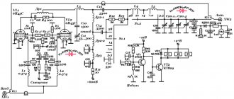
Based on Nobu Shishido. Push-pull amplifier on KT88
https://www.lonica.org/documents/electronics/YT7890IE/2012-shishido-amplifier/ru/body.htm#P00-0100
This push-pull amplifier circuit, the input and driver stages of which are based on this sound genius Nobu Shishido (WAVAC audio lab), was invented by the famous developer of tube audio equipment Mikhail Bron, whose ideas and practical comments helped me implement this project, for which I thank him very much!
The article was corrected in 2016: errors found were corrected.
↑ Microlift
The next unit to work on is the microlift. And if the microlift rod and bushing itself remain unchanged, then the pusher device needs to be slightly modified. First, after washing you need to assemble the damper. When disassembled it looks like this:
Here the figure shows a new part (plate in the top center) that needs to be manufactured. It will serve as a fastening element for the pusher. So, apply PMS 60.000 lubricant to the bottom plate, insert a screw into the central hole and put a plastic disk on it. Place balls into the holes of the disk. We also apply PMS 60,000 to the lower surface of the upper disk and put it on the screw:
We put a lever on the screw on top, and the bent flag on the lever should fit into the slot on the lower disk:
Next, install the plastic sleeve with the outer spring, then the inner spring and tighten the nut on the screw. The tightening force is determined by the smoothness of the damper movement. When tensioning the spring, the upper disk should return smoothly to its original position without jerking. Fix the nut on the screw with a drop of paint. Assembling the microlift rod:
First, we put a lock washer on the thin end of the rod, then we apply PMS 250.000 grease to the rod, insert the rod into the bushing, put a spring and a second lock washer on the thick end. Ready! When installing the bushing in the rotary unit, place it with the thin part of the rod facing up. We put a plastic tip on the rod, insert the bushing into the hole and fix it with a locking screw at such a height that the support area of the tube is horizontal when the rod is raised.
Next, we fix the mounting plate from below on the base of the vertical adjustment unit with three M3 screws, attach the corner bracket to it and the rotary damper itself to it. We adjust the damper so that the damper pressure pad is located exactly under the microlift rod.
Several more problems have emerged here:
1. Minor and easily removable.
In a standard EPU, the damper is fixed relative to the reference plane of the rotating unit of the tonearm at a level of -1.5 mm (thickness of the EPU chassis).
For me this value was -8 mm (thickness of the base of the vertical adjustment unit). Therefore, the damper pressure foot does not reach the rod. In this regard, it will be necessary to make some kind of rod extension, but we will postpone this for later... 2. A more serious unit that requires serious modification.
The fact is that the entire rotary damper was located between the base of the tonearm and the support, and now the degree of lowering of the tonearm is limited to the moment until the damper rests against the lower support. Fortunately, the offending segment can be cut out of the support, and the amount of lowering will increase by the thickness of the base. On the other hand, the maximum lifting height has also now become limited, since the damper mounting plate protrudes beyond the dimensions of the base and, with some lifting, will inevitably rest against the upper panel of the housing from the inside. We can only hope that the available height adjustment range will be sufficient. But we will know this only after installing the tonearm into the body...
Mechanical drawings
Placement of amplifier elements. View from above
Rice. 14.
Placement of amplifier elements. View from above
Dimensions and placement of amplifier elements. Back view
Rice. 15.
Dimensions and placement of amplifier elements. Back view
Top mounting panel
Rice. 16.
Top mounting panel
The bottom panel. Ventilation holes
Rice. 17.
The bottom panel. Ventilation holes
Location of power supply parts. View from above
Rice. 18.
Location of power supply parts. View from above
Location of power supply parts. Side view
Rice. 19.
Location of power supply parts. Side view
Internal mounting panels
Rice. 20.
Internal mounting panels
Mounting panel of the amplifier part
Rice. 21.
Mounting panel of the amplifier part
Partition
Rice. 22.
Partition
Filament transformer mounting panel
Rice. 23.
Filament transformer mounting panel
Rectifier mounting panel
Rice. 24.
Rectifier mounting panel
↑ Assembling the handset
Let's move on. First of all, let's install the shell on the handset. I decided to abandon the standard shell, because it is very heavy, and I am not at all happy with its appearance. As a replacement, we purchased a Technics shell from our Chinese friends.
As you can see, it has contact pins and a connector for a standard bayonet mount on modern tonearms. In our case, such fastening is absolutely useless, so we remove this element without regret.
We grind a new flange to install the shell on the standard tube:
We fix the new flange in the shell hole using two-component epoxy glue.
Before assembling the tube, it makes sense to weigh the shell with flange and the tube. We will need this in the future when determining the compliance of the head and tonearm. In my case, the shell weighs 12.97 g, and the tube - 8.54 g. By the way, the original shell with flange weighs 23.24 g, i.e., more than 10 g heavier than the new one.
No matter how strange it may seem, it is quite difficult to install the shell on the handset correctly. A small device will help us with this. Let's fasten the shell rigidly to a piece of flat plywood
Now let's insert the tube into the flange and measure the distance from the base to the tube near the flange using an improvised gauge (a piece of a cylindrical stick). You can obtain the required diameter by wrapping several layers of electrical tape around a stick.
Obviously, in order for the shell to be fixed to the tube evenly, and the plane of the shell to be parallel to the bending plane of the tonearm, it is necessary that the distance from the base plane to the tube at the other end be equal to the same distance near the flange. Therefore, we install our gauge at the other end of the shell and tighten the locking screw on the flange.
Now the shell is installed perfectly straight on the tube.
↑ New tonearm wiring
The next stage of assembly is to insert the signal wires into the tube.
New wires were purchased for the occasion. We pull the wires through the tube. To dampen the tube, cut small pieces (about 5x10 mm) of the following material:
I can’t say exactly what it’s called, it seems like foamed polyethylene. Used as packaging material. Using a thin stick, we push them loosely (8-10 pieces) evenly along the length into the tube.
Next, solder the ground wire to the shank.
And finally we collect the handset.
↑ Bracket for the horizontal axis of the tonearm
Important!
When assembling the rotary assembly, I was in a hurry and installed the tonearm horizontal axis bracket into the frame.
In this case, it is impossible to install the handset along with the wires into this bracket. You must first put it on the end of the tube, then thread the head wires through it, as well as the ground of the tube from the shank, secure the shank, and only then install the tube assembly into the vertical axis frame. The last step is to properly secure the tube in the horizontal axis bracket. To do this, place the tonearm on a flat surface. I used the same piece of plywood. We place some kind of stand of suitable height under the tube, and attach a flat stick (or something similar) to the shell.
Then we release the locking screw on the horizontal axis bracket and by turning the tube we achieve such a position at which the distance from the supporting plane to the opposite ends of the stick will be equal
Now the tube is installed absolutely straight. Carefully tighten the fixing screw.
Amplifier power supply calculation
Calculation of anode voltage rectifier (Block “A”)
The transformer ME-225 from ISO Tango was chosen as the power transformer.
Rice. 3.
Transformer ME–225
with the following parameters:
Voltage on the primary winding (rms value) U1AC = 230V Nameplate voltages on the secondary windings (rms values) U2AC = 400V–360V–0–100V–360V–400V (360V taps are used to power the anode circuits). The rated current of the anode winding flowing through the 400V I2AC tap = 0.225A.
Nameplate power of the transformer (calculated based on the secondary windings):
P2 = 2 x 5.0V x 3.3A + 6.3V x 3.3A + 10V x 3.3A + 400V x 0.225A = 177VA
Calculation of power consumption of anode and filament circuits
Anode winding
quiescent current of the output lamps: 2 x 65mA = 130mA quiescent current of the driver lamp: 27mA quiescent current of the input stage: 3.8mA bias divider current of the “upper” lamp of the input stage: 2.5mA
Total quiescent current (current flowing through half of the anode winding of the transformer during half a cycle): 130 + 27 + 3.8 + 2.5 = 163.3mA (164mA).
Voltage applied to the kenotron anode during half cycle: U2AC = 360V
Power consumed from the anode winding: 2 x I2AC x U2AC = 2 x 0.164 x 360 = 118VA.
Filament windings
filament current of the GZ34 kenotron: 1.9A (two kenotrons - 3.8A) filament current of the KT88 output lamp: 1.6A (two output lamps - 3.2A) filament current of the EL38 driver lamp: 1.4A filament current of the 6J5G input lamp: 0.3A (taken into account only one “upper” lamp, since the filament of the “lower” lamp is powered from a separate transformer)
Total current of filament windings: 3.8A + 3.2A + 1.4A + 0.3A = 8.7A.
Power consumed from the filament windings: 5.0V x 3.8A + 6.3V x 3.2A + 6.3V x (1.4A + 0.3A) = 19 + 20.6 + 10.7 = 50.3VA.
Total power consumption from the secondary windings of the transformer: P2 = 118VA + 50.3VA = 168.3VA.
Features of connecting a transformer
Filament windings 0–5V 3.3A are paralleled to power the filament of 2 kenotrons.
The 0–5.0V–6.3V 3.3A winding with a 6.3V tap is used to power the filaments of the “upper” lamp of the input stage and the driver lamp. The lower terminal of this winding is connected to a voltage divider, so that half of the anode voltage of the input stage (constant bias) “raises” the filament potential of these lamps in order to eliminate the potential difference between the cathodes and filaments.
The 0–6.3V–10.0V 3.3A winding with a 6.3V tap is used to power the output lamp filaments.
Since a constant bias is not supplied to the “lower” lamp of the input stage, a separate T2 266JB6 filament transformer from Hammond is used to power the filament of the “lower” lamp, as well as the anode voltage supply delay circuit.
The measured active resistance of one half of the anode winding of the transformer = 41.3Ω (400V tap) or 37.2Ω (360V tap), the second half – 43.3Ω (400V tap), or 39Ω (360V tap) can be considered the average resistance value of half of the anode winding of the transformer RTP2 = 42.3Ω (400V tap) or 38.1Ω (360V tap).
Transformation ratio (the ratio of the number of turns of the primary winding to the secondary or the ratio of the voltage on the primary winding to the voltage on the secondary winding) for the anode winding 2 x 360V:
nP = UA / U2AC = 230V / (2 x 360V) = 0.32.
The measured resistance of the primary winding of the transformer RTP1 = 4.4Ω.
Transformer resistance reduced to the secondary winding RTP = RTP2 + RTP1 / nP = 90Ω.
Rectifier operation under static load
In the absence of an input audio signal, for the rectifier the amplifier is a static load with anode current consumed from the power source IP = 164 mA and filament current IF = 8.7 A.
Rice. 4.
Schematic diagram of a rectifier operating on a static load
Voltage drop across the anode winding of the transformer.
The consumed static current IP = 164mA flowing through half of the anode winding of a transformer with an active resistance of 90Ω / 2 will lead to a voltage drop across it equal to 0.164A x 45Ω = 7.4V. Therefore, the voltage UР supplied to the anode of the kenotron will be equal to U2AC – 7.4V = 352V.
Voltage drop across the kenotron.
It is intended to use two parallel kenotrons, so only half the current will flow through one diode, i.e. 164 mA / 2 = 82 mA. For the GZ34 lamp, it is determined from the passport data (see Fig. 5) for a current of 0.082A, the voltage drop across one diode will be 13.5V.
Rice. 5.
Anode characteristics of the GZ34 kenotron (lamp description (by Philips Data Handbook) taken from frank.pocnet)
Thus, the total voltage drop across the active resistance of half of the anode winding of the transformer and the kenotrons is ΔU = 8V + 13.5V = 21.5V.
Direct voltage applied to the anodes of the kenotron at idle speed of the rectifier UP0 = √2 x U2AC = √2 x 360V = 509V. The first filter capacitor must be charged to this voltage when there is no load.
The operating voltage of the first filter capacitor should be approximately 10% greater than the design voltage, i.e. 509 + (509 x 0.1) = 560V (600V).
Since the anode winding and the first filter capacitor are connected in series with respect to the kenotron, then at the moment of the negative half-cycle of the voltage applied to the anode (the kenotron is locked), the kenotron cathode is under the positive voltage of the first filter capacitor Uc. Thus, between the anode and cathode of the kenotron, a double amplitude voltage of the secondary winding appears (Peak Inverse Voltage) Urev = 2 x UP0 = 2 x 509 = 1018V.
The amplitude value of the voltage at the cathode of the kenotron:
UK = √2 x (U2AC – ΔU) = √2 x (360V – 21.5V) = 479V.
Amplitude of voltage ripple on capacitor C1 with a capacity of 47μF:
UC1~ = Iout / (2 x fC x C) = 0.164 / (2 x 50 x 47e–6) = 35V (p–p).
Rectified voltage on the capacitor UC1 = UC – UC1~/2 = 479 – 35/2 = 461V.
In this case, we can consider the rectifier load to be an active resistance RН = Uout / Iout = 461 / 0.164 = 2811Ω. (taking into account the active resistance of the inductor - 40Ω, the load resistance of the rectifier will become equal to 2851Ω).
Calculation of an inductive filter (Block “B”)
To further reduce ripple, an inductive filter was used (see Fig. 6), built on an LC–3–350D inductor from ISO Tango with the following parameters:
L = 3Gn. INOM = 350mA IMAX = 450mA R = 40Ω
Rice. 6.
Inductive filter
Since the inductor has active resistance, the voltage at the filter output (UC2) will be less than the input voltage (UC1) by IP x 40Ω. For a static load of 164mA, this drop will be 6.6V, so the voltage on capacitor C2 at a load current of 164mA will be 454.4V.
Filtering coefficient of the inductive filter CF = 4 x π2 x f2 x L x C2, where
f – ripple frequency of the filtered voltage (for a full-wave rectifier circuit, the ripple frequency is 100 Hz). L – inductance of the inductor, H. C is the capacitance of the capacitor (C2) next to the inductor, F. shows how many times the ripple voltage at the filter output is less than the ripple voltage at the filter input, i.e. CF = UC1~ / UC2~.
Thus, for the selected capacitor C2 = 470μF, CF = 4 x π2 x 1002 x 3 x 470e–6 = 556.6 and the ripple voltage at the filter output UC2~ = UC1~ / CF = 35 / 556.6 = 0.063Vp–p.
The operating voltage of the capacitor at the inductor output due to the insignificant ripple voltage can be selected to be approximately 5% higher than the filter output voltage = 454.4V + 0.05 x 454.4V = 477V (it seems possible to use a capacitor with a standard operating voltage of 550V).
Additional ripple filtering can be achieved with a plug filter consisting of inductor L1 and capacitor C3 connected in parallel to it. If the input and output of the filter choke are shunted with a capacitor, then a parallel resonant circuit (current resonance) will be obtained, which has maximum resistance for the resonant frequency. Such a circuit can be calculated for a resonant frequency of 100 Hz based on the following condition:
Current resonance condition: YC = YL (where Y is conductivity) whence ωC = 1/ωL, whence ω = 1/√(LC). Given that ω = 2πf, we obtain f (100 Hz) = 1/(2π√(LC)). For a 3 H choke inductance, the value of the shunt capacitance will be equal to: Csh = 1/(L x (2 x π xf)2) = 1/(3 x ((2π x 100)2)) = 0.844μF (standard value 0.82μF is selected ).
Minimum value of current flowing through the inductor: IMIN = 2 x √2 x UC2 / (6 x π2 xfx L) = 2 x √2 x 461V / (6 x π2 x 100 x 3) = 73mA. If the amount of current consumed by the load is less than this minimum permissible value, then the smoothing capacitor connected after the inductor will be charged by voltage pulses to the amplitude voltage value at the kenotron cathode under load (i.e. up to 479V).
Calculation of quenching resistors for anode voltages of amplifier stages (Block “B”)
The calculated value of the anode voltage of the output stage of the amplifier UB1 = 452V at a current IB1 = 130mA.
The set value of the anode voltage of the driver stage of the amplifier is UB2 = 320V at a current IB3 = 27mA, so the value of the damping resistor will be equal to (UB1 – UB2) / (27mA + 4mA + 3mA) = 3.9kΩ. The power dissipation across this resistor will be (UB1 – UB2) x (27mA + 4mA + 3mA) = 4.5W
The specified value of the anode voltage of the amplifier input stage is UB3 = 250V at a current IB3 = 4mA, so the value of the quenching resistor will be equal to (UB2 – UB3) / (4mA + 3mA) = 10kΩ. The power dissipation across this resistor will be (UB2 – UB3) x (4mA + 3mA) = 0.5W
The specified current value through the bias voltage divider is I = 3mA, so the total resistance of the divider will be equal to UB3 / 3mA = 83kΩ.
Calculation of the anode voltage supply delay circuit (Block “C”)
The time constant of the delay circuit is τ = C x (R1 x R2 / (R1 + R2)).
at values C = 100μF, R1 = 470kΩ, R2 = 680kΩ we have τ = 28 seconds.
Calculation of a fixed grid bias rectifier (Block “D”)
Range of changes UBIAS = {–35 … –70}V, i.e. The voltage drop across the grid bias resistor will be 30V.
Input alternating voltage of the rectifier U~ = 100V.
Rectified voltage U= = √2 x 100V – U diode = 141V – 1.0V = 140V.
Rectified voltage filter resistor RF = 10kΩ.
The total current of the two dividers is I0 = 6mA, so the drop across the filter resistor UR = 10kΩ x 6mA = 60V.
Thus, the voltage supplied to the two dividers is U0 = √2 x 100V – Udiode – UR = 141 – 1.0 – 60 = 80V, and the total resistance of one divider is R = U0 / (I0 / 2) = 80V / 3mA = 27kΩ.
Current through each divider I1 = I2 = 6mA / 2 = 3mA.
The lower divider resistor in the circuit is selected from the condition of limiting the lower value of the bias voltage –35V: 35V / 3mA = 11.7 kΩ (the standard value of 12 kΩ is used, while the lower value of the bias voltage will be –36V).
The divider potentiometer must provide a voltage change from 36V to 70V, so the voltage drop across it will be 70V – 36V = 34V, which at a current of 3mA will determine its resistance to be 34V / 3mA = 11.3kΩ. (a 10kΩ potentiometer was used, and the grid bias voltage adjustment range was 10kΩ x 3mA = 30V).
The top divider resistor in the diagram is 27kΩ – (12kΩ + 10kΩ) = 5kΩ (the standard value of 5.1kΩ is selected).
The power dissipated in the resistance of the RF filter will be 10kΩ x 6mA2 = 0.36W.
↑ Shank
In the standard version, only the counterweight is installed on the shank. In my version, a new anti-skating and static tonearm balancing unit will also be installed on the shank. Structurally, they are made as a single element
↑ About the calculation of the rolling force compensator
The detailed methodology for calculating the roll force compensator is given in [2].
Here I will give only the main points. It has been experimentally established that the rolling force is equal to: for a spherical (conical) needle Fcc = 0.1 Gpr
;
for elliptical needle
Fce=0.15Gpr
,
where Gpr
is the clamping force of the pickup, g (of course, the force must be expressed in newtons, but to simplify the calculations we will express all acting forces in grams). So for a downforce of 2g
Fcc=0.1×2=0.2
G;
Fce=0.15×2=0.3
g.
To determine the mass of the load, we will use the equation of moments
Fc x Leff = l x Gк
;
Gк = (Fc x Lef)/l
,
where Gк
is the mass of the load, g;
Lef
— distance from the central axis to the stylus (effective length of the tonearm), mm;
l
is the distance from the central axis to the point of application of the compensating force, mm.
Let's take l=30
mm, then for an elliptical needle
Gк=(0.3×220)/30=2.2
g.
We take the mass of the load to be 2.2 g and calculate the distances from the axis to the points of application of the compensating force for different clamping forces.
Taking into account the obtained values, a lever with notches with a pitch of 7.5 mm was made. To use this lever when using a tapered needle head, a 1.47 g weight can be used. In this case, the required compensating force will be provided for the different clamping forces at the same points.
Thus, when installing a new anti-skating unit, it is necessary to ensure that the distance from the vertical axis to the first notch is equal to 15 mm. We install the assembly on the shank, turn it so that the imaginary axes of the lever and the vertical axis of the tonearm lie in the same plane and tighten the locking screw.
The last step is to screw the static balancing lever into the side hole (on the right, if you look at the end of the shank at the back of the tonearm).
The tonearm is almost ready!
Amplifier Parts List
Mechanical elements
Chassis: Hammond Chassis Walnut
| P-HWCHAS1310AL | 2 pcs | |
| Hammond Bottom Panel | P-HHW1310ALPL | 2 pcs |
| Mounting panels (distance between blades - 9.525 mm): | ||
| 47.6 mm 6 petals | P-0602H | 10 pieces |
| 57.2 mm 7 petals | P-0702H | 10 pieces |
| 66.6 mm 8 petals | P-0802H | 10 pieces |
| Clamps for electrolytic capacitors MPSA 35 – 50 mm | MUNDORF-75217 | 6 pcs |
| Bias Voltage Regulator Knobs | P-K310 | 4 things |
| Lamp sockets (CNC) | 14pcs | |
| Rack | M4 30mm FF | 8 pcs |
| Rack | M4 10mm MF | 16 pcs |
| Rack | M3 10mm MF | 8 pcs |
| Rack | M3 10mm FF | 8 pcs |
| Screw | M4 x 6mm | 100 pieces |
| Screw, countersunk head | M4 x 6mm | 100 pieces |
| Screw | M3 x 6mm | 100 pieces |
| Screw, countersunk head | M3 x 20mm | 100 pieces |
| Lock washer | 100 pieces | |
| Lock washer | 100 pieces | |
| Washer | 100 pieces | |
| Washer | 100 pieces | |
| screw | 100 pieces | |
| screw | 100 pieces | |
| Aluminum sheet 2.3 mm | 304 mm x 914 mm | 1 PC |
Electromechanical elements
| Single-core insulated installation wire | 21.5 AWG | 1 reel |
| Single-core insulated installation wire | 16.5 AWG | 1 reel |
| Teflon insulation internal ø 1.5mm external ø 1.8mm | 7.5m | |
| Speaker terminals (long) | 12 pcs | |
| RCA connectors type “D” (inputs) | NF2D-B-0 | 2 pcs |
| Anode voltage terminal (Pomona) | 2142-0 | 2 pcs |
| Anode voltage plug (Pomona) | 3690-0 | 2 pcs |
| Anode Cap (Yamamoto Plate Caps) 6mm | 320-070-91 | 2 pcs |
| Pointer indicator (Yamamoto Precision Panel Meter) 100mA | 320-059-18 | 2 pcs |
| Mains connector (IEC) + fuse | 2 pcs | |
| Power switch (Nikkai) | 2 pcs | |
| Switch for measuring the quiescent current of the final stage (Nikkai) | 2 pcs |
Electronics
| Power Transformer (Tango) | ME–225 | 2 pcs |
| Filament transformer (Hammond) | 266JB6 | 2 pcs |
| Power Choke (Tango) | LC–3–350D | 2 pcs |
| Intermediate transformer (Tango) | NC–14 | 2 pcs |
| Output Transformer (Tango) | XE–60–5 | 2 pcs |
| Kenotron | GZ-34 | 4 things |
| Lamp (GEC) | 6J5GT | 4 things |
| Lamp (Mullard) | EL38 | 2 pcs |
| Lamp (Gold Lion) | KT88 | 4 things |
| Electrolytic capacitor, Mundorf, M-TubeCap | 47μF x 600V | 2 pcs |
| Electrolytic capacitor, Mundorf, M-Lytic HV | 470μF x 550V | 2 pcs |
| Electrolytic capacitor, Mundorf, M-Lytic MLSL HV | 100μF + 100μF x 500V | 2 pcs |
| Quenching resistor, Mills, MRA–12 | 20kΩ 12W | 4 things |
| Quenching resistor, Mills, MRA–12 | 3.9kΩ 12W | 2 pcs |
| Quenching resistor, Mills, MRA–5 | 10kΩ 5W | 2 pcs |
| Electrolytic capacitor, Elna Silmic II | 100uF 16V | 2 pcs |
| Electrolytic capacitor, Elna Silmic II | 470 uF 25 V | 2 pcs |
| Electrolytic capacitor, Elna Silmic II | 100uF 100V | 4 things |
| Anode voltage delay relay (Panasonic) | HC2-H-DC6V-F | 2 pcs |
Comrade, here is the hardware for this project
Shell Technics 1200
Good wires for tonearm
Black hexagon screws, different gauges
Digital bars 150-300mm, stainless steel