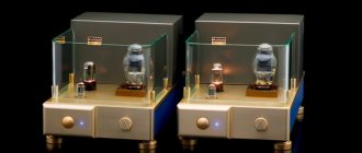
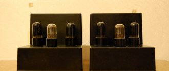
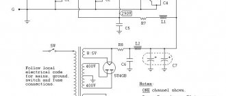
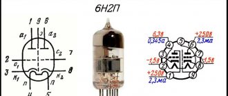
Most of the citizens of this virtual city came here with the desire to make a good amplifier. Some will say that it is better to make a tube amplifier... But this is not the simplest solution. They need rather scarce spare parts - lamps, an output transformer... Others will answer them: “Why lamps? Microcircuit or transistor amplifiers are much more compact and powerful! Well, even if their sound is not so good...” And everyone will be right. This is a matter of taste and capabilities of everyone. It is for the second category of citizens that I decided to write this article.
Two-stage ULF with direct coupling between stages
Examples of ULFs with direct connections and minimal selection of operating modes are the circuits shown in Fig. 11 - 14. They have high gain and good stability.
Rice. 11. Simple two-stage ULF for a microphone (low noise level, high gain).
Rice. 12. Two-stage low-frequency amplifier using KT315 transistors.
Rice. 13. Two-stage low-frequency amplifier using KT315 transistors - option 2.
The microphone amplifier (Fig. 11) is characterized by a low level of self-noise and a high gain [MK 5/83-XIV]. An electrodynamic type microphone was used as the VM1 microphone.
A telephone capsule can also act as a microphone. Stabilization of the operating point (initial bias at the base of the input transistor) of the amplifiers in Fig. 11 - 13 is carried out due to the voltage drop across the emitter resistance of the second amplification stage.
Rice. 14. Two-stage ULF with field-effect transistor.
The amplifier (Fig. 14), which has a high input resistance (about 1 MOhm), is made on a field-effect transistor VT1 (source follower) and a bipolar transistor - VT2 (with a common one).
A cascade low-frequency amplifier using field-effect transistors, which also has a high input impedance, is shown in Fig. 15.
Rice. 15. circuit of a simple two-stage ULF using two field-effect transistors.
Additional functions of standardization circuits
This section discusses some common questions and problems encountered when creating conditioning circuits for sensor signals.
Input protection
Sensor inputs must be protected from electrostatic discharge (ESD), overvoltage, and overcurrent, especially if they are remote from conditioning circuits. These issues are discussed in more detail in the AN929 documentation [14].
Sensor break detection
In this article, schemes were proposed that allow detecting sensor breaks. Some additional information on this subject can be found in AN929 [14].
Filtration
All circuits presented in this article require output filters [3]. Analog filters are used to improve the performance of the ADC. When designed correctly, filters prevent aliasing and allow lower sampling rates, which reduces power consumption and microcontroller load. For most applications, a simple RC filter will be sufficient. For more complex cases, active filters may be required.
FilterLab® software from Microchip Technology Inc. [26] is an innovative tool that simplifies the design of analog active filters based on operational amplifiers. The program is available for free download from the Microchip website. FilterLab allows you to generate a complete filter circuit diagram indicating the ratings and names of the components. It also allows you to export the filter circuit to SPICE format.
If necessary, additional filtering can be performed using DSP methods. For example, even the simplest averaging of results usually gives a good effect.
Analogue to Digital Conversion
The normalized signals from the sensor are digitized using an ADC. For many of the circuits discussed in this manual, it was stated that in order to obtain ratiometric measurements that are not dependent on power supply fluctuations, it is necessary for the ADC to use the same source (VDD) as the ionizer as to power the sensor. In this case, changes in VDD will be compensated by the ADC. However, for many circuits, conventional IONs not tied to VDD will be sufficient.
Adjusting results
Sensor errors can be compensated for using calibration. Calibration can be performed either by hardware, such as potentiometers, or by software algorithms, such as writing calibration data to non-volatile memory.
In addition, it may be necessary to compensate for other environmental factors to make accurate measurements. For example, a capacitive humidity sensor may need to compensate for temperature dependence. This problem is most easily solved using embedded software, but hardware tuning can also be used.
Nonlinear sensors require special correction. This is often done using polynomials or other mathematical functions. To obtain accurate results, you can also use table values. More details on this issue are provided in the AN942 documentation [27].
Literature
main sources
- “The OMEGA® Made in the USA Handbook™,” Vol. 1, OMEGA Engineering, Inc., 2002.
- “The OMEGA® Made in the USA Handbook™,” Vol. 2, OMEGA Engineering, Inc., 2002.
- AN682, “Using Single Supply Operational Amplifiers in Embedded Systems,” Bonnie Baker; Microchip Technology Inc., DS00682, 2000.
- AN866, “Designing Operational Amplifier Oscillator Circuits For Sensor Applications,” Jim Lepkowski; Microchip Technology Inc., DS00866, 2003.
Current sensors
- AN951, “Amplifying High-Impedance Sensors – Photodiode Example,” Kumen Blake and Steven Bible; Microchip Technology Inc., DS00951, 2004.
- AN894, “Motor Control Sensor Feedback Circuits,” Jim Lepkowski; Microchip Technology Inc., DS00894, 2003.
Resistive sensors
- AN863, “A Comparator Based Slope ADC,” Joseph Julicher; Microchip Technology Inc., DS00863, 2003.
- AN251, “Bridge Sensing with the MCP6S2X PGAs,” Bonnie C. Baker; Microchip Technology Inc., DS00251, 2003.
- AN717, “Building a 10-bit Bridge Sensing Circuit using the PIC16C6XX and MCP601 Operational Amplifier,” Bonnie C. Baker; Microchip Technology Inc., DS00717, 1999.
- AN695, “Interfacing Pressure Sensors to Microchip's Analog Peripherals,” Bonnie Baker; Microchip Technology Inc., DS00695, 2000.
- AN512, “Implementing Ohmmeter/Temperature Sensor,” Doug Cox; Microchip Technology Inc., DS00512, 1997.
- AN895 “Oscillator Circuits For RTD Temperature Sensors,” Ezana Haile and Jim Lepkowski; Microchip Technology Inc., DS00895, 2004.
Capacitive sensors
- AN611, “Resistance and Capacitance Meter Using a PIC16C622,” Rodger Richie; Microchip Technology Inc., DS00611, 1997.
Temperature sensors
- AN929, “Temperature Measurement Circuits for Embedded Applications,” Jim Lepkowski; Microchip Technology Inc., DS00929, 2004.
- AN679, “Temperature Sensing Technologies,” Bonnie C. Baker; Microchip Technology Inc., DS00679, 1998.
- AN897; “Thermistor Temperature Sensing with MCP6SX2 PGAs,” Kumen Blake and Steven Bible; Microchip Technology Inc., DS00897, 2004.
- AN685, “Thermistors in Single Supply Temperature Sensing Circuits,” Bonnie C. Baker; Microchip Technology Inc., DS00685, 1999.
- AN687, “Precision Temperature-Sensing With RTD Circuits,” Bonnie C. Baker; Microchip Technology Inc., DS00687, 2003.
- AN684, “Single Supply Temperature Sensing with Thermocouples,” Bonnie C. Baker; Microchip Technology Inc., DS00684, 1998.
- AN844, “Simplified Thermocouple Interfaces and PICmicro® MCUs,” Joseph Julicher; Microchip Technology Inc., DS00844, 2002.
- AN867, “Temperature Sensing With A Programmable Gain Amplifier,” Bonnie C. Baker; Microchip Technology Inc., DS00867, 2003.
Other sensors
- AN865, “Sensing Light with a Programmable Gain Amplifier,” Bonnie C. Baker; Microchip Technology Inc., DS00865, 2003.
- AN692, “Using a Digital Potentiometer to Optimize a Precision Single-Supply Photo Detection Circuit,” Bonnie C. Baker; Microchip Technology Inc., DS00692, 2004.
- TB044, “Sensing Air Flow with the PIC16C781,” Ward Brown; Microchip Technology Inc., DS91044, 2002.
- AN597, “Implementing Ultrasonic Ranging,” Robert Schreiber; Microchip Technology Inc., DS00597, 1997.
Rationing schemes
- FilterLab® 2.0 User's Guide;” Microchip Technology Inc., DS51419, 2003.
- AN942, “Piecewise Linear Interpolation on PIC12/14/16 Series Microcontrollers,” John Day and Steven Bible; Microchip Technology Inc., 2004.
Original article
Translated by Vyacheslav Gavrikov at the request of COMPEL JSC
•••
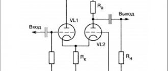
Cascade ULF circuits using bipolar transistors
In Fig. 8 and 9 show circuits of cascode ULFs using bipolar transistors. Such amplifiers have a fairly high gain Ku. Amplifier in Fig. 8 has Ku=5 in the frequency band from 30 Hz to 120 kHz [MK 2/86-15]. ULF according to the diagram in Fig. 9 with a harmonic coefficient of less than 1% has a gain of 100 [RL 3/99-10].
Rice. 8. Cascade ULF on two transistors with gain = 5.
Rice. 9. Cascade ULF on two transistors with gain = 100.
High side current measurement
When measuring high-side current, a current shunt resistor is placed in the open circuit between the power supply and the active load (Figure 3) using a Texas Instruments INA240 as the analog front end (AFE). The common-mode input voltage of this IC can be significantly higher than the supply voltage, making it a good choice for high-side current measurements.
Rice. 3. In the high voltage side current sensing circuit, a current sensing resistor is installed between the power supply and the resistive load.
High-side current measurements have two key advantages over low-side current measurements. First, it is easy to detect a frame fault that occurs within the load because the resulting short circuit current will flow through the current shunt resistor, creating an increased voltage across it. Secondly, this measurement method is not connected to the ground point, so differential voltages on the ground bus created by large flowing currents do not affect the measurement. However, it is still recommended to place the ADC ground reference connection closer to the amplifier ground.
The high-side current measurement method has one major drawback. As noted above, it is necessary for the current amplifier to have high common mode rejection because the small voltage developed across the current shunt is only slightly lower than the load supply voltage. Depending on the system design, the common mode voltage can be quite large. The INA240 current amplifier in Figure 3 has a wide common mode voltage range from -4 to 80 volts.
Track-cascade ULF with direct coupling
In Fig. Figure 7 shows a diagram of another seemingly simple ULF with direct connections between cascades. This kind of connection improves the frequency characteristics of the amplifier in the low-frequency region, and the circuit as a whole is simplified.
Rice. 7. Schematic diagram of a three-stage ULF with direct connection between stages.
At the same time, tuning the amplifier is complicated by the fact that each amplifier resistance has to be selected individually. Approximately the ratio of resistors R2 and R3, R3 and R4, R4 and R BF should be in the range (30...50) to 1. Resistor R1 should be 0.1...2 kOhm. Calculation of the amplifier shown in Fig. 7 can be found in the literature, for example, [R 9/70-60].
Sensor Applications
For each application, a list of the most commonly used sensors is provided. Much useful information on this subject can be found in the OMEGA® Engineering manuals [1, 2].
This article does not list all types of analog sensors; there are many more, for example:
- time/frequency counters [14];
- rangefinders [25];
- measuring current transformers [6].
Information about the behavior of the electrical characteristics of various sensors is necessary for the correct selection of the optimal standardization scheme.
Electrical performance sensors
This group of sensors (Table 1) is necessary for measuring the electrical parameters of the circuit. These sensors are used in a variety of applications, such as monitoring critical performance of power supplies.
Table 1. Sensors of electrical parameters
| Sensor | Output signal |
| Voltages | Voltage |
| Current | Current |
| Charge | Charge |
Magnetic sensors
These sensors (Table 2) are used to determine the magnetic field strength and/or its direction. They are widely used in compasses and electric motor control systems [6].
Table 2. Magnetic sensors
| Sensor | Output signal |
| Hall sensor [6] | Voltage |
| Magnetoresistive | Resistance |
Temperature sensors
Most often, temperature sensors are used for their intended purpose, that is, to measure temperature. Some common types of temperature sensors are listed in Table 3. An overview of temperature sensors can be found in the documentation [14, 15].
Table 3. Temperature sensors
| Sensor | Output signal |
| Thermocouples [19, 20] | Voltage |
| Resistive temperature sensors (RTD) [18] | Resistance |
| Thermistors [16, 17] | Resistance |
| Integral | Voltage |
| IR sensors | Current |
| Thermo generators (Thermo Piles) | Voltage |
Humidity sensors
There are two main types of humidity sensors: capacitive and infrared (Table 4). Humidity sensors very often require additional compensation for temperature errors.
Table 4. Humidity sensors
| Sensor | Output signal |
| Capacitive | Capacity |
| IR sensor | Current |
Force, weight, torque and pressure sensors
This group of sensors is used to measure mechanical forces or deformation. The most common types of sensors are listed in Table 5.
Table 5. Force, weight, torque and pressure sensors
| Sensor | Output signal |
| Strain gauge [8, 9, 10] | Resistance |
| Strain gauges | Resistance |
| Piezoelectric | Voltage or charge |
| Mechanical transducers | Resistance, voltage, etc. |
Motion and vibration sensors
Some common analog motion and vibration sensors are presented in Table 6. Integrated sensors can be used to solve many problems.
Table 6. Motion and vibration sensors
| Sensor | Output signal |
| Differential transformers for measuring linear displacements LVDT [10] | AC voltage |
| Piezoelectric | Voltage or charge |
| Microphones | Voltage |
| Engine sensors [6] | Voltage, resistance, current and so on |
| Ultrasonic distance sensors [25] | Time |
| Integral accelerometers | Voltage |
Flow sensors
There are various ways to measure the flow rate of liquids and gases. A short list of sensors used to solve this problem is presented in Table 7.
Table 7. Flow sensors
| Sensor | Output signal |
| Magnetic flow sensors | AC voltage |
| Coriolis flow meters | Resistance |
| Ultrasound/Doppler sensors | Frequency |
| Hot wire anemometers [24] | Resistance |
| Mechanical transducers, such as turbines | Voltage and stuff |
Liquid level and volume sensors
Table 8 shows examples of liquid level sensors. The volume of liquid in a tank of a known cross-section can be determined by its level.
Table 8. Liquid level and volume sensors
| Sensor | Output signal |
| Ultrasonic | Time |
| Mechanical transducers | Resistance, Voltage |
| Capacitive | Capacity |
| Mechanical switches | On off |
| Thermal | Resistance |
Light and IR sensors
Light and IR radiation sensors (Table 9) are used to detect objects, including in poor visibility conditions.
Table 9. Light and IR sensors
| Sensor | Output signal |
| Photodiode [22, 23] | Current |
Electrochemical sensors
Table 10 provides a short list of electrochemical sensors that are used to measure various chemical properties.
Table 10. Electrochemical sensors
| Sensor | Output signal |
| pH electrode | Voltage (high internal resistance) |
| Conductivity | Resistance |
| CO sensor | Voltage or charge |
| Turbidity sensor (photodiode) | Current |
| Colorimeter (photodiode) | Current |

